ignition SKODA FABIA 2014 2.G / 5J Workshop Manual
[x] Cancel search | Manufacturer: SKODA, Model Year: 2014, Model line: FABIA, Model: SKODA FABIA 2014 2.G / 5JPages: 197, PDF Size: 13.56 MB
Page 167 of 197
WARNING■A discharged vehicle battery may already freeze at temperatures just be-
low 0 °C. If the battery is frozen, do not jump start with the battery of an-
other vehicle – there is a risk of explosion.■
Pay attention to the warning instructions relating to working in the en-
gine compartment » page 138.
■
The non-insulated parts of the terminal clamps must never touch each
other – there is a risk of short circuit.
■
The jump-start cable connected to the positive terminal of the battery
must not come into contact with electrically conducting parts of the vehicle
– there is a risk of short circuit.
■
Do not clamp the jump-start cable to the negative terminal of the dis-
charged battery. There is the risk of detonating gas seeping out the battery being ignited by the strong spark which results from the engine being star-
ted.
■
Route the jump-start cables so that they cannot be caught by any rotat-
ing parts in the engine compartment.
■
Do not bend over the battery – there is a risk of caustic burns.
■
The vent screws of the battery cells must be tightened firmly.
■
Keep any sources of ignition (naked flame, smouldering cigarettes, etc.)
away from the battery – risk of explosion!
■
Never jump-start vehicle batteries with an electrolyte level that is too low
– risk of explosion and caustic burns.
CAUTION
■ There must not be any contact between the two vehicles otherwise current
may flow as soon as the negative terminals are connected.■
The discharged battery must be properly connected to the system of the ve-
hicle.
■
We recommend you buy jump-start cables from a car battery specialist.
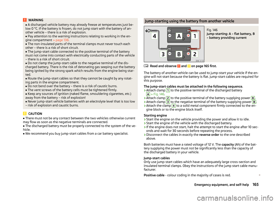
Jump-starting using the battery from another vehicleFig. 146
Jump-starting: A – flat battery, B
– battery providing current
Read and observe and on page 165 first.
The battery of another vehicle can be used to jump-start your vehicle if the en-
gine will not start because the battery is flat. Jump-start cables are required for
this purpose.
The jump-start cables must be attached in the following sequence.
›
Attach clamp
1
to the positive terminal of the discharged battery
A
» Fig. 146 .
›
Attach clamp
2
to the positive terminal of the battery supplying power
B
.
›
Attach clamp
3
to the negative terminal of the battery supplying power
B
.
›
Attach the clamp
4
to a solid metal component firmly connected to the en-
gine block or to the engine block itself.
Starting engine
›
Start the engine on the vehicle providing the power and allow it to idle.
›
Start the engine of the vehicle with the discharged battery.
›
If the engine does not start, halt the attempt to start the engine after 10 sec-
onds and wait for 30 seconds before repeating the process.
›
Disconnect the cables in exactly the reverse order to the one described
above.
Both batteries must have a rated voltage of 12 V. The capacity (Ah) of the bat-
tery supplying the power must not be significantly less than the capacity of
the discharged battery in your vehicle.
Jump-start cables
Only use jump-start cables which have an adequately large cross-section and
insulated terminal clamps. Obey the instructions of the jump start cable manu-
facturer.
Positive cable - colour coding in the majority of cases is red.
165Emergency equipment, and self-help
Page 168 of 197
Negative cable - colour coding in the majority of cases is black.
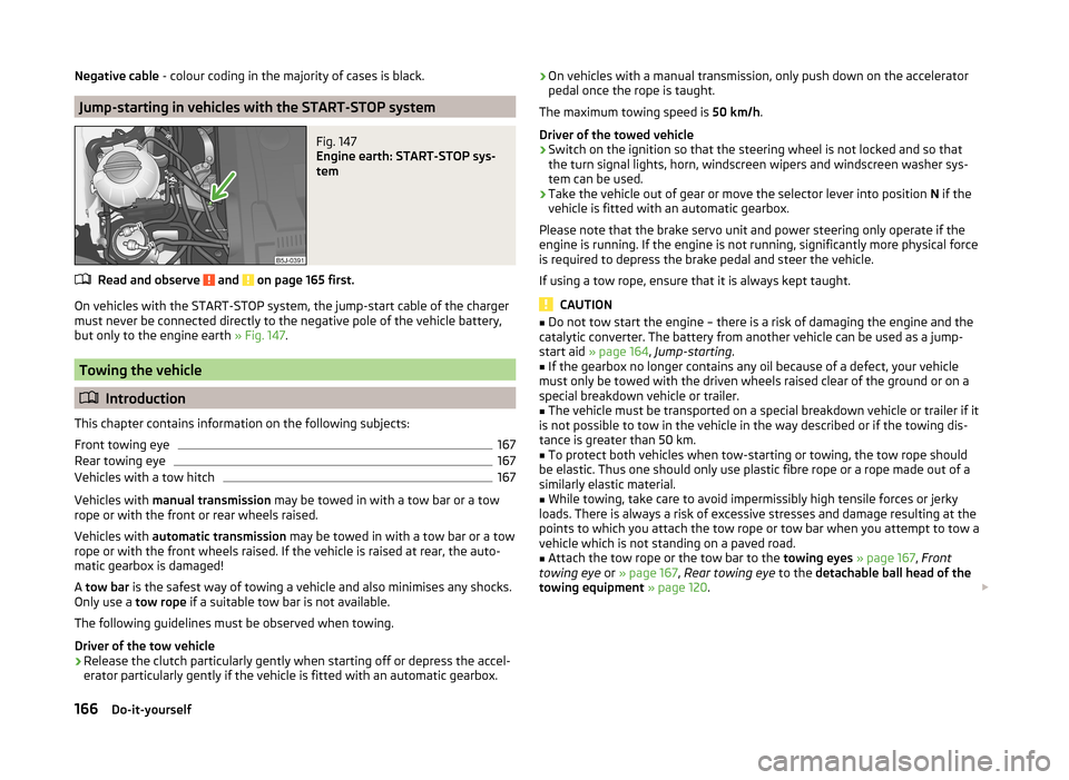
Jump-starting in vehicles with the START-STOP system
Fig. 147
Engine earth: START-STOP sys-
tem
Read and observe and on page 165 first.
On vehicles with the START-STOP system, the jump-start cable of the charger
must never be connected directly to the negative pole of the vehicle battery,
but only to the engine earth » Fig. 147.
Towing the vehicle
Introduction
This chapter contains information on the following subjects:
Front towing eye
167
Rear towing eye
167
Vehicles with a tow hitch
167
Vehicles with manual transmission may be towed in with a tow bar or a tow
rope or with the front or rear wheels raised.
Vehicles with automatic transmission may be towed in with a tow bar or a tow
rope or with the front wheels raised. If the vehicle is raised at rear, the auto-
matic gearbox is damaged!
A tow bar is the safest way of towing a vehicle and also minimises any shocks.
Only use a tow rope if a suitable tow bar is not available.
The following guidelines must be observed when towing.
Driver of the tow vehicle
›
Release the clutch particularly gently when starting off or depress the accel-
erator particularly gently if the vehicle is fitted with an automatic gearbox.
› On vehicles with a manual transmission, only push down on the accelerator
pedal once the rope is taught.
The maximum towing speed is 50 km/h.
Driver of the towed vehicle›
Switch on the ignition so that the steering wheel is not locked and so that
the turn signal lights, horn, windscreen wipers and windscreen washer sys-
tem can be used.
›
Take the vehicle out of gear or move the selector lever into position N if the
vehicle is fitted with an automatic gearbox.
Please note that the brake servo unit and power steering only operate if the
engine is running. If the engine is not running, significantly more physical force
is required to depress the brake pedal and steer the vehicle.
If using a tow rope, ensure that it is always kept taught.
CAUTION
■ Do not tow start the engine – there is a risk of damaging the engine and the
catalytic converter. The battery from another vehicle can be used as a jump-
start aid » page 164 , Jump-starting .■
If the gearbox no longer contains any oil because of a defect, your vehicle
must only be towed with the driven wheels raised clear of the ground or on a
special breakdown vehicle or trailer.
■
The vehicle must be transported on a special breakdown vehicle or trailer if it
is not possible to tow in the vehicle in the way described or if the towing dis-
tance is greater than 50 km.
■
To protect both vehicles when tow-starting or towing, the tow rope should
be elastic. Thus one should only use plastic fibre rope or a rope made out of a
similarly elastic material.
■
While towing, take care to avoid impermissibly high tensile forces or jerky
loads. There is always a risk of excessive stresses and damage resulting at the
points to which you attach the tow rope or tow bar when you attempt to tow a
vehicle which is not standing on a paved road.
■
Attach the tow rope or the tow bar to the towing eyes » page 167 , Front
towing eye or » page 167 , Rear towing eye to the detachable ball head of the
towing equipment » page 120 .
166Do-it-yourself
Page 170 of 197
Fuses and light bulbs
Fuses
Introduction
This chapter contains information on the following subjects:
Fuses in the dash panel
168
Fuses in the engine compartment
170
Individual electrical circuits are protected by fuses.
› Before replacing a fuse, switch off the ignition and the appropriate consumer
› Find out which fuse belongs to the component that is not operat-
ing » page 168 , Fuses in the dash panel or » page 170 , Fuses in the engine
compartment .
› Take the plastic clip out of its fixture in the cover of the fuse box, place it on
the relevant fuse and pull it out.
Fuse colourMaximum amperagelight brown5dark brown7.5red10blue15yellow20white25green30WARNINGAlways read and observe the warnings before completing any work in the
engine compartment » page 138.
CAUTION
■
“Never repair” fuses or replace them with a fuse of a higher amperage –
there is a risk of fire. This may also cause damage at another part of the elec-
trical system.■
Have the electrical system checked as quickly as possible by a specialist ga-
rage if a newly inserted fuse blows again after a short time.
■
A blown fuses is recognisable by the molten metal strip. Replace the faulty
fuse with a new one of the same amperage.
Note■
We recommend that you always carry replacement fuses in the vehicle. A box
of replacement fuses can be purchased from ŠKODA Original Accessories.■
One fuse may cover several consumers.
■
A single consumer may use several fuses.
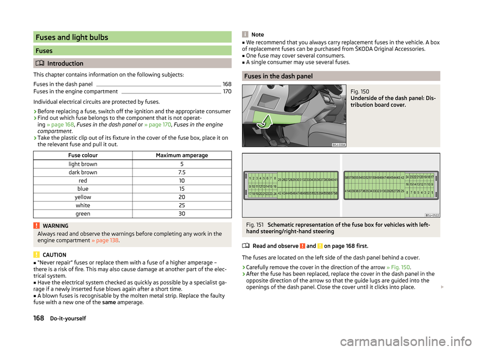
Fuses in the dash panel
Fig. 150
Underside of the dash panel: Dis-
tribution board cover.
Fig. 151
Schematic representation of the fuse box for vehicles with left-
hand steering/right-hand steering
Read and observe
and on page 168 first.
The fuses are located on the left side of the dash panel behind a cover.
› Carefully remove the cover in the direction of the arrow
» Fig. 150.
› After the fuse has been replaced, replace the cover in the dash panel in the
opposite direction of the arrow so that the guide lugs are guided into the
openings of the dash panel. Close the cover until it clicks into place.
168Do-it-yourself
Page 171 of 197
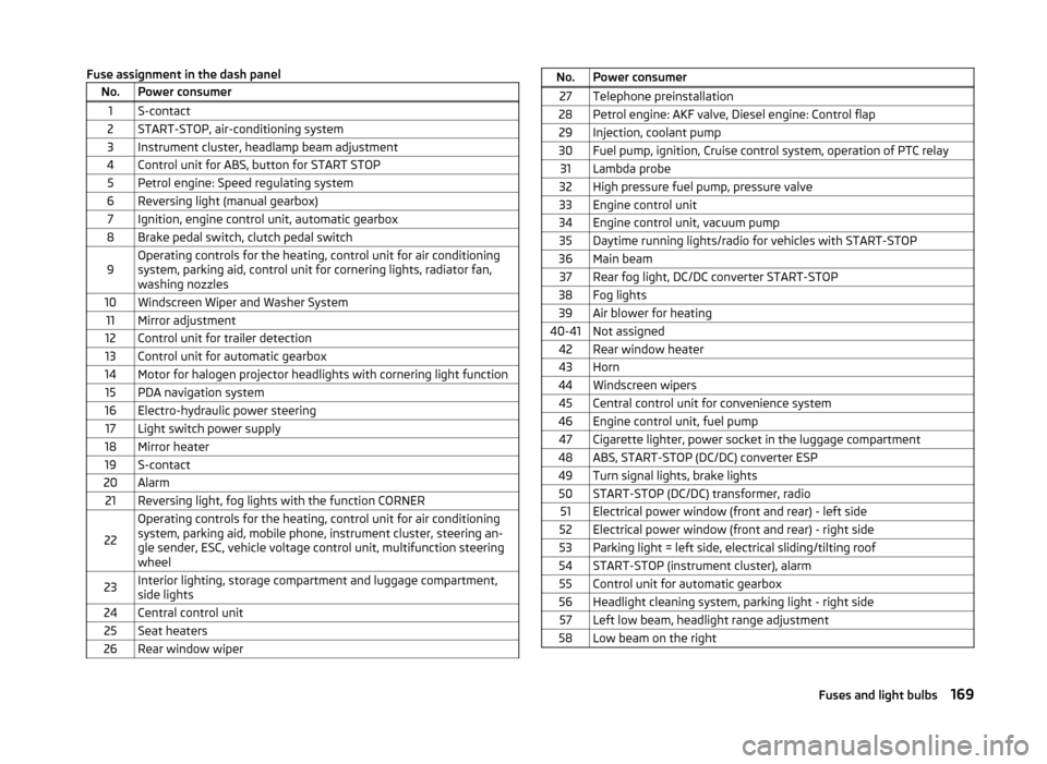
Fuse assignment in the dash panelNo.Power consumer1S-contact2START-STOP, air-conditioning system3Instrument cluster, headlamp beam adjustment4Control unit for ABS, button for START STOP5Petrol engine: Speed regulating system6Reversing light (manual gearbox)7Ignition, engine control unit, automatic gearbox8Brake pedal switch, clutch pedal switch9Operating controls for the heating, control unit for air conditioning
system, parking aid, control unit for cornering lights, radiator fan,
washing nozzles10Windscreen Wiper and Washer System11Mirror adjustment12Control unit for trailer detection13Control unit for automatic gearbox14Motor for halogen projector headlights with cornering light function15PDA navigation system16Electro-hydraulic power steering17Light switch power supply18Mirror heater19S-contact20Alarm21Reversing light, fog lights with the function CORNER
22
Operating controls for the heating, control unit for air conditioning
system, parking aid, mobile phone, instrument cluster, steering an-
gle sender, ESC, vehicle voltage control unit, multifunction steering
wheel23Interior lighting, storage compartment and luggage compartment,
side lights24Central control unit25Seat heaters26Rear window wiperNo.Power consumer27Telephone preinstallation28Petrol engine: AKF valve, Diesel engine: Control flap29Injection, coolant pump30Fuel pump, ignition, Cruise control system, operation of PTC relay31Lambda probe32High pressure fuel pump, pressure valve33Engine control unit34Engine control unit, vacuum pump35Daytime running lights/radio for vehicles with START-STOP36Main beam37Rear fog light, DC/DC converter START-STOP38Fog lights39Air blower for heating40-41Not assigned42Rear window heater43Horn44Windscreen wipers45Central control unit for convenience system46Engine control unit, fuel pump47Cigarette lighter, power socket in the luggage compartment48ABS, START-STOP (DC/DC) converter ESP49Turn signal lights, brake lights50START-STOP (DC/DC) transformer, radio51Electrical power window (front and rear) - left side52Electrical power window (front and rear) - right side53Parking light = left side, electrical sliding/tilting roof54START-STOP (instrument cluster), alarm55Control unit for automatic gearbox56Headlight cleaning system, parking light - right side57Left low beam, headlight range adjustment58Low beam on the right169Fuses and light bulbs
Page 172 of 197
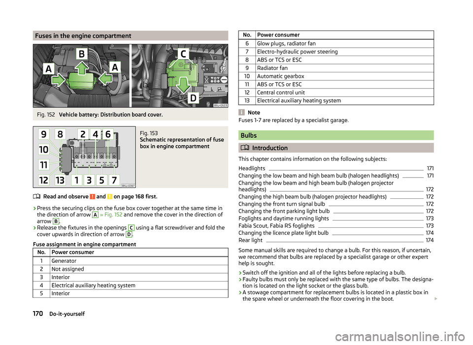
Fuses in the engine compartmentFig. 152
Vehicle battery: Distribution board cover.
Fig. 153
Schematic representation of fuse
box in engine compartment
Read and observe and on page 168 first.
› Press the securing clips on the fuse box cover together at the same time in
the direction of arrow
A
» Fig. 152 and remove the cover in the direction of
arrow
B
.
› Release the fixtures in the openings
C
using a flat screwdriver and fold the
cover upwards in direction of arrow
D
.
Fuse assignment in engine compartment
No.Power consumer1Generator2Not assigned3Interior4Electrical auxiliary heating system5InteriorNo.Power consumer6Glow plugs, radiator fan7Electro-hydraulic power steering8ABS or TCS or ESC9Radiator fan10Automatic gearbox11ABS or TCS or ESC12Central control unit13Electrical auxiliary heating system
Note
Fuses 1-7 are replaced by a specialist garage.
Bulbs
Introduction
This chapter contains information on the following subjects:
Headlights
171
Changing the low beam and high beam bulb (halogen headlights)
171
Changing the low beam and high beam bulb (halogen projector
headlights)
172
Changing the high beam bulb (halogen projector headlights)
172
Changing the front turn signal bulb
172
Changing the front parking light bulb
172
Foglights and daytime running lights
173
Fabia Scout, Fabia RS foglights
173
Changing the licence plate light bulb
174
Rear light
174
Some manual skills are required to change a bulb. For this reason, if uncertain,
we recommend that bulbs are replaced by a specialist garage or other expert
help is sought.
› Switch off the ignition and all of the lights before replacing a bulb.
› Faulty bulbs must only be replaced with the same type of bulbs. The designa-
tion is located on the light socket or the glass bulb.
› A stowage compartment for replacement bulbs is located in a plastic box in
the spare wheel or underneath the floor covering in the boot.
170Do-it-yourself
Page 190 of 197
Refuelling136
Unleaded petrol136
fuel consumption177
Fuel consumption109
Fuses Assignment
168
Changing168
Colour coding168
G
Gear Recommended gear
28
Gearbox Display messages
34
Gear changing Gear stick
104
General view Cockpit
25
Glow plug system Warning light
39
GSM92
H
Handbrake
104
Hazard warning light system59
Head airbag17
Headlight cleaning system Headlight cleaning system
63
Headlights171
Driving abroad113
Headlight cleaning system63
Head restraint68
Storing in the seat squabs68
Heating Deicing the windows
87
Exterior mirrors64
Operating86
Operation86
Rear window61
Recirculated air mode87
Seats66
Heating and air conditioning84
Hill hold control114
Horn25
I
Ignition
102
Ignition lock102
Immobilizer101
Individual settings locking
46
unlocking46
Inertia reel13
Instrument cluster26
Overview26
see instrument cluster26
Interior monitor50
ISOFIX22
J
Jack
159
Maintenance132
Jacking points Raise vehicle
161
Jump-starting164, 165
L
Light Beam adjustment
56
Cockpit59
Headlight flash57
Lights55
Cockpit60
Daylight running56
Fog lights58
Foglights with the CORNER function58
Halogen projector headlights with cornering light function
57
Hazard warning light system59
Low beam lights56
Main beam lights57
Parking lights56, 59
Rear fog light58
Replacing bulbs170
Switching on and off56
Tourist lights58
Turn signals57
warning lights35
Lock Central locking system
47
Locking Emergency locking
45
Remote control48
without central locking45
Locking and unlocking from the inside47
Low beam lights56
Luggage compartment Class N1 vehicles
69
Lighting61
Retractable luggage compartment cover (Fabia Estate)
71
Variable loading floor72
M
Main beam
57
Maintenance111
Decorative films131
Manual air conditioning Recirculated air mode
89
Manual gear changing see Gear changing
104
MAXI DOT Main menu
33
see MAXI DOT display33
Settings34
MAXI DOT display33
maximum allowable weights
176
188Index