charging SKODA FABIA 2014 2.G / 5J Owner's Manual
[x] Cancel search | Manufacturer: SKODA, Model Year: 2014, Model line: FABIA, Model: SKODA FABIA 2014 2.G / 5JPages: 197, PDF Size: 13.56 MB
Page 7 of 197
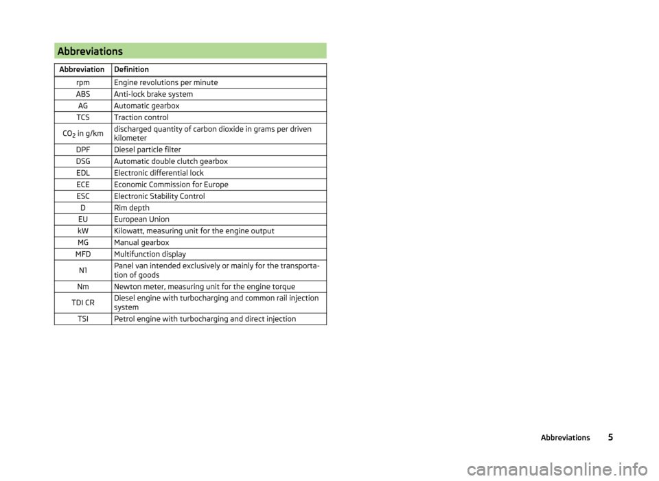
AbbreviationsAbbreviationDefinitionrpmEngine revolutions per minuteABSAnti-lock brake systemAGAutomatic gearboxTCSTraction controlCO2 in g/kmdischarged quantity of carbon dioxide in grams per driven
kilometerDPFDiesel particle filterDSGAutomatic double clutch gearboxEDLElectronic differential lockECEEconomic Commission for EuropeESCElectronic Stability ControlDRim depthEUEuropean UnionkWKilowatt, measuring unit for the engine outputMGManual gearboxMFDMultifunction displayN1Panel van intended exclusively or mainly for the transporta-
tion of goodsNmNewton meter, measuring unit for the engine torqueTDI CRDiesel engine with turbocharging and common rail injection
systemTSIPetrol engine with turbocharging and direct injection5Abbreviations
Page 62 of 197
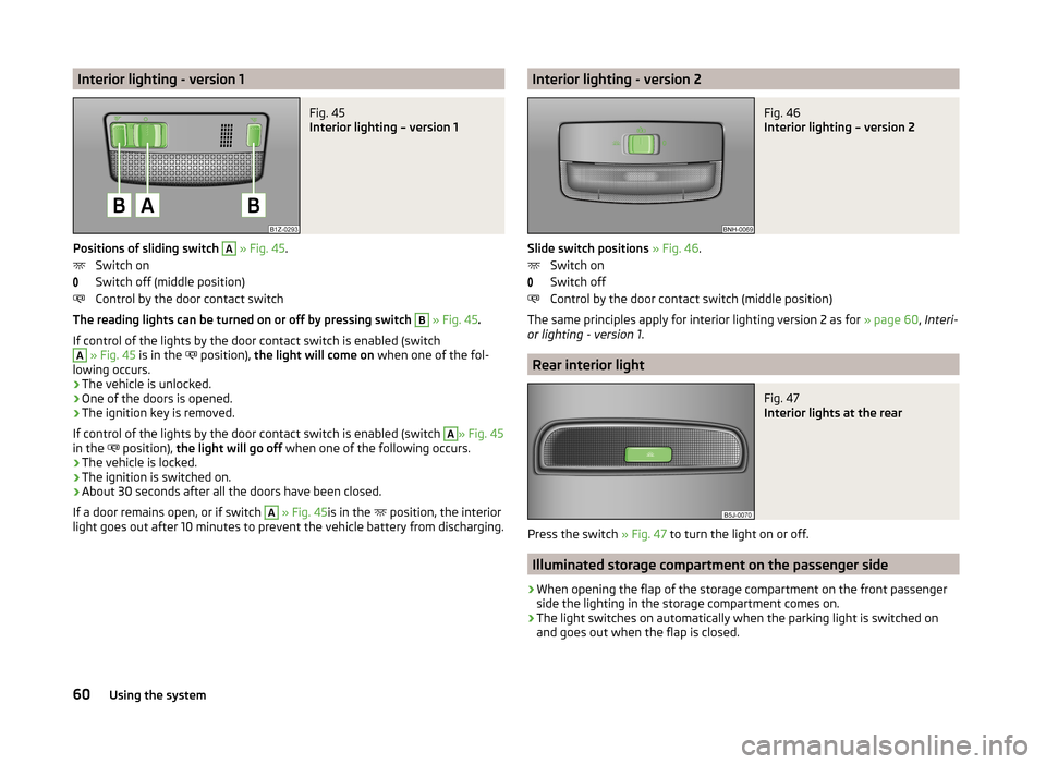
Interior lighting - version 1Fig. 45
Interior lighting – version 1
Positions of sliding switch
A
» Fig. 45 .
Switch on
Switch off (middle position)
Control by the door contact switch
The reading lights can be turned on or off by pressing switch
B
» Fig. 45 .
If control of the lights by the door contact switch is enabled (switch
A
» Fig. 45 is in the
position),
the light will come on when one of the fol-
lowing occurs.
› The vehicle is unlocked.
› One of the doors is opened.
› The ignition key is removed.
If control of the lights by the door contact switch is enabled (switch
A
» Fig. 45
in the position),
the light will go off when one of the following occurs.
› The vehicle is locked.
› The ignition is switched on.
› About 30 seconds after all the doors have been closed.
If a door remains open, or if switch
A
» Fig. 45 is in the
position, the interior
light goes out after 10 minutes to prevent the vehicle battery from discharging.
Interior lighting - version 2Fig. 46
Interior lighting – version 2
Slide switch positions » Fig. 46 .
Switch on
Switch off
Control by the door contact switch (middle position)
The same principles apply for interior lighting version 2 as for » page 60, Interi-
or lighting - version 1 .
Rear interior light
Fig. 47
Interior lights at the rear
Press the switch » Fig. 47 to turn the light on or off.
Illuminated storage compartment on the passenger side
›
When opening the flap of the storage compartment on the front passenger
side the lighting in the storage compartment comes on.
›
The light switches on automatically when the parking light is switched on
and goes out when the flap is closed.
60Using the system
Page 82 of 197
■Connecting electrical components when the engine is not running will drain
the battery of the vehicle – there is a risk of the battery discharging.■
Only use matching plugs to avoid damaging the power socket.
■
Only use accessories that have been tested for electromagnetic compatibility
in accordance with the applicable directives.
■
Switch off the devices connected to the power sockets before you switch
the ignition on or off and before starting the engine, to avoid damage from
voltage fluctuations.
■
Observe the operating instructions for the connected devices!
Clothes hook
Read and observe
on page 78 first.
The clothes hooks are located on the handle of the headliner above each of
the rear doors.
WARNING■ Ensure that any clothes hanging from the hooks do not impair your vision
to the rear.■
Only use the hooks for hanging light items of clothing and ensure that
there are no heavy or sharp-edged objects in the pockets.
■
Do not use clothes hangers for hanging up items of clothing otherwise
this may reduce the effectiveness of head airbags.
CAUTION
The maximum permissible load of the hooks is 2 kg.
Car park ticket holder
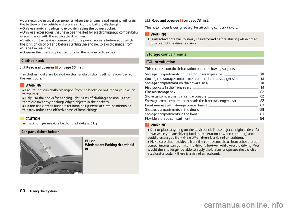
Fig. 82
Windscreen: Parking ticket hold-
er
Read and observe on page 78 first.
The note holder is designed e.g. for attaching car park tickets.
WARNINGThe attached note has to always be removed before starting off in order
not to restrict the driver's vision.
Storage compartments
Introduction
This chapter contains information on the following subjects:
Storage compartments on the front passenger side
81
Cooling the storage compartment on the front passenger side
81
Storage compartment on the driver's side
81
Map pockets in the front seats
81
Glasses storage box
82
Stowage compartment in centre console
82
Stowage compartment underneath the front passenger seat
82
Front armrest with storage compartment
83
Storage compartments in the doors
83
Storage compartments in the boot
83
Flexible storage compartment
84WARNING■ Do not place anything on the dash panel. These objects might slide or fall
down while you are driving (under acceleration or when cornering) and
could distract you from the traffic - there is a risk of an accident.■
Make sure that no objects from the centre console or from other storage
compartments can get into the driver's footwell while you are driving. You
would then no longer be able to apply the brakes or operate the clutch or
accelerator pedal – there is a risk of an accident.
80Using the system
Page 95 of 197
WARNING (Continued)■The national regulations for using a mobile phone in a vehicle must be
observed.■
If a mobile phone or a two-way radio system is operated in a vehicle with-
out an external aerial or an external aerial which has been installed incor-
rectly, this can increase the strength of the electromagnetic field inside the
vehicle.
■
Two-way radio systems, mobile phones or mounts must not be installed
on airbag covers or within the immediate deployment range of the airbags.
■
Never leave a mobile phone on a seat, on the dash panel or in another
area, from which it can be thrown during a sudden braking manoeuvre, an
accident or a collision - risk of injury.
■
The Bluetooth ®
function must be switched off by a specialist workshop
before the vehicle is transported by air.
Note
■ We recommend that mobile phones and two-way radio systems be installed
in the a vehicle by a specialist workshop.■
Not all mobile phones that enable Bluetooth ®
communication are compatible
with the universal telephone preinstallation GSM II. You can ask a ŠKODA Part-
ner whether your telephone is compatible with the GSM II universal telephone
fitting.
■
The range of the Bluetooth ®
connection to the hands-free system is restric-
ted to the vehicle interior. The range is dependent on local factors, e.g. obsta-
cles between the devices and mutual interferences with other devices. If your
mobile phone is in a jacket pocket, for example, this can lead to difficulties
when establishing a connection with the hands-free-system or transferring
data.
Introductory information
The universal telephone preinstallation GSM II (hands-free system) includes a
convenience mode for the mobile phone via voice control, the multifunction
steering wheel, the adapter, radio or the navigation system.
The universal telephone preinstallation GSM II comprises the following func-
tions.
› Phone Phonebook
» page 93.
› Convenience operation of the telephone via the multifunction steering
wheel » page 94 .
›Managing telephone calls via the adapter
» page 95.
› Telephone operation in the MAXI DOT display
» page 96.
› Voice control of the telephone
» page 97.
› Music playback from the telephone or other multimedia units
» page 98.
All communication between a mobile phone and your vehicle's hands-free sys-
tem is established with the help of Bluetooth ®
technology. The adapter serves
only for charging the telephone and for transmitting the signal to the vehicle's
external aerial.
Note
The following guidelines must be observed » page 92, Mobile phones and two-
way radio systems .
Phone Phonebook
A phone phonebook is part of the hands-free system. This phone phonebook
can be used depending on the type of mobile phone.
After the first connection of the telephone, the system begins to load the
phone book from the phone and the SIM card into the memory of the control
unit.
Each time the telephone has established a new connection with the hands-
free system, an update of the relevant phone book is performed. The updating
can take a few minutes. During this time the phone book, which was stored af-
ter the last update was completed, is available. Newly stored telephone num-
bers are only shown after the updating has ended.
The update is interrupted if a telephone event (e.g. incoming or outgoing call,
voice control dialogue) occurs during the updating procedure. After the tele-
phone event has ended, the updating starts anew.
The internal phonebook provides 2 500 free memory locations. Each contact can contain up to 4 numbers.
If the number of contacts loaded exceeds 2 500, the phone book is not com-
plete.
93Communication and multimedia
Page 97 of 197
CAUTIONTaking the mobile phone out of the adapter during the call can lead to inter-
ruption of the connection. When removing the mobile phone, the connection
to the factory-fitted antenna is interrupted, which reduces the quality of the
transmitting and receiving signal. The charging of the mobile phone battery is
also interrupted.
Managing telephone calls with the help of the adapter
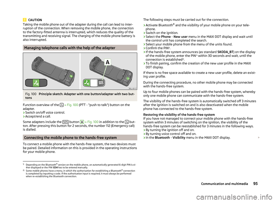
Fig. 100
Principle sketch: Adapter with one button/adapter with two but-
tons
Function overview of the
» Fig. 100 (PTT - “push to talk”) button on the
adapter.
› Switch on/off voice control.
› Accept/end a call.
Some adapters include the SOS
button
A
» Fig. 100 in addition to the but-
ton. After pressing this button for 2 seconds, the number 112 (Emergency call)
is dialled.
Connecting the mobile phone to the hands-free system
To connect a mobile phone with the hands-free system, the two devices must
be paired. Detailed information on this is provided in the operating instructions
for your mobile phone.
The following steps must be carried out for the connection.›
Activate Bluetooth ®
and the visibility of your mobile phone on your tele-
phone.
›
Switch on the ignition.
›
Select the Phone - New user menu in the MAXI DOT display and wait until
the control unit has completed the search.
›
Select your mobile phone from the menu of the units found.
›
Confirm the PIN 1)
.
›
If the hands-free system announces (as standard SKODA_BT) on the display
of the mobile phone, enter the PIN 1 )
within 30 seconds and wait, until the
connection is established 2)
.
›
To finish pairing, confirm the creation of the new user profile in the MAXI
DOT display.
If there is no free space available to create a new user profile, delete an exist-
ing user profile.
During the connecting procedure, no other mobile phone may be connected
with the hands-free system.
Up to four mobile phones can be paired with the hands-free system, whereby
only one mobile phone can communicate with the hands-free system.
The visibility of the hands-free system is automatically switched off 3 minutes
after the ignition is switched on and is also deactivated when the mobile
phone has connected to the hands-free system.
Restoring the visibility of the hands-free system
If you have not managed to connect your mobile phone with the hands-free
system within 3 minutes of switching on the ignition, the visibility of the
hands-free system can be reestablished for 3 minutes in the following ways.
› By turning the ignition off and on.
› By turning voice control off and on.
› In the
Bluetooth - Visibility menu in the MAXI DOT display.
1)
Depending on the Bluetooth®
version on the mobile phone, an automatically generated 6-digit PIN is ei-
ther displayed or the PIN 1234 has to be entered manually.
2)
Some mobile phones have a menu, in which the authorisation for establishing a Bluetooth ®
connection
is completed by inputting a code. If the authorisation input is required, it must always be performed
when re-establishing the Bluetooth connection.
95Communication and multimedia
Page 147 of 197
Do not use an alternative additive if the specified coolant is not available in an
emergency. In this case, use just water and have the correct mixing ratio of
water and coolant additive restored by a specialist garage as soon as possible.
Brake fluid
Introduction
This chapter contains information on the following subjects:
Level check
145
Changing
145WARNING■ The engine compartment of your car is a hazardous area. While working in
the engine compartment, be sure to observe the following warn-
ings » page 138 .■
Do not continue your journey if the fluid level has fallen below the MIN
marking » Fig. 130 on page 145 - there is a risk of an accident. Seek help
from a specialist garage.
■
Do not use used brake fluid - the function of the brake system may be im-
paired – there is the risk of an accident.
CAUTION
Brake fluid damages the paintwork of the vehicle.
Note
■ The brake fluid is changed as part of a prescribed inspection service.■We recommend using oils from the ŠKODA Original Accessories range.
Level check
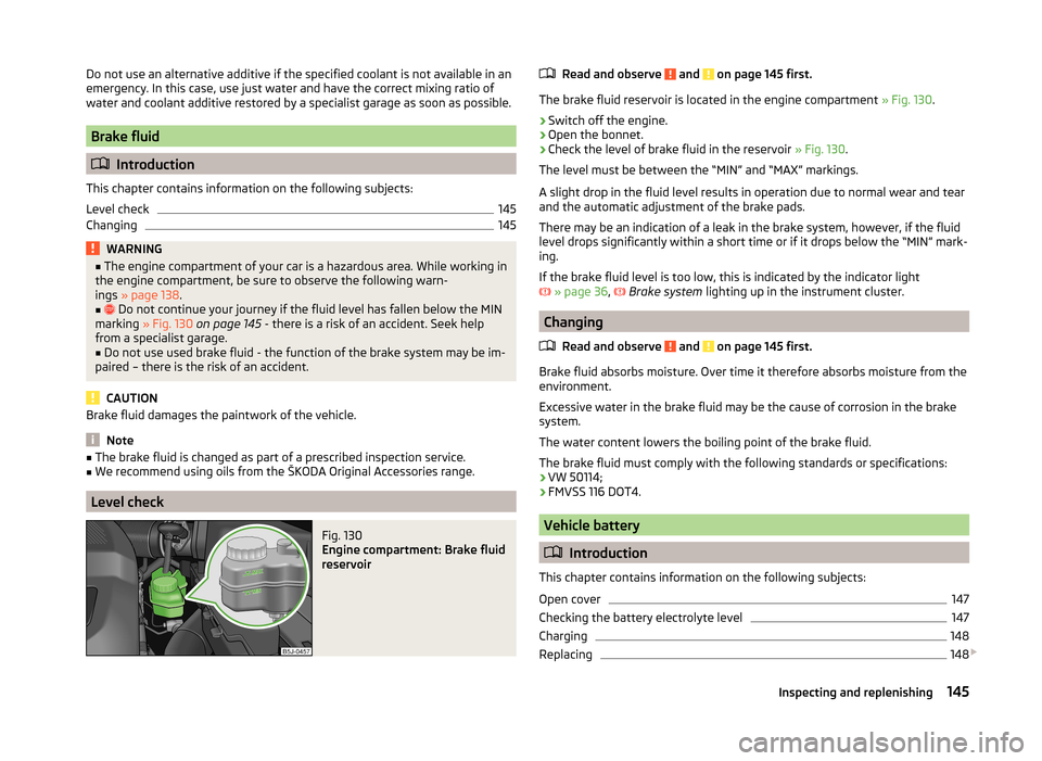
Fig. 130
Engine compartment: Brake fluid
reservoir
Read and observe and on page 145 first.
The brake fluid reservoir is located in the engine compartment » Fig. 130.
›
Switch off the engine.
›
Open the bonnet.
›
Check the level of brake fluid in the reservoir » Fig. 130.
The level must be between the “MIN” and “MAX” markings.
A slight drop in the fluid level results in operation due to normal wear and tear
and the automatic adjustment of the brake pads.
There may be an indication of a leak in the brake system, however, if the fluid level drops significantly within a short time or if it drops below the “MIN” mark-
ing.
If the brake fluid level is too low, this is indicated by the indicator light
» page 36 ,
Brake system
lighting up in the instrument cluster.
Changing
Read and observe
and on page 145 first.
Brake fluid absorbs moisture. Over time it therefore absorbs moisture from theenvironment.
Excessive water in the brake fluid may be the cause of corrosion in the brake
system.
The water content lowers the boiling point of the brake fluid.
The brake fluid must comply with the following standards or specifications: › VW 50114;
› FMVSS 116 DOT4.
Vehicle battery
Introduction
This chapter contains information on the following subjects:
Open cover
147
Checking the battery electrolyte level
147
Charging
148
Replacing
148
145Inspecting and replenishing
Page 148 of 197
Disconnecting or reconnecting148
Automatic load deactivation
149
Warning symbols on the vehicle battery
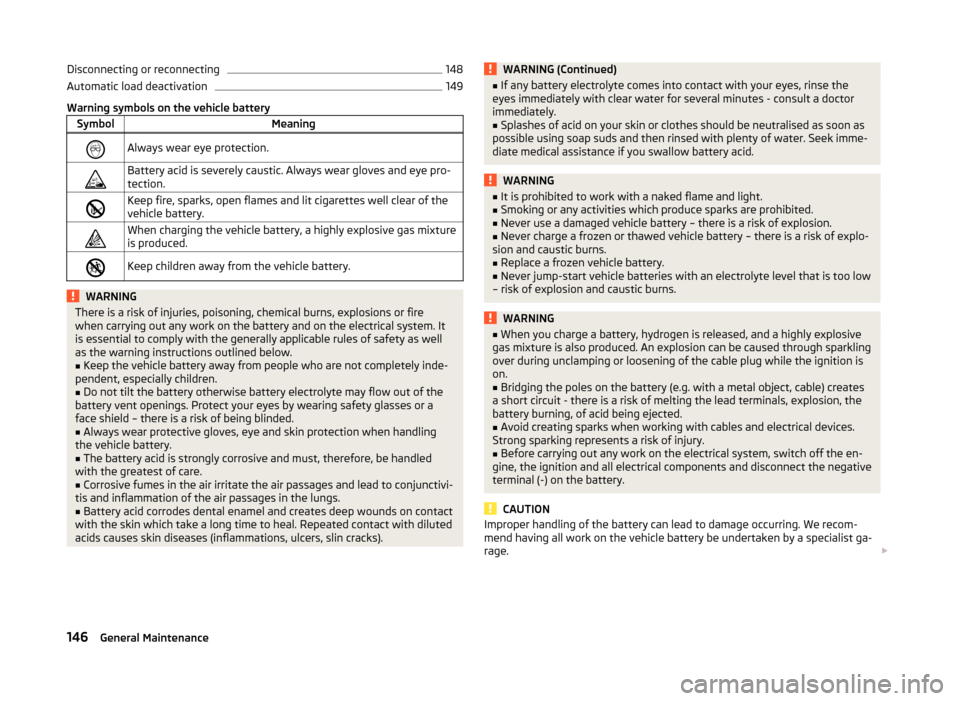
SymbolMeaningAlways wear eye protection.Battery acid is severely caustic. Always wear gloves and eye pro-
tection.Keep fire, sparks, open flames and lit cigarettes well clear of the
vehicle battery.When charging the vehicle battery, a highly explosive gas mixture
is produced.Keep children away from the vehicle battery.WARNINGThere is a risk of injuries, poisoning, chemical burns, explosions or fire
when carrying out any work on the battery and on the electrical system. It
is essential to comply with the generally applicable rules of safety as well
as the warning instructions outlined below.■
Keep the vehicle battery away from people who are not completely inde-
pendent, especially children.
■
Do not tilt the battery otherwise battery electrolyte may flow out of the
battery vent openings. Protect your eyes by wearing safety glasses or a
face shield – there is a risk of being blinded.
■
Always wear protective gloves, eye and skin protection when handling
the vehicle battery.
■
The battery acid is strongly corrosive and must, therefore, be handled
with the greatest of care.
■
Corrosive fumes in the air irritate the air passages and lead to conjunctivi-
tis and inflammation of the air passages in the lungs.
■
Battery acid corrodes dental enamel and creates deep wounds on contact
with the skin which take a long time to heal. Repeated contact with diluted
acids causes skin diseases (inflammations, ulcers, slin cracks).
WARNING (Continued)■ If any battery electrolyte comes into contact with your eyes, rinse the
eyes immediately with clear water for several minutes - consult a doctor
immediately.■
Splashes of acid on your skin or clothes should be neutralised as soon as
possible using soap suds and then rinsed with plenty of water. Seek imme-
diate medical assistance if you swallow battery acid.
WARNING■ It is prohibited to work with a naked flame and light.■Smoking or any activities which produce sparks are prohibited.■
Never use a damaged vehicle battery – there is a risk of explosion.
■
Never charge a frozen or thawed vehicle battery – there is a risk of explo-
sion and caustic burns.
■
Replace a frozen vehicle battery.
■
Never jump-start vehicle batteries with an electrolyte level that is too low
– risk of explosion and caustic burns.
WARNING■ When you charge a battery, hydrogen is released, and a highly explosive
gas mixture is also produced. An explosion can be caused through sparkling
over during unclamping or loosening of the cable plug while the ignition is
on.■
Bridging the poles on the battery (e.g. with a metal object, cable) creates
a short circuit - there is a risk of melting the lead terminals, explosion, the
battery burning, of acid being ejected.
■
Avoid creating sparks when working with cables and electrical devices.
Strong sparking represents a risk of injury.
■
Before carrying out any work on the electrical system, switch off the en-
gine, the ignition and all electrical components and disconnect the negative
terminal (-) on the battery.
CAUTION
Improper handling of the battery can lead to damage occurring. We recom-
mend having all work on the vehicle battery be undertaken by a specialist ga-
rage. 146General Maintenance
Page 149 of 197
CAUTION■The vehicle battery must only be disconnected if the ignition is switched off,
otherwise the vehicle's electrical system (electronic components) can be dam-
aged. When disconnecting the battery from the electrical system, first of all
disconnect the negative terminal (-) of the battery, followed by the positive
terminal (+).■
When connecting the battery to the electrical system, first of all connect the
positive terminal (+) of the battery, followed by the negative terminal (-). Under
no circumstances must the battery cables be connected incorrectly – risk of a
cable fire.
■
Ensure that battery acid does not come into contact with the bodywork –
there is a risk of damage to the paintwork.
■
Do not place the battery in direct daylight in order to protect the vehicle bat-
tery housing from the effects of ultra-violet light.
■
If the vehicle has not been driven for more than 3 to 4 weeks, the battery will
discharge. This is because certain electrical components consume electricity
(e. g. control units) also in idle state. Prevent the battery from discharging by
disconnecting the battery's negative terminal (-) or continuously charging the
battery with a very low charging current.
■
If the vehicle is frequently used for making short trips, the vehicle battery
will not have time to charge up sufficiently and may discharge.
For the sake of the environment
A vehicle battery that has been removed is a special type of hazardous waste.
These must be disposed of in accordance with national legal regulations.
Note
You should replace batteries older than 5 years.
Open cover
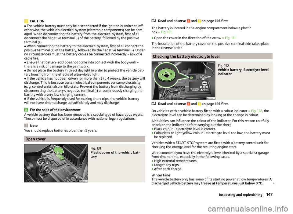
Fig. 131
Plastic cover of the vehicle bat-
tery
Read and observe and on page 146 first.
The battery is located in the engine compartment below a plastic
box » Fig. 131 .
›
Open the cover in the direction of the arrow » Fig. 131.
The installation of the battery cover on the positive terminal side takes place
in the reverse order.
Checking the battery electrolyte level
Fig. 132
Vehicle battery: Electrolyte level
indicator
Read and observe and on page 146 first.
On vehicles with a vehicle battery fitted with a colour indicator » Fig. 132, the
electrolyte level can be determined by looking at the change in colour.
Air bubbles can influence the colour of the indicator. For this reason carefully knock on the indicator before carrying out the check.
› Black colour - electrolyte level is correct.
› Colourless or light yellow colour - electrolyte level too low, the battery must
be replaced.
Vehicles with a START-STOP system are fitted with a battery control unit for
checking the energy level for the recurring engine start.
We recommend you have the electrolyte level checked by a specialist garage from time to time, especially in the following cases.
› High external temperatures.
› Longer day trips.
› After each charge.
Winter time
The vehicle battery only has some of its starting power at low temperatures. A
discharged vehicle battery may freeze at temperatures just below 0 °C .
147Inspecting and replenishing
Page 150 of 197
We therefore recommend that you have the battery checked and, if necessary,
recharged by a specialist garage before the start of the winter.
CAUTION
For technical reasons, on vehicles with the description “AGM”, the electrolyte
level cannot be checked.
Note
The battery electrolyte level is also periodically checked by a specialist garage
as part of the Inspection Service.
Charging
Read and observe
and on page 146 first.
A properly charged vehicle battery is essential for reliably starting the engine.
›
Switch off the ignition and all of the electrical components.
›
Only when performing a “quick-charge”, disconnect both battery cables (first
“negative”, then “positive”).
›
Attach the terminal clamps of the charger to the battery terminals (red =
“positive”, black = “negative”).
›
Plug the mains cable of the charger into the power socket and switch the
charger on.
›
Once charging is complete: Switch off the charger and remove the mains ca-
ble from the power socket.
›
Only then disconnect the charger's terminal clamps.
›
Reconnect the cables to the battery (first “positive”, then “negative”).
It is not necessary to disconnect the battery cables if you are recharging the
vehicle battery using low amperages (for example from a mini-charger). Refer
to the charger manufacturer's instructions .
A charging current of 0.1 multiple of the total vehicle battery capacity (or low-
er) must be used until full charging is achieved.
Both cables must be disconnected before charging the battery with high
amperages, known as “ rapid charging”.
The vent plugs of the vehicle battery should not be opened for charging.
WARNING“Quick-charging” the vehicle battery is dangerous and requires a special
charger and specialist knowledge.CAUTIONOn vehicles with the START/STOP system, the pole terminal of the charger
must not be connected directly to the negative terminal of the vehicle battery,
but only to the engine earth » page 166, Jump-starting in vehicles with the
START-STOP system .
Note
We therefore recommend that vehicle batteries be rapid charged by a special-
ist garage.
Replacing
Read and observe
and on page 146 first.
The new vehicle battery must have the same capacity, voltage, current and thesame size as the original battery. Suitable vehicle battery types can be pur-
chased from a specialist garage.
We recommend that the battery is replaced by a specialist garage, where the
new vehicle battery will be installed properly and the original battery will be
disposed of in accordance with national regulations.
Disconnecting or reconnecting
Read and observe
and on page 146 first.
The following functions are initially deactivated or are no longer able to oper-
ate faultlessly after the vehicle battery has been disconnected and reconnec-
ted.
OperationOperating measureElectrical power window (operational faults)» page 53Enter the radio/navigation system code
number» User manual of the radio
or » user manual of the naviga-
tion systemSetting the clock» page 28Data in the multifunction display are de-
leted.» page 29
Note
We recommend having the vehicle checked by a specialist garage to ensure
the full functionality of all electrical systems.148General Maintenance
Page 151 of 197
Automatic load deactivationRead and observe
and on page 146 first.
The vehicle voltage control unit automatically prevents the battery from dis-
charging when the battery is subjected to heavy loads. This may be noticed
from the following.
› The idling speed is raised to allow the generator to deliver more electricity to
the electrical system.
› Where appropriate large convenience consumers, e.g. seat heaters, rear win-
dow heaters, have their power limited or shut off completely if necessary.
CAUTION
■ Despite such intervention by the vehicle electric system management, the
vehicle battery may be drained. For example, when the ignition is switched on
a long time with the engine turned off or the side or parking lights are turned
on during longer parking.■
Consumers which are supplied via a 12 V socket can cause the vehicle battery
to discharge when the ignition is switched off.
Note
Driving comfort is not disrupted by any shutting off of consumers. Often the
driver is not aware of it having taken place.Wheels
Tyres and rims
Introduction
This chapter contains information on the following subjects:
Tyre service life
151
Explanation of the tire labelling
152
New Wheels
152
Unidirectional tyres
154
Tyre pressure monitor
154
Spare and back-up wheel
155
Full wheel trim
156
Wheel bolts
156
Wheel bolts
156WARNINGNational legal requirements must be observed for the use of tyres.WARNINGInstructions for the use of tyres■During the first 500 km, new tyres do not offer optimum grip and appro-
priate care should therefore be taken when driving – there is the risk of an
accident.■
Only use radial tyres of the same type, size and tread pattern on all four
wheels.
■
For safety reasons, do no replace tyres individually.
■
Never exceed the maximum permissible load bearing capacity for fitted
tyres – risk of accident!
■
Never exceed the maximum permissible speed for fitted tyres – risk of ac-
cident!
■
Incorrect wheel alignment at the front or rear impairs handling – there is
the risk of an accident.
149Wheels