bulb SKODA FABIA 2014 2.G / 5J Owner's Manual
[x] Cancel search | Manufacturer: SKODA, Model Year: 2014, Model line: FABIA, Model: SKODA FABIA 2014 2.G / 5JPages: 197, PDF Size: 13.56 MB
Page 6 of 197
Do-it-yourself
Emergency equipment, and self-help158
Emergency equipment
158
Changing a wheel
159
Tyre repair
162
Jump-starting
164
Towing the vehicle
166
Fuses and light bulbs
168
Fuses
168
Bulbs
170
Technical data
Technical data
176
Vehicle data
176
Index
4Table of Contents
Page 37 of 197
The following message is shown in the MAXI DOT display.Gearbox overheated. Stop. Log book!
Stop the vehicle, switch off the engine, and wait until the
icon goes out –
there is a risk of gearbox damage. You can continue your journey as soon as
the icon disappears.WARNINGIf you have to stop for technical reasons, park the vehicle at a safe distance
from the traffic, switch off the engine and activate the hazard warning light
system » page 59 .
Note
■
Warning messages shown in the MAXI DOT display must be confirmed with
button B » Fig. 24 on page 33 to call up the main menu.■
As long as the operational faults are not rectified, the symbols are always in-
dicated again. After they are displayed for the first time, the symbols continue
to be indicated without any extra messages for the driver.
Warning lights
Introduction
This chapter contains information on the following subjects:
Handbrake
35
Brake system
36
Seat belt warning light
36
Generator
36
OPen door
36
Engine oil
36
Coolant
37
Power steering
38
Electronic Stability Control (ESC)
38
Traction Control System (ASR)
38
Antilock brake system (ABS)
38
The rear fog light
39
Bulb failure
39
Exhaust inspection system
39
Glow plug system (diesel engine)
39 EPC fault light (petrol engine)39 Diesel particulate filter (diesel engine)39
Fuel reserve
40
Airbag system
40
Tyre pressure
41
Windscreen washer fluid level
41
Traction control (TCS) switched off
41
Turn signal system
41
Low beam
41
Fog lights
41
Cruise control system
41
Selector lever lock
42
Main beam
42
The warning lights show certain functions/faults and may be accompanied by
audible signals.
WARNING■ If illuminated warning lights and the corresponding descriptions and
warning notes are not observed, this may result in severe injuries or major
vehicle damage.■
The engine compartment of your car is a hazardous area. There is a risk of
injuries, scalding, accidents and fire when working in the engine compart-
ment, e.g. inspecting and replenishing oil and other fluids. It is essential to
observe safety notes » page 138, Engine compartment .
Handbrake
Read and observe
on page 35 first.
The warning light comes on if the handbrake is applied. An audible warning
is also given if you drive the vehicle for at least 3 seconds at a speed of more
than 6 km/h.
The following message is shown in the MAXI DOT display. Release parking brake!
35Instruments and Indicator Lights
Page 41 of 197
The following message is shown in the MAXI DOT display.Error: ABS
The vehicle will only be braked by the normal brake system without the ABS.
Seek help from a specialist garage.WARNING■ If you have to stop for technical reasons, then park the vehicle at a safe
distance from the traffic, switch off the engine and activate the hazard
warning light system » page 59.■
If the warning light
» page 36 is displayed simultaneously with the ABS
warning light
,
do not continue your journey! Seek help from a special-
ist garage.
■
A fault to the ABS system or the braking system can increase the vehi-
cle's braking distance – there is a risk of accident.
The rear fog light
Read and observe
on page 35 first.
The warning light comes on when the rear fog lights are operat-
ing » page 58 .
Bulb failure
Read and observe
on page 35 first.
The warning light comes on if a bulb is faulty:
› within a few seconds of the ignition being switched on;
› when a light with a defective bulb is switched on.
The following message may be shown in the MAXI DOT display, for example. INFORMATION Check front right low beam!
Note
The rear side lights and the licence plate lighting have several light bulbs. The
indicator light only lights up if all light bulbs of the licence plate lighting or
the parking light (in one rear light) are defective. For this reason, regular check
that these light bulbs are working correctly. Exhaust inspection system
Read and observe
on page 35 first.
If the warning light
lights up, there is a fault in the exhaust inspection sys-
tem. The engine control unit allows the vehicle to run in emergency mode.
Seek help from a specialist garage.
Glow plug system (diesel engine)
Read and observe
on page 35 first.
The warning light comes on after the ignition has been switched on. The
engine can be started immediately after the pre-glow warning light goes out.
There is a fault in the glow plug system if the warning light
does not come
on at all or lights up continuously .
If the warning light begins to
flash while driving, a fault exists in the engine
control. The engine control unit allows the vehicle to run in emergency mode.
Seek help from a specialist garage.
EPC fault light (petrol engine)
Read and observe
on page 35 first.
If the warning light comes on or begins to flash while driving, a fault exists
in the engine control unit. The engine control unit allows the vehicle to run in
emergency mode.
Seek help from a specialist garage.
Diesel particulate filter (diesel engine)
Read and observe
on page 35 first.
The diesel particulate filter separates the soot particles from the exhaust. The soot particles collect in the diesel particulate filter where they are burnt on a
regular basis.
The warning light comes on if soot has accumulated in the filter.
39Instruments and Indicator Lights
Page 59 of 197
Activating on vehicles with the START-STOP system›Switch off the ignition.›
At the same time, pull the turn signal light stalk » Fig. 42 on page 57 to-
wards the steering wheel, push it upwards, and hold it in this position.
›
Switch on the ignition - wait until the right-turn signal light flashes 4x.
›
Switch off the ignition - an audible signal sounds which confirms the activa-
tion of the daylight driving lights.
›
Release the turn signal stalk.
On vehicles with separate lights for daylight driving lights in the fog lights or in
the front bumper, the parking lights and the licence plate light do not come on
when activating the function daylight driving lights (neither front nor rear).
If the vehicle is not equipped with separate lights for daylight driving lights,
the combination of the low beam, the parking lights (front and rear) including
the licence plate light is used as daylight driving lights.
Note
In vehicles with separate lights for daylight driving lights (in the bumper below
the main headlights) these lights also serve as side lights.
Turn signal and main beam lights
Fig. 42
Stalk: turn signal and main beam
operation
Read and observe on page 55 first.
The parking light is controlled with the control stalk » page 59.
Control stalk positions » Fig. 42 .
Switch on right turn signal
Switch on left turn signal
Switch on high beam (spring-loaded position)
Switch off main beam and headlamp flasher (spring-loaded position)
ABCDWhen the left or right turn signal is on, the
or warning light flashes in the
instrument cluster.
When the high beam or headlight flasher is on, the
warning light lights up in
the instrument cluster.
Turn signal for changing lanes - to flash only briefly, move the stalk up or
down to the pressure point only and hold it in this position.
Convenience turn signal
If you wish to flash three times only, briefly push the stalk to the upper or low-
er pressure point and release again.WARNINGOnly turn on the main beam or the headlight flasher if other road users will
not be dazzled.
Note
■ The main beam can only be switched on when the low beam lights are on.■The headlight flasher can be operated even if the ignition is switched off.■
The turn signal system only operates when the ignition is switched on.
■
The turn signal is automatically cancelled after negotiating a curve.
■
The warning light flashes at twice its normal rate if a bulb for the turn signal
light fails.
Halogen projector headlights with cornering light function
Read and observe
on page 55 first.
For a better cornering illumination, the halogen projector headlights with cor-
nering light function are set in the optimal position in line with the vehicle
speed and the steering angle.
WARNINGIf the halogen projector headlights with cornering light function are faulty,
the headlights are automatically lowered to the emergency position, which
prevents a possible dazzling of oncoming traffic. Thus the illuminated
length of the road is shortened. Drive carefully and visit a specialist garage
as soon as possible.57Lights and visibility
Page 129 of 197
Before you decide to have damaged body parts replaced, however, you should
first contact your specialist garage to determine whether or not such parts can
also be repaired. Repairs to body parts are usually cheaper.
ŠKODA Original Accessories
Read and observe
on page 126 first.
You should note the following if you wish to fit accessories to your vehicle:
We recommend that you use ŠKODA Genuine Accessories in your vehicle.
ŠKODA AUTO a.s. offers a warranty on the reliability, safety and suitability for
your particular vehicle of these accessories. Although we constantly monitor
the market, we are not able to assess or offer a warranty on other products
even though in some instances such products may have a type approval or
may have been approved by a nationally recognised approval authority.
All accessory products go through a fastidious process of technical develop-
ment (technical tests) and quality inspection (customer tests), and only if all
tests are positive does the product become a ŠKODA Genuine Accessory.
Our ŠKODA Genuine Accessories service also provides expert advice and pro-
fessional fitting if requested by the customer.
ŠKODA Service Partners are liable for any defects in ŠKODA Genuine Parts for a period of 2 years after installation or delivery in accordance with materials de-
fect liability legislation, unless otherwise agreed in the purchase contract or in
any other agreements. You should keep the confirmed warranty certificate and
the receipt for these accessories for this period, so that the commencement of
the warranty term may be verified.
In addition, ŠKODA Service Partners also stock a range of suitable car care
products as well as those parts which are subject to natural wear and tear,
such as tyres, batteries, bulbs and wiper blades.
Note
The accessories authorized by ŠKODA AUTO a.s. will be offered by the ŠKODA
Partners in all countries where ŠKODA AUTO a.s. has a sales and service net- work. This will usually be in the form of a printed catalogue of Original ŠKODA
Accessories, in the form of separate printed brochures or in the form of offers
for ŠKODA Genuine Accessories on the ŠKODA Partner's website.Spoiler
Read and observe
on page 126 first.
The following instructions shall be observed if your new vehicle is equippedwith a spoiler fitted to the front bumper in combination with the spoiler on the
tailgate.
› For safety reasons the vehicle must only ever be equipped with a spoiler on
the front bumper in combination with the associated spoiler on the tailgate.
› A spoiler cannot be fitted alone on the front bumper nor in combination with-
out a spoiler on the tailgate or in combination with an inappropriate spoiler
on the tailgate.
› We recommend that you consult a ŠKODA Service Partner for any repairs, re-
placement, fitting or removal of spoilers.
WARNINGWork not properly performed on the spoilers on your vehicle can result in
faults - there is a risk of an accident and serious injury.
Airbags
Read and observe
on page 126 first.
The system components for the airbag system may be found in the front
bumper, doors, front seats, the roof lining or in the bodywork.
WARNINGAny work on the airbag system including the installation and removal of
system components due to other repair work (e.g. removal of the steering
wheel) must only be carried out by a specialist garage.■
Adjustments, repairs and modifications which have been carried out un-
professionally can cause damage, operational faults, and can also seriously
impair the effectiveness of airbag system – there is the risk of an accident
and fatal injury.
■
The airbag system must be replaced if an airbag has been deployed. Air-
bag modules cannot be repaired.
127Car care
Page 161 of 197
Vehicle tool kitFig. 140
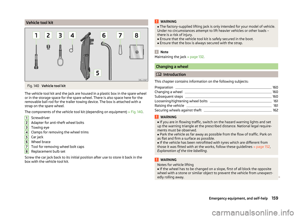
Vehicle tool kit
The vehicle tool kit and the jack are housed in a plastic box in the spare wheel
or in the storage space for the spare wheel. There is also space here for the
removable ball rod for the trailer towing device. The box is attached with a
strap on the spare wheel.
The components of the vehicle tool kit (depending on equipment) » Fig. 140.
Screwdriver
Adapter for anti-theft wheel bolts
Towing eye
Clamps for removing the wheel trims
Car jack
Wheel brace
Tool for removing wheel bolt caps
Replacement bulb set
Screw the car jack back to its initial position after use to store it back in the
box with the vehicle tool kit.
12345678WARNING■ The factory-supplied lifting jack is only intended for your model of vehicle.
Under no circumstances attempt to lift heavier vehicles or other loads –
there is a risk of injury.■
Ensure that the vehicle tool kit is safely secured in the boot.
■
Ensure that the box is always secured with the strap.
Note
Maintaining the jack » page 132.
Changing a wheel
Introduction
This chapter contains information on the following subjects:
Preparation
160
Changing a wheel
160
Subsequent steps
160
Loosening/tightening wheel bolts
161
Raising the vehicle
161
Securing wheels against theft
162WARNING■ If you are in flowing traffic, switch on the hazard warning lights and set
up the warning triangle at the prescribed distance. National legal require-
ments must be observed.■
Park the vehicle as far away as possible from the flow of traffic. Park on
as flat and firm a surface as possible.
■
If the vehicle has been retrofitted with tyres which are different from
those it was fitted with at the works, follow these guidelines » page 152,
Explanation of the tire labelling .
WARNINGNotes for vehicle lifting■If the wheel has to be changed on a slope, first of all block the opposite
wheel with a stone or similar object to prevent the vehicle from unexpect-
edly rolling away. 159Emergency equipment, and self-help
Page 170 of 197
Fuses and light bulbs
Fuses
Introduction
This chapter contains information on the following subjects:
Fuses in the dash panel
168
Fuses in the engine compartment
170
Individual electrical circuits are protected by fuses.
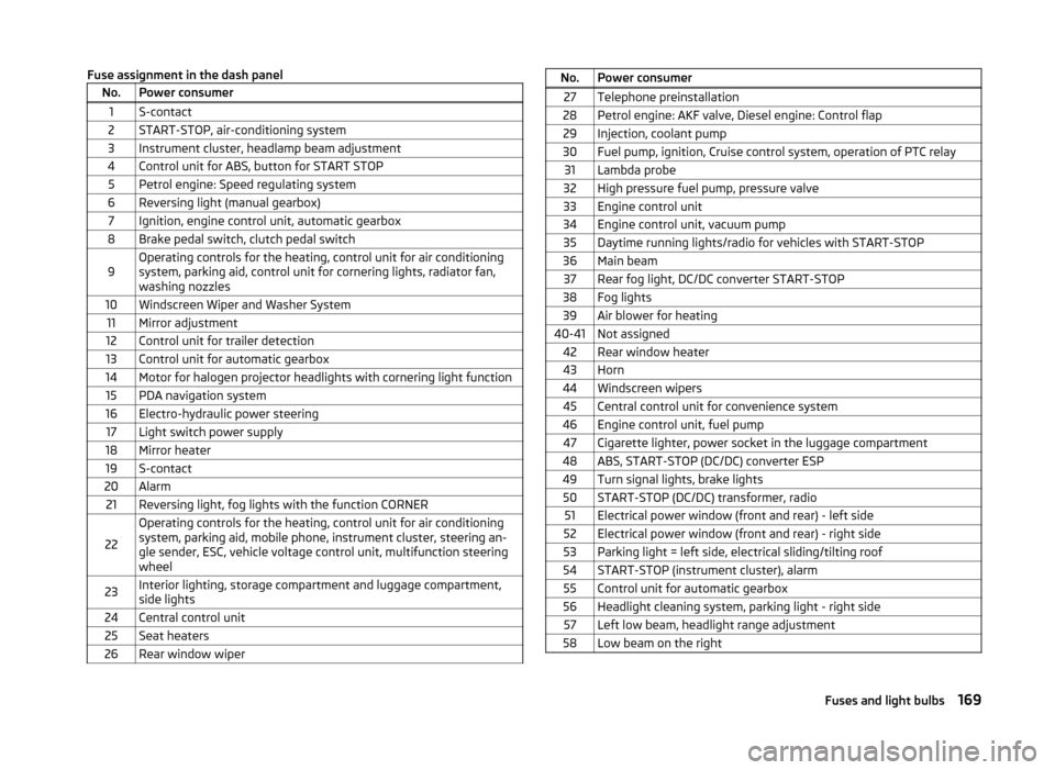
› Before replacing a fuse, switch off the ignition and the appropriate consumer
› Find out which fuse belongs to the component that is not operat-
ing » page 168 , Fuses in the dash panel or » page 170 , Fuses in the engine
compartment .
› Take the plastic clip out of its fixture in the cover of the fuse box, place it on
the relevant fuse and pull it out.
Fuse colourMaximum amperagelight brown5dark brown7.5red10blue15yellow20white25green30WARNINGAlways read and observe the warnings before completing any work in the
engine compartment » page 138.
CAUTION
■
“Never repair” fuses or replace them with a fuse of a higher amperage –
there is a risk of fire. This may also cause damage at another part of the elec-
trical system.■
Have the electrical system checked as quickly as possible by a specialist ga-
rage if a newly inserted fuse blows again after a short time.
■
A blown fuses is recognisable by the molten metal strip. Replace the faulty
fuse with a new one of the same amperage.
Note■
We recommend that you always carry replacement fuses in the vehicle. A box
of replacement fuses can be purchased from ŠKODA Original Accessories.■
One fuse may cover several consumers.
■
A single consumer may use several fuses.
Fuses in the dash panel
Fig. 150
Underside of the dash panel: Dis-
tribution board cover.
Fig. 151
Schematic representation of the fuse box for vehicles with left-
hand steering/right-hand steering
Read and observe
and on page 168 first.
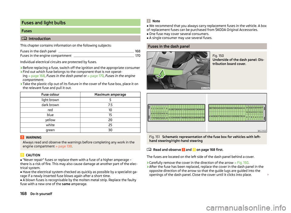
The fuses are located on the left side of the dash panel behind a cover.
› Carefully remove the cover in the direction of the arrow
» Fig. 150.
› After the fuse has been replaced, replace the cover in the dash panel in the
opposite direction of the arrow so that the guide lugs are guided into the
openings of the dash panel. Close the cover until it clicks into place.
168Do-it-yourself
Page 171 of 197
Fuse assignment in the dash panelNo.Power consumer1S-contact2START-STOP, air-conditioning system3Instrument cluster, headlamp beam adjustment4Control unit for ABS, button for START STOP5Petrol engine: Speed regulating system6Reversing light (manual gearbox)7Ignition, engine control unit, automatic gearbox8Brake pedal switch, clutch pedal switch9Operating controls for the heating, control unit for air conditioning
system, parking aid, control unit for cornering lights, radiator fan,
washing nozzles10Windscreen Wiper and Washer System11Mirror adjustment12Control unit for trailer detection13Control unit for automatic gearbox14Motor for halogen projector headlights with cornering light function15PDA navigation system16Electro-hydraulic power steering17Light switch power supply18Mirror heater19S-contact20Alarm21Reversing light, fog lights with the function CORNER
22
Operating controls for the heating, control unit for air conditioning
system, parking aid, mobile phone, instrument cluster, steering an-
gle sender, ESC, vehicle voltage control unit, multifunction steering
wheel23Interior lighting, storage compartment and luggage compartment,
side lights24Central control unit25Seat heaters26Rear window wiperNo.Power consumer27Telephone preinstallation28Petrol engine: AKF valve, Diesel engine: Control flap29Injection, coolant pump30Fuel pump, ignition, Cruise control system, operation of PTC relay31Lambda probe32High pressure fuel pump, pressure valve33Engine control unit34Engine control unit, vacuum pump35Daytime running lights/radio for vehicles with START-STOP36Main beam37Rear fog light, DC/DC converter START-STOP38Fog lights39Air blower for heating40-41Not assigned42Rear window heater43Horn44Windscreen wipers45Central control unit for convenience system46Engine control unit, fuel pump47Cigarette lighter, power socket in the luggage compartment48ABS, START-STOP (DC/DC) converter ESP49Turn signal lights, brake lights50START-STOP (DC/DC) transformer, radio51Electrical power window (front and rear) - left side52Electrical power window (front and rear) - right side53Parking light = left side, electrical sliding/tilting roof54START-STOP (instrument cluster), alarm55Control unit for automatic gearbox56Headlight cleaning system, parking light - right side57Left low beam, headlight range adjustment58Low beam on the right169Fuses and light bulbs
Page 172 of 197
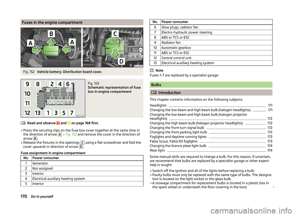
Fuses in the engine compartmentFig. 152
Vehicle battery: Distribution board cover.
Fig. 153
Schematic representation of fuse
box in engine compartment
Read and observe and on page 168 first.
› Press the securing clips on the fuse box cover together at the same time in
the direction of arrow
A
» Fig. 152 and remove the cover in the direction of
arrow
B
.
› Release the fixtures in the openings
C
using a flat screwdriver and fold the
cover upwards in direction of arrow
D
.
Fuse assignment in engine compartment
No.Power consumer1Generator2Not assigned3Interior4Electrical auxiliary heating system5InteriorNo.Power consumer6Glow plugs, radiator fan7Electro-hydraulic power steering8ABS or TCS or ESC9Radiator fan10Automatic gearbox11ABS or TCS or ESC12Central control unit13Electrical auxiliary heating system
Note
Fuses 1-7 are replaced by a specialist garage.
Bulbs
Introduction
This chapter contains information on the following subjects:
Headlights
171
Changing the low beam and high beam bulb (halogen headlights)
171
Changing the low beam and high beam bulb (halogen projector
headlights)
172
Changing the high beam bulb (halogen projector headlights)
172
Changing the front turn signal bulb
172
Changing the front parking light bulb
172
Foglights and daytime running lights
173
Fabia Scout, Fabia RS foglights
173
Changing the licence plate light bulb
174
Rear light
174
Some manual skills are required to change a bulb. For this reason, if uncertain,
we recommend that bulbs are replaced by a specialist garage or other expert
help is sought.
› Switch off the ignition and all of the lights before replacing a bulb.
› Faulty bulbs must only be replaced with the same type of bulbs. The designa-
tion is located on the light socket or the glass bulb.
› A stowage compartment for replacement bulbs is located in a plastic box in
the spare wheel or underneath the floor covering in the boot.
170Do-it-yourself
Page 173 of 197
WARNING■Always read and observe the warnings before completing any work in the
engine compartment » page 138.■
Accidents can be caused if the road in front of the vehicle is not suffi-
ciently illuminated and the vehicle cannot or can only be seen with difficul-
ty by other road users.
■
Bulbs H7 and H4 are pressurised and may burst when changed - there is a
risk of injury. We therefore recommended wearing gloves and safety
glasses when changing a bulb.
■
Switch off the respective vehicle light when changing the bulb.
CAUTION
■ Do not take hold of the glass bulb with naked fingers (even the smallest
amount of dirt reduces the working life of the light bulb). Use a clean cloth,
napkin, or similar.■
When removing and installing the number plate light and tail light make sure
that the paintwork of the vehicle and the tail light are not damaged.
Note
■ This Owner's Manual only describes the replacement of bulbs where it is pos-
sible to replace the bulbs on your own without any complications arising. Other
light bulbs should be changed by your specialist garage.■
We recommend that you always carry a box of replacement bulbs in the vehi-
cle. Replacement bulbs can be purchased from ŠKODAOriginal Accessories.
■
We recommend having the headlight settings checked by a specialist garage
after replacing a bulb in the main beam, low beam or fog lights.
■
Visit a specialist garage if an LED is faulty.
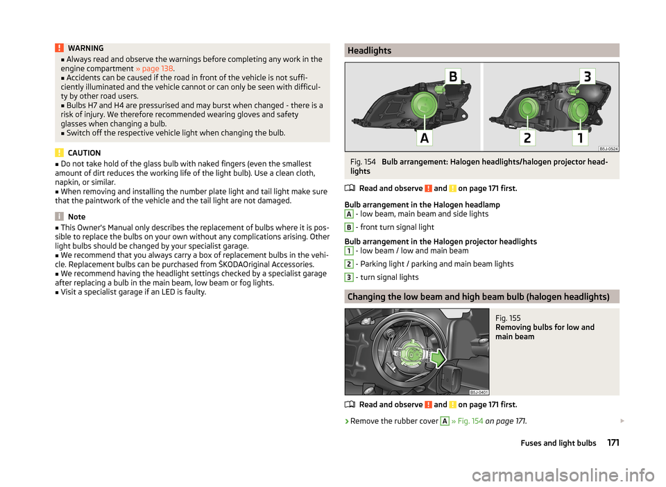
HeadlightsFig. 154
Bulb arrangement: Halogen headlights/halogen projector head-
lights
Read and observe
and on page 171 first.
Bulb arrangement in the Halogen headlamp
A
- low beam, main beam and side lights
B
- front turn signal light
Bulb arrangement in the Halogen projector headlights
1
- low beam / low and main beam
2
- Parking light / parking and main beam lights
3
- turn signal lights
Changing the low beam and high beam bulb (halogen headlights)
Fig. 155
Removing bulbs for low and
main beam
Read and observe and on page 171 first.
›
Remove the rubber cover
A
» Fig. 154 on page 171 .
171Fuses and light bulbs