remote control SKODA FABIA 2014 2.G / 5J Owner's Manual
[x] Cancel search | Manufacturer: SKODA, Model Year: 2014, Model line: FABIA, Model: SKODA FABIA 2014 2.G / 5JPages: 197, PDF Size: 13.56 MB
Page 5 of 197
Table of Contents
Abbreviations
Safety
Passive Safety
6
General information
6
Correct and safe seated position
7
Seat belts
10
Wearing seat belts
10
Inertia reel and belt pretensioners
13
Airbag system
14
Description of the airbag system
14
Airbag overview
15
Deactivating airbags
17
Transporting children safely
19
Child seat
19
Fastening systems
22
Using the system
Cockpit
25
Overview
24
Instruments and Indicator Lights
26
Instrument cluster
26
Multifunction display (MFD)
29
Service Interval Display
32
MAXI DOT display
33
Warning lights
35
Unlocking and locking
42
Unlocking and locking
42
Central locking system
45
Remote control
48
Anti-theft alarm system
49
Tailgate
50Electrical power windows51Electric sliding/tilting roof53
Lights and visibility
55
Lights
55
Interior lights
59
Visibility
61
Windscreen wipers and washers
61
Rear window
63
Seats and storage
65
Front seats
65
Rear seats
66
Head restraints
67
Boot
68
Variable loading floor in the luggage
compartment (Fabia Estate)
72
Net partition (Fabia Estate)
73
Bicycle carrier in the luggage compartment
75
Roof rack system
76
Useful equipment
77
Storage compartments
80
Heating and air conditioning
84
Heating, ventilation, cooling
84
Heating
86
Air conditioning system (manual air
conditioning system)
87
Climatronic (automatic air conditioning
system)
90
Communication and multimedia
92
Universal telephone preinstallation GSM II
92
Voice control
97
Multimedia
98
Driving
Starting-off and Driving
101
Starting and stopping the engine
101
Brakes
102Manual gear shifting and pedals104Automatic transmission105
Running in
108
Economical driving and respect the
environment
109
Avoiding damage to your vehicle
112
Driving abroad
113
Assist systems
114
Brake assist systems
114
Parking aid
116
Cruise control system
117
START-STOP
118
Towing a trailer
120
Towing device
120
Trailer
124
General Maintenance
Car care
126
Services, modifications and technical
alterations
126
Washing the car
128
Vehicle exterior care
129
Care of the interior
132
Inspecting and replenishing
135
Fuel
135
Engine compartment
138
Engine oil
141
Coolant
143
Brake fluid
145
Vehicle battery
145
Wheels
149
Tyres and rims
149
Winter use
1563Table of Contents
Page 27 of 197
Using the system
Cockpit
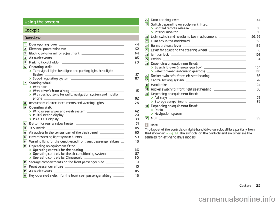
OverviewDoor opening lever
44
Electrical power windows
52
Electric exterior mirror adjustment
64
Air outlet vents
85
Parking ticket holder
80
Operating stalk:
› Turn signal light, headlight and parking light, headlight
flasher
57
› Speed regulating system
117
Steering wheel:
› With horn
› With driver’s front airbag
15
›With pushbuttons for radio, navigation system and mobile
phone
92
Instrument cluster: Instruments and warning lights
26
Operating stalk:
› Windscreen wiper and wash system
62
›Multifunction display
29
›MAXI DOT display
33
Button for rear window heater
61
TCS switch
115
Air outlets in the central part of the dash panel
85
Hazard warning light system button
59
Warning light for the deactivated front seat passenger airbag
18
Depending on equipment fitted:
› Operating controls for the heating
86
›Operating controls for the air conditioning system
87
›Operating controls for Climatronic
90
Storage compartments on the front passenger side
81
Front passenger airbag
15
Air outlet vents
85
Key-operated switch for the front seat passenger airbag
1812345678910111213141516171819Door opening lever44
Switch depending on equipment fitted:
› Boot lid remote release
50
›Interior monitor
50
Light switch and headlamp beam adjustment
56, 56
Fuse box in the dashboard
168
Bonnet release lever
139
Lever for adjusting the steering wheel
8
Ignition lock
102
Pedals
104
Depending on equipment fitted:
› Gearshift lever (manual gearbox)
104
›Selector lever (automatic gearbox)
105
Rocker switch for front left seat heating
66
Central locking system
47
Handbrake
104
Rocker switch for front right seat heating
66
Depending on equipment fitted:
› Ashtrays
78
›Storage compartment
82
Depending on equipment fitted:
› Radio
› Navigation system
MDI
99
Note
The layout of the controls on right-hand drive vehicles differs partially from
that shown in » Fig. 18. The symbols on the controls and switches are the
same as for left-hand drive models.2021222324252627282930313233343525Cockpit
Page 44 of 197
Selector lever lockRead and observe
on page 35 first.
If the warning light
lights up, operate the brake pedal. This is necessary to
be able to move the selector lever from position P or N » page 106 .
Main beam
Read and observe
on page 35 first.
The warning light
comes on when the main beam or headlight flasher are
selected » page 57 .
Unlocking and locking
Unlocking and locking
Introduction
This chapter contains information on the following subjects:
Vehicle key
42
Replacing the battery in the remote control key
43
Child safety lock
44
Opening/closing the door
44
Locking/unlocking the vehicle without central locking
45
Emergency locking of the doors
45
Vehicle key
Fig. 25
Key: without/with remote control
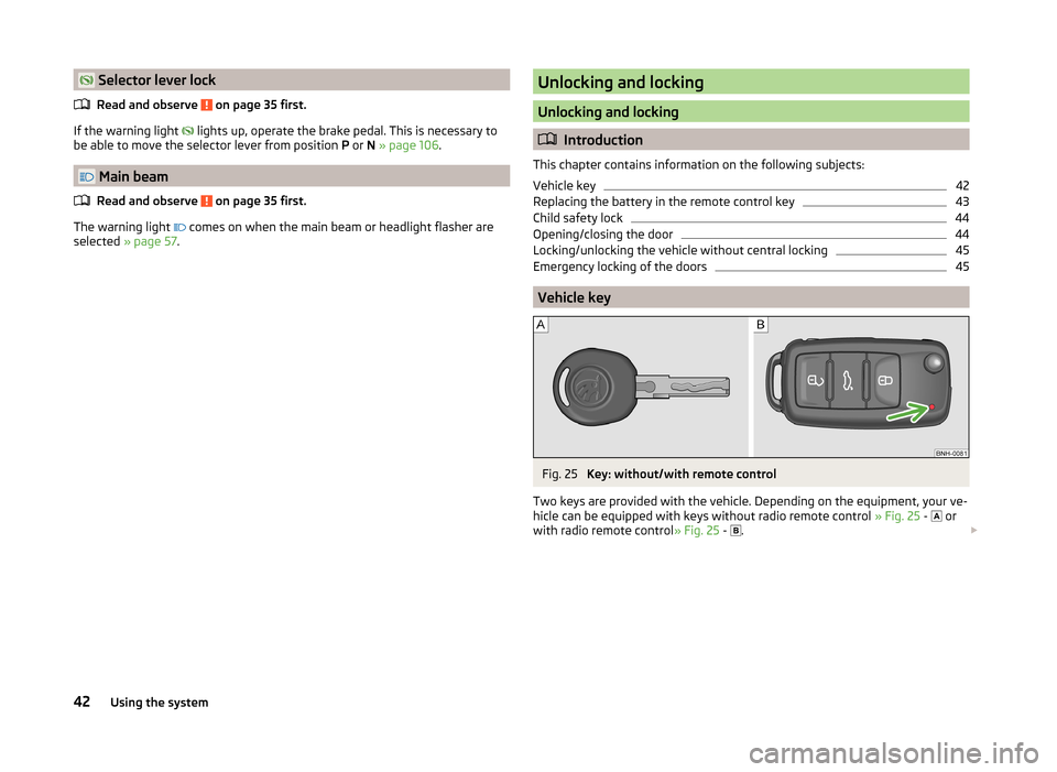
Two keys are provided with the vehicle. Depending on the equipment, your ve-
hicle can be equipped with keys without radio remote control » Fig. 25 -
or
with radio remote control » Fig. 25 -
.
42Using the system
Page 45 of 197
WARNING■Never leave the key in the vehicle when you exit the vehicle. Unauthor-
ized persons, such as children, for example, could lock the car, turn on the
ignition or start the engine - there is the danger of injury and accidents oc-
curring!■
When leaving the vehicle, never leave people who are not completely in-
dependent, such as children, unattended in the vehicle. The children might,
for example, release the handbrake or take the vehicle out of gear. The
vehicle could then start to move – risk of accident! These individuals would
possibly not be able to leave the vehicle on their own or to help them-
selves. At very high or very low temperatures can be fatal!
CAUTION
■ Each key contains electronic components; therefore it must be protected
against moisture and severe shocks.■
Keep the groove of the keys absolutely clean. Impurities (textile fibres, dust,
etc.) have a negative effect on the functionality of the locking cylinder and ig-
nition lock.
■
Operation of the remote control may temporarily be affected by interference
from transmitters close to the car operating in the same frequency range (e.g.
mobile phone, TV transmitter).
■
The battery must be replaced if the central locking only reacts to the remote
control at less than 3 metres away » page 43.
Note
■
When leaving the vehicle, always check if this is locked.■Please contact a specialist garage if you lose a key as they can obtain a new
one for you.Replacing the battery in the remote control keyFig. 26
Remote control key: Remove cover/remove battery
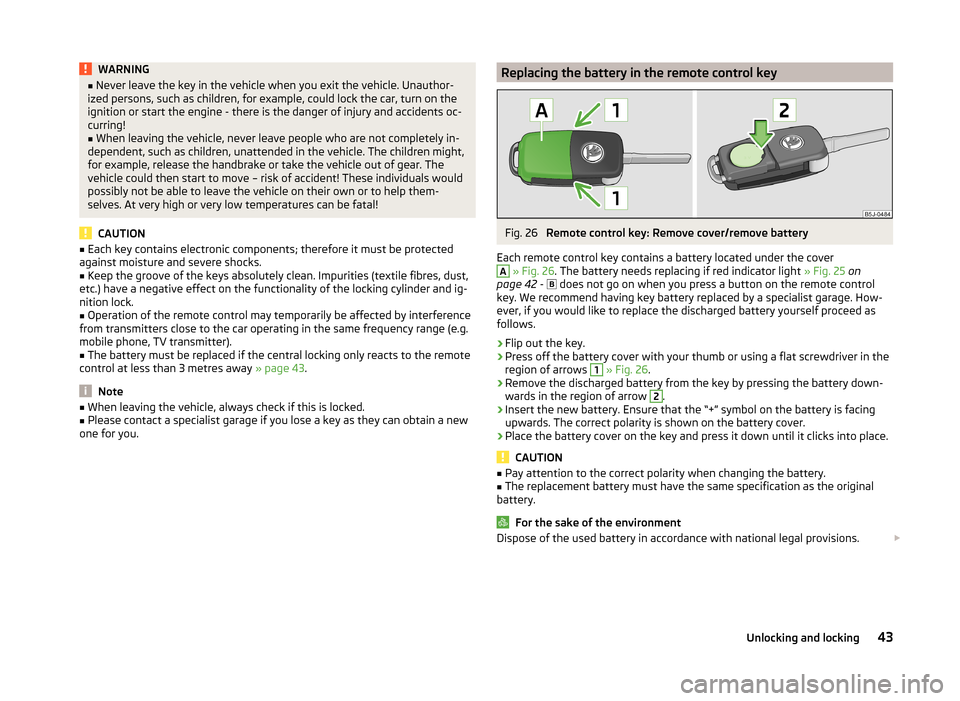
Each remote control key contains a battery located under the cover
A
» Fig. 26 . The battery needs replacing if red indicator light » Fig. 25 on
page 42 -
does not go on when you press a button on the remote control
key. We recommend having key battery replaced by a specialist garage. How-
ever, if you would like to replace the discharged battery yourself proceed as
follows.
›
Flip out the key.
›
Press off the battery cover with your thumb or using a flat screwdriver in the
region of arrows
1
» Fig. 26 .
›
Remove the discharged battery from the key by pressing the battery down-
wards in the region of arrow
2
.
›
Insert the new battery. Ensure that the “+” symbol on the battery is facing upwards. The correct polarity is shown on the battery cover.
›
Place the battery cover on the key and press it down until it clicks into place.
CAUTION
■ Pay attention to the correct polarity when changing the battery.■The replacement battery must have the same specification as the original
battery.
For the sake of the environment
Dispose of the used battery in accordance with national legal provisions. 43Unlocking and locking
Page 46 of 197
Note■The system has to be synchronised, if the vehicle cannot be unlocked or
locked with the remote control key after replacing the battery » page 49.■
Replacing the battery in the key a glued decorative cover requires the cover
to be destroyed. A replacement cover can be purchased from a ŠKODA Partner.
Child safety lock
Fig. 27
Switching child safety lock on: for vehicles without or with central
locking system
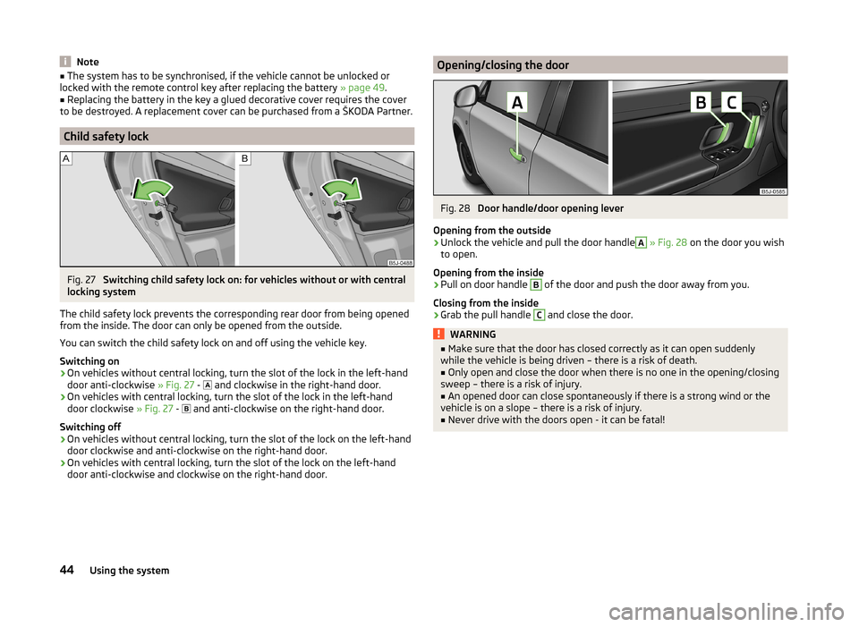
The child safety lock prevents the corresponding rear door from being opened
from the inside. The door can only be opened from the outside.
You can switch the child safety lock on and off using the vehicle key.
Switching on
›
On vehicles without central locking, turn the slot of the lock in the left-hand
door anti-clockwise » Fig. 27 -
and clockwise in the right-hand door.
›
On vehicles with central locking, turn the slot of the lock in the left-hand
door clockwise » Fig. 27 -
and anti-clockwise on the right-hand door.
Switching off
›
On vehicles without central locking, turn the slot of the lock on the left-hand
door clockwise and anti-clockwise on the right-hand door.
›
On vehicles with central locking, turn the slot of the lock on the left-hand
door anti-clockwise and clockwise on the right-hand door.
Opening/closing the doorFig. 28
Door handle/door opening lever
Opening from the outside
›
Unlock the vehicle and pull the door handle
A
» Fig. 28 on the door you wish
to open.
Opening from the inside
›
Pull on door handle
B
of the door and push the door away from you.
Closing from the inside
›
Grab the pull handle
C
and close the door.
WARNING■ Make sure that the door has closed correctly as it can open suddenly
while the vehicle is being driven – there is a risk of death.■
Only open and close the door when there is no one in the opening/closing
sweep – there is a risk of injury.
■
An opened door can close spontaneously if there is a strong wind or the
vehicle is on a slope – there is a risk of injury.
■
Never drive with the doors open - it can be fatal!
44Using the system
Page 50 of 197
›If at least one door has been opened, the vehicle cannot be locked.
› In the event of an accident in which the airbags are deployed, the locked
doors are automatically unlocked in order to enable rescuers to gain access
to the vehicle.WARNING■ Doors locked from the inside make it difficult for rescuers to get into the
vehicle in an emergency – danger to life!■
If the safelock system is switched on » page 46, the door opening lever
and the central locking buttons do not operate.
Remote control
Introduction
This chapter contains information on the following subjects:
Unlocking/locking
48
Synchronization
49
You can use the remote control key to:
› unlock and lock the vehicle,
› unlocking boot lid;
› open and close the windows
» page 53, Window convenience operation .
The transmitter with the battery is housed in the handle of the remote control
key. The receiver is located in the interior of the vehicle. The operating range of the remote control key is approx. 30 m. But this range of the remote control
can be reduced if the batteries are weak.
The key has a fold-open key bit which can be used for unlocking and locking
the car manually and also for starting the engine.
The system must be initialised by a specialist garage if a lost key is replaced or
if the receiver unit has been repaired or replaced. Only then can the remote
control key be used again.
Note
■ The remote control is automatically deactivated when the ignition is switch-
ed on.■
Operation of the remote control may temporarily be affected by interference
from transmitters close to the car operating in the same frequency range (e.g.
mobile phone, TV transmitter).
■ The battery must be replaced if the central locking or anti-theft alarm system
does react to the remote control at less than 3 metres away » page 43.■
If the driver door is open, the vehicle cannot be locked using the remote con-
trol key.
Unlocking/locking
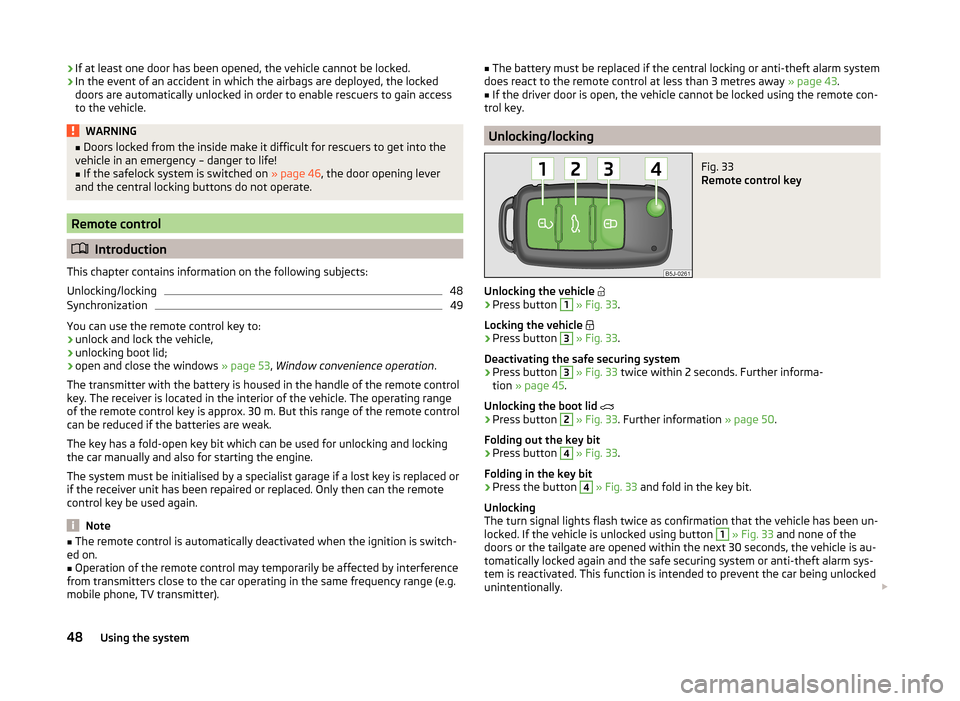
Fig. 33
Remote control key
Unlocking the vehicle
›
Press button
1
» Fig. 33 .
Locking the vehicle
›
Press button
3
» Fig. 33 .
Deactivating the safe securing system
›
Press button
3
» Fig. 33 twice within 2 seconds. Further informa-
tion » page 45 .
Unlocking the boot lid
›
Press button
2
» Fig. 33 . Further information » page 50.
Folding out the key bit
›
Press button
4
» Fig. 33 .
Folding in the key bit
›
Press the button
4
» Fig. 33 and fold in the key bit.
Unlocking
The turn signal lights flash twice as confirmation that the vehicle has been un-
locked. If the vehicle is unlocked using button
1
» Fig. 33 and none of the
doors or the tailgate are opened within the next 30 seconds, the vehicle is au-
tomatically locked again and the safe securing system or anti-theft alarm sys-
tem is reactivated. This function is intended to prevent the car being unlocked
unintentionally.
48Using the system
Page 51 of 197
In addition, when the car is unlocked, the electrically adjustable seats and ex-
terior mirrors move into the position assigned to this key. The stored setting of
driver seat and exterior mirrors is retrieved.
Locking
The turn signal lights flash once to confirm that the vehicle has been correctly
locked.
If the doors or the boot lid remain open after the vehicle has been locked, the
turn signal lights do not flash until they have been closed.
Note
■ Only operate the remote control when the doors and boot lid are closed and
the vehicle is in your line of sight.■
A ŠKODA partner can also activate/deactivate the acoustic signals on vehi-
cles with an anti-theft alarm system.
Synchronization
If the vehicle does not unlock when the remote control is pressed, the key may
not be synchronised. This can occur when the buttons on the remote control
key are pressed several times outside the operating range of the equipment or
if the battery in the remote control key has been replaced.
Synchronise the key as follows.
›
Press any button on the remote control key.
›
Unlock the door with the key within 1 minute of pressing the button.
Anti-theft alarm system
Introduction
This chapter contains information on the following subjects:
Operation
49
Interior monitor and towing protection
50
The anti-theft alarm system increases the level of protection against people
seeking to break into the vehicle. The system triggers audible and visual warn-
ing signals if an attempt is made to break into the vehicle.
Note■ The working life of the alarm siren is 5 years.■Before leaving the car, it must be checked that all of the windows, doors and
the electric sliding/tilting roof are properly closed to ensure the full functional-
ity of the anti-theft alarm system.■
Coding of the radio remote control and the receiver unit precludes the use of
the radio remote control from other vehicles.
Operation
How is the alarm system activated?
The anti-theft alarm system is activated when the vehicle is locked with the
radio remote control or the key in the driver's door . It is activated 30 seconds
after locking the door.
How is the alarm system deactivated?
The alarm system is deactivated by pressing the button on the remote con-
trol. The anti-theft alarm system is reactivated if the vehicle is not opened
within 30 seconds after transmitting the radio signal.
Triggering the alarm
The alarm is triggered when the following unauthorized actions are carried out
on the locked vehicle.
› Opening the bonnet.
› Opening the boot lid.
› Opening the doors.
› Manipulation of the ignition lock.
› Towing the vehicle
» page 50;
› Movement in the vehicle
» page 50.
› Sudden and significant voltage drop of the electrical system.
› Uncoupling the trailer
» page 125.
If the driver's door of a vehicle with a remote control is unlocked and opened
by the lock cylinder, then the alarm is triggered.
Switching off the alarm
The alarm is turned off by pressing the button on the radio remote control
key or switching on the ignition.
CAUTION
Before leaving the vehicle, it must be checked that all of the windows, doors
and the sliding/tilting roof are locked in order to ensure the full functionality of
the anti-theft alarm system.49Unlocking and locking
Page 53 of 197
Opening the boot lid for vehicles with central locking›Press the handle and open the tailgate in the direction of the arrow » Fig. 35
-
.
Closing›
Pull down the tailgate and close it with a gentle swing.
A handle which makes the closing easier is located on the inner panelling of
the boot lid.
Automatic locking of the boot lid
Read and observe
on page 50 first.
If the boot lid is unlocked with the key symbol on the remote control key,
then the door is automatically locked after closing.
The period after which the boot lid is locked automatically can be extended by
a specialist garage.
After the activation of the delayed locking, the door can be opened again after
closing within a limited period.
Delayed locking can be deactivated by a specialist garage at any time.
CAUTION
There is a risk of unwanted entry into the vehicle before the boot lid is locked
automatically. We therefore recommend locking the vehicle with the key sym-
bol
on the remote control key.
Emergency unlocking
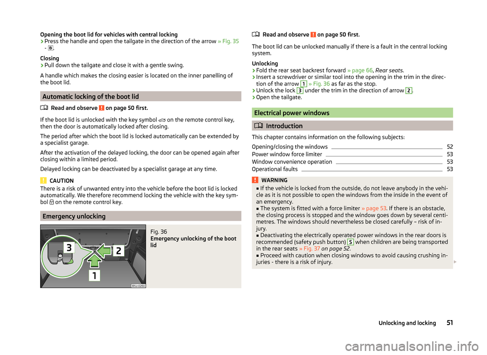
Fig. 36
Emergency unlocking of the boot
lid
Read and observe on page 50 first.
The boot lid can be unlocked manually if there is a fault in the central locking
system.
Unlocking
›
Fold the rear seat backrest forward » page 66, Rear seats .
›
Insert a screwdriver or similar tool into the opening in the trim in the direc-
tion of the arrow
1
» Fig. 36 as far as the stop.
›
Unlock the lock
3
under the trim in the direction of arrow
2
.
›
Open the tailgate.
Electrical power windows
Introduction
This chapter contains information on the following subjects:
Opening/closing the windows
52
Power window force limiter
53
Window convenience operation
53
Operational faults
53WARNING■ If the vehicle is locked from the outside, do not leave anybody in the vehi-
cle as it is not possible to open the windows from the inside in the event of
an emergency.■
The system is fitted with a force limiter » page 53. If there is an obstacle,
the closing process is stopped and the window goes down by several centi-
metres. The windows should nevertheless be closed carefully – risk of in-
jury.
■
Deactivating the electrically operated power windows in the rear doors is
recommended (safety push button)
S
when children are being transported
in the rear seats » Fig. 37 on page 52 .
■
Proceed with caution when closing windows to avoid causing crushing in-
juries - there is a risk of injury.
51Unlocking and locking
Page 55 of 197
Power window force limiterRead and observe
and on page 51 first.
The electrical power windows are fitted with a force limiter. It reduces the risk
of bruises or injuries when closing the windows.
If there is an obstacle, the closing process is stopped and the window goes
down by several centimetres.
If the obstacle prevents the window from being closed during the next 10 sec-
onds, the closing process is interrupted once again and the window goes down
by several centimetres.
If you attempt to close the window again within 10 seconds of the window be-
ing moved down for the second time, even though the obstacle was not yet
been removed, the closing process is only stopped. During this time it is not
possible to automatically close the window. The force limiter is still switched
on.
The force limiter is only switched off if you attempt to close the window again
within the next 10 seconds - the window will now close with full force!
If you wait longer than 10 seconds, the force limiter is switched on again.
Window convenience operation
Read and observe
and on page 51 first.
The comfort controls of the windows provide the ability to open or close all the
windows at once.
Opening can take place in one of the following ways.
Opening
›
Press the symbol button on the remote control key and hold.
›
Hold the key in the driver's lock in the unlock position.
›
Hold button
A
» Fig. 37 on page 52 in the opening position.
Closing
›
Press the symbol button on the remote control key and hold.
›
Hold the key in the driver's lock in the lock position.
›
Hold Button
A
» Fig. 37 on page 52 in the closing position.
The movement of the window is immediately stopped by releasing the key or
the respective button.
Operational faults
Read and observe
and on page 51 first.
Electrical power windows do not operate
If the battery has been disconnected and then reconnected while the window was opened, the electrical power windows will not operate. The system must
be activated. Proceed as follows to re-establish the function.
› Switch on the ignition.
› Pull the top edge of the button in the driver's door and close the window.
› Release the button.
› Pull the relevant button upwards again for another approximately 3 seconds
and hold.
Operation in winter
In the winter, ice on the window may cause greater resistance as the window
is closed. The window will stop and open again by several centimetres.
It is necessary to deactivate the force limiter to close the window » page 53.
Electric sliding/tilting roof
Introduction
This chapter contains information on the following subjects:
Operation
54
Comfort operation
54
Emergency operation
55
The sliding/tilting roof is operated with the rotary switch » Fig. 38 on
page 54 and only works when the ignition is switched on. The control dial
has several positions.
The sliding/tilting roof can still be opened, closed and tilted for approx. 10 mi-
nutes after switching the ignition off. However, as soon as one of the front
doors is opened it is no longer possible to operate the sliding/tilting roof.
WARNINGClose the sliding/tilting roof carefully – risk of injury. 53Unlocking and locking
Page 56 of 197
CAUTIONDuring the winter it may be necessary to remove any ice and snow in the vicin-
ity of the sliding/tilting roof before opening it to prevent any damage to the
opening mechanism and seal.
Note
If the battery has been disconnected and reconnected, it is possible that the
sliding/tilting roof does not close fully. This is why the rotary switch must be
set to position A
» Fig. 38 on page 54 and pressed forwards for about
10 seconds.
Operation
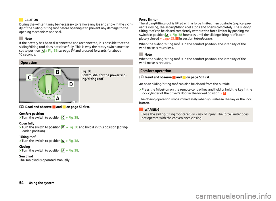
Fig. 38
Control dial for the power slid-
ing/tilting roof
Read and observe and on page 53 first.
Comfort position
›
Turn the switch to position
C
» Fig. 38 .
Open fully
›
Turn the switch to position
B
» Fig. 38 and hold it in this position (spring-
loaded position).
Tilting roof
›
Turn the switch to position
D
» Fig. 38 .
Closing
›
Turn the switch to position
A
» Fig. 38 .
Sun blind
The sun blind is operated manually.
Force limiter
The sliding/tilting roof is fitted with a force limiter. If an obstacle (e.g. ice) pre-
vents closing, the sliding/tilting roof stops and opens completely. The sliding/
tilting roof can be closed completely without the force limiter by pushing the
switch in position A
» Fig. 38 forwards until the sliding/tilting roof is com-
pletely closed » page 53, in section Introduction .
When the sliding/tilting roof is in the comfort position, the intensity of the
wind noise is much less.
Note
When the sliding/tilting roof is in the comfort position, the intensity of the
wind noise is reduced.
Comfort operation
Read and observe
and on page 53 first.
An open sliding/tilting roof can also be closed from the outside.
›
Press the button on the remote control key and hold or hold the key in the
lock cylinder of the driver's door in the locked position » .
The closing operation stops immediately when you release the key or the lock
button.
WARNINGClose the sliding/tilting roof carefully – risk of injury. The force limiter does
not operate with the convenience closing.54Using the system