towing SKODA FABIA 2014 2.G / 5J Owner's Manual
[x] Cancel search | Manufacturer: SKODA, Model Year: 2014, Model line: FABIA, Model: SKODA FABIA 2014 2.G / 5JPages: 197, PDF Size: 13.56 MB
Page 5 of 197

Table of Contents
Abbreviations
Safety
Passive Safety
6
General information
6
Correct and safe seated position
7
Seat belts
10
Wearing seat belts
10
Inertia reel and belt pretensioners
13
Airbag system
14
Description of the airbag system
14
Airbag overview
15
Deactivating airbags
17
Transporting children safely
19
Child seat
19
Fastening systems
22
Using the system
Cockpit
25
Overview
24
Instruments and Indicator Lights
26
Instrument cluster
26
Multifunction display (MFD)
29
Service Interval Display
32
MAXI DOT display
33
Warning lights
35
Unlocking and locking
42
Unlocking and locking
42
Central locking system
45
Remote control
48
Anti-theft alarm system
49
Tailgate
50Electrical power windows51Electric sliding/tilting roof53
Lights and visibility
55
Lights
55
Interior lights
59
Visibility
61
Windscreen wipers and washers
61
Rear window
63
Seats and storage
65
Front seats
65
Rear seats
66
Head restraints
67
Boot
68
Variable loading floor in the luggage
compartment (Fabia Estate)
72
Net partition (Fabia Estate)
73
Bicycle carrier in the luggage compartment
75
Roof rack system
76
Useful equipment
77
Storage compartments
80
Heating and air conditioning
84
Heating, ventilation, cooling
84
Heating
86
Air conditioning system (manual air
conditioning system)
87
Climatronic (automatic air conditioning
system)
90
Communication and multimedia
92
Universal telephone preinstallation GSM II
92
Voice control
97
Multimedia
98
Driving
Starting-off and Driving
101
Starting and stopping the engine
101
Brakes
102Manual gear shifting and pedals104Automatic transmission105
Running in
108
Economical driving and respect the
environment
109
Avoiding damage to your vehicle
112
Driving abroad
113
Assist systems
114
Brake assist systems
114
Parking aid
116
Cruise control system
117
START-STOP
118
Towing a trailer
120
Towing device
120
Trailer
124
General Maintenance
Car care
126
Services, modifications and technical
alterations
126
Washing the car
128
Vehicle exterior care
129
Care of the interior
132
Inspecting and replenishing
135
Fuel
135
Engine compartment
138
Engine oil
141
Coolant
143
Brake fluid
145
Vehicle battery
145
Wheels
149
Tyres and rims
149
Winter use
1563Table of Contents
Page 6 of 197
Do-it-yourself
Emergency equipment, and self-help158
Emergency equipment
158
Changing a wheel
159
Tyre repair
162
Jump-starting
164
Towing the vehicle
166
Fuses and light bulbs
168
Fuses
168
Bulbs
170
Technical data
Technical data
176
Vehicle data
176
Index
4Table of Contents
Page 48 of 197
Warning light in the driver's door
After locking the vehicle, the warning light flashes for around 2 seconds in
quick succession, afterwards it begins to flash evenly at longer intervals.
If the vehicle is locked and the safe securing system » page 46 is not operat-
ing, the warning light in the driver door flashes for about 2 seconds fast, goes
out and starts to flash evenly at longer intervals after about 30 seconds.
If the indicator light first flashes fast for about 2 seconds, then lights up for
about 30 seconds continuously and then flashes slowly, there is a fault in the
central locking system or in the interior monitor and in the towing protec-
tion » page 50 . Seek help from a specialist garage.
Convenience operation of windows
The windows can be opened and closed when unlocking and locking the vehi-
cle » page 53 .
CAUTION
If the safe securing system is activated » page 46, the door opening lever and
the central locking buttons do not operate.
Note
■ In the event of an accident in which the airbags are deployed, the locked
doors are automatically unlocked in order to enable rescuers to gain access to
the vehicle.■
Upon failure of the central locking system the key can only be used for lock-
ing and unlocking the driver's door. The other doors and the boot lid can be
manually locked or unlocked. ■ Emergency locking of the door » page 45.
■ Emergency unlocking of the boot lid » page 51.
Individual settings
Read and observe
on page 46 first.
Opening a single door
This selection function makes it possible to only unlock the driver's door. The other doors remain locked and are only unlocked when the command is repea-
ted.
Automatic locking and unlocking
All the doors and the boot lid are locked automatically once the car reaches a
speed of about 15 km/h.
If the ignition key is withdrawn, the car is then automatically unlocked again.
In addition, it is possible for the driver or front passenger to unlock the car by
pressing the central locking button
» page 47 .
The doors can be unlocked and opened from the inside by a single pull on the
opening lever of the respective door.
Note
Individual settings can be applied in a specialist workshop.
Safe securing
Read and observe
on page 46 first.
The central locking system is equipped with a safe securing system. The door
locks are blocked automatically if the vehicle is locked from the outside. It is
then not possible to open the doors with the door handle, either from the in-
side or from the outside.
You will be informed that the safe securing system is activated after the vehi-
cle is locked by the CHECK DEADLOCK message on the instrument cluster dis-
play. On vehicles equipped with the MAXI DOT display, the display shows
Check deadlock. Log book!
Switching off
Opening can take place in one of the following ways.
›
By locking twice within 2 seconds.
›
By disabling the interior monitoring » page 50, Interior monitor and towing
protection .
If the vehicle is locked and the safe securing system is switched off, the door can be opened separately from the inside by a single pull on the opening lever.
Switching on
The safelock switches on automatically the next time the vehicle is locked and
unlocked.
Switch-on display
The warning light flashes for around 2 seconds in quick succession, afterwards
it begins to flash evenly at longer intervals.
Switch-off display
The indicator light in the driver door flashes for about 2 seconds fast, goes out
and starts to flash regularly at longer intervals after about 30 seconds.
46Using the system
Page 51 of 197
In addition, when the car is unlocked, the electrically adjustable seats and ex-
terior mirrors move into the position assigned to this key. The stored setting of
driver seat and exterior mirrors is retrieved.
Locking
The turn signal lights flash once to confirm that the vehicle has been correctly
locked.
If the doors or the boot lid remain open after the vehicle has been locked, the
turn signal lights do not flash until they have been closed.
Note
■ Only operate the remote control when the doors and boot lid are closed and
the vehicle is in your line of sight.■
A ŠKODA partner can also activate/deactivate the acoustic signals on vehi-
cles with an anti-theft alarm system.
Synchronization
If the vehicle does not unlock when the remote control is pressed, the key may
not be synchronised. This can occur when the buttons on the remote control
key are pressed several times outside the operating range of the equipment or
if the battery in the remote control key has been replaced.
Synchronise the key as follows.
›
Press any button on the remote control key.
›
Unlock the door with the key within 1 minute of pressing the button.
Anti-theft alarm system
Introduction
This chapter contains information on the following subjects:
Operation
49
Interior monitor and towing protection
50
The anti-theft alarm system increases the level of protection against people
seeking to break into the vehicle. The system triggers audible and visual warn-
ing signals if an attempt is made to break into the vehicle.
Note■ The working life of the alarm siren is 5 years.■Before leaving the car, it must be checked that all of the windows, doors and
the electric sliding/tilting roof are properly closed to ensure the full functional-
ity of the anti-theft alarm system.■
Coding of the radio remote control and the receiver unit precludes the use of
the radio remote control from other vehicles.
Operation
How is the alarm system activated?
The anti-theft alarm system is activated when the vehicle is locked with the
radio remote control or the key in the driver's door . It is activated 30 seconds
after locking the door.
How is the alarm system deactivated?
The alarm system is deactivated by pressing the button on the remote con-
trol. The anti-theft alarm system is reactivated if the vehicle is not opened
within 30 seconds after transmitting the radio signal.
Triggering the alarm
The alarm is triggered when the following unauthorized actions are carried out
on the locked vehicle.
› Opening the bonnet.
› Opening the boot lid.
› Opening the doors.
› Manipulation of the ignition lock.
› Towing the vehicle
» page 50;
› Movement in the vehicle
» page 50.
› Sudden and significant voltage drop of the electrical system.
› Uncoupling the trailer
» page 125.
If the driver's door of a vehicle with a remote control is unlocked and opened
by the lock cylinder, then the alarm is triggered.
Switching off the alarm
The alarm is turned off by pressing the button on the radio remote control
key or switching on the ignition.
CAUTION
Before leaving the vehicle, it must be checked that all of the windows, doors
and the sliding/tilting roof are locked in order to ensure the full functionality of
the anti-theft alarm system.49Unlocking and locking
Page 52 of 197
Interior monitor and towing protectionFig. 34
Button for interior monitor and
towing protection
The interior monitor detects movements inside the car and then triggers the
alarm.
Switching off
›
Switch off the ignition.
›
Open the driver door.
›
Press the
» Fig. 34 button in the driver's door.
›
Lock the vehicle within 30 seconds.
The interior monitor and the towing protection are switched on again auto-
matically the next time the car is locked.
Note
■ Deactivate the interior monitor and the towing protection if there is a possi-
bility of the alarm being triggered by movements (e.g. by children or animals)
within the vehicle interior or if the vehicle has to be transported (e.g. by train
or ship) or towed.■
The opened glasses storage compartment reduces the effectiveness of the
interior monitor. To ensure the full functionality of the interior monitor, the
glasses storage compartment must always be closed before locking the vehi-
cle.
Tailgate
Introduction
This chapter contains information on the following subjects:
Opening/closing
50
Automatic locking of the boot lid
51
Emergency unlocking
51WARNING■ Ensure that the lock is properly engaged after closing the boot lid. Other-
wise, the lid might open suddenly while the vehicle is moving, even if the
lid was locked – risk of accident!■
Never drive with the tailgate fully opened or slightly ajar otherwise ex-
haust gases may get into the interior of the vehicle – risk of poisoning.
■
Do not press on the rear window when closing the tailgate, as otherwise
this could crack – there is a risk of injury.
Note
■ After closing the boot lid, it is automatically locked within 1 second and the
anti-theft alarm system is activated. This applies only if the vehicle was
locked before closing the boot lid.■
The function of the handle above the licence plate is deactivated when start-
ing off or at a speed of 5 km/hour or more for vehicles with central locking. The
function of the handle is activated again when the vehicle has stopped and a
door is opened.
Opening/closing
Fig. 35
Unlock the boot lid/boot lid handle
Read and observe
on page 50 first.
After unlocking the vehicle, you can open the lid by pushing the handle located
above the licence plate.
Opening the boot lid for vehicles without central locking
›
Press the
button » Fig. 35 in the driver's door -
and open the boot lid in
the direction of arrow » Fig. 35 -
.
50Using the system
Page 60 of 197
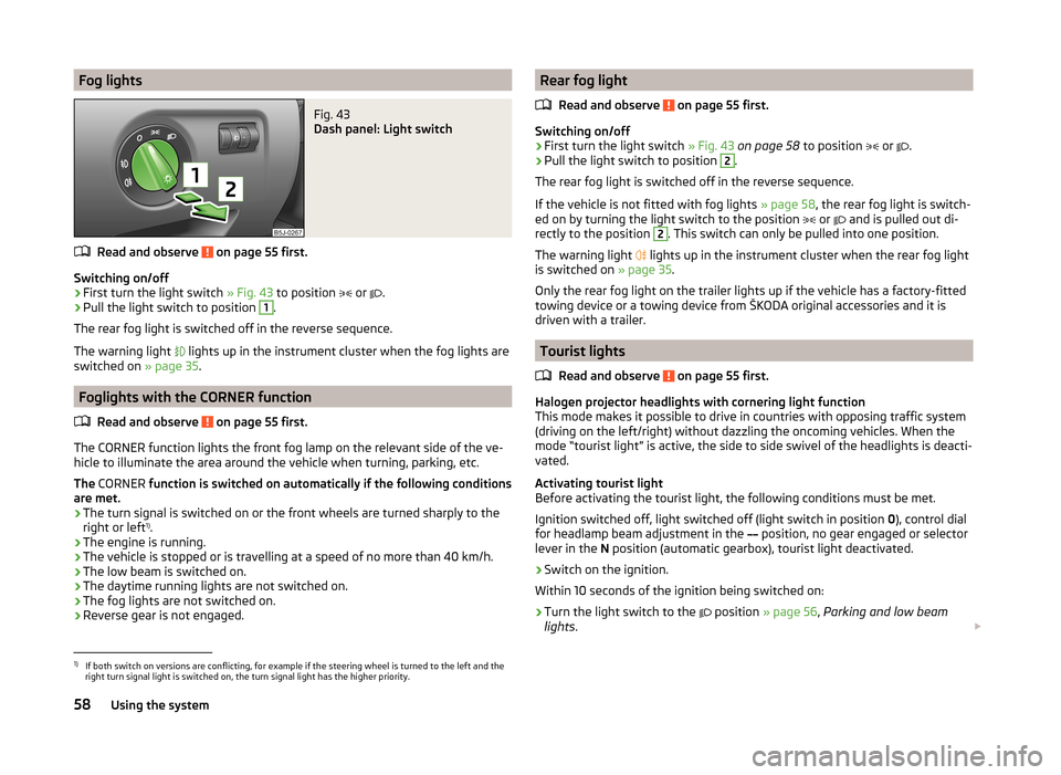
Fog lightsFig. 43
Dash panel: Light switch
Read and observe on page 55 first.
Switching on/off
›
First turn the light switch » Fig. 43 to position
or
.
›
Pull the light switch to position
1
.
The rear fog light is switched off in the reverse sequence.
The warning light lights up in the instrument cluster when the fog lights are
switched on » page 35.
Foglights with the CORNER function
Read and observe
on page 55 first.
The CORNER function lights the front fog lamp on the relevant side of the ve-
hicle to illuminate the area around the vehicle when turning, parking, etc.
The CORNER function is switched on automatically if the following conditions
are met.
› The turn signal is switched on or the front wheels are turned sharply to the
right or left 1)
.
› The engine is running.
› The vehicle is stopped or is travelling at a speed of no more than 40 km/h.
› The low beam is switched on.
› The daytime running lights are not switched on.
› The fog lights are not switched on.
› Reverse gear is not engaged.
Rear fog light
Read and observe
on page 55 first.
Switching on/off
›
First turn the light switch » Fig. 43 on page 58 to position
or
.
›
Pull the light switch to position
2
.
The rear fog light is switched off in the reverse sequence.
If the vehicle is not fitted with fog lights » page 58, the rear fog light is switch-
ed on by turning the light switch to the position
or
and is pulled out di-
rectly to the position
2
. This switch can only be pulled into one position.
The warning light lights up in the instrument cluster when the rear fog light
is switched on » page 35.
Only the rear fog light on the trailer lights up if the vehicle has a factory-fitted
towing device or a towing device from ŠKODA original accessories and it is
driven with a trailer.
Tourist lights
Read and observe
on page 55 first.
Halogen projector headlights with cornering light function
This mode makes it possible to drive in countries with opposing traffic system
(driving on the left/right) without dazzling the oncoming vehicles. When the
mode “tourist light” is active, the side to side swivel of the headlights is deacti-
vated.
Activating tourist light
Before activating the tourist light, the following conditions must be met.
Ignition switched off, light switched off (light switch in position 0), control dial
for headlamp beam adjustment in the position, no gear engaged or selector
lever in the N position (automatic gearbox), tourist light deactivated.
›
Switch on the ignition.
Within 10 seconds of the ignition being switched on:
›
Turn the light switch to the position
» page 56 , Parking and low beam
lights .
1)
If both switch on versions are conflicting, for example if the steering wheel is turned to the left and the
right turn signal light is switched on, the turn signal light has the higher priority.
58Using the system
Page 118 of 197
Parking aid
Introduction
This chapter contains information on the following subjects:
Function
116
Activation/deactivation
116WARNING■ The parking aid is not a substitute for the driver paying proper attention
and it is always the driver's responsibility to take care when reversing the
vehicle or carrying out similar manoeuvres. Pay particular attention to small
children and animals as they are not recognised by the parking aid sensors.■
Before reversing, you should make sure that there are no small obstacles,
such as rocks, thin posts, trailer drawbars etc. behind your vehicle. Such ob-
stacles may not be recognised by the parking aid sensors.
■
Under certain circumstances, surfaces of certain objects and types of
clothing cannot reflect the system signals. Thus, these objects or people
who wear such clothing are not recognised by the System sensors.
■
External sound sources can have a detrimental effect on the system. Un-
der adverse conditions, this may cause objects or people to not be recog-
nised by the system.
CAUTION
■ If a warning signal sounds for about 3 seconds after activating the system
and there is no obstacle close to your car, this indicates a system fault. Have
the fault rectified by a specialist garage.■
The sensors must be kept clean (free of ice, etc.) to enable the parking aid to
operate properly.
■
Under adverse weather conditions (heavy rain, water vapour, very low or
high temperatures etc.) system function may be limited.
■
Additionally fitted modules, such as a bicycle rack, can impair the function of
the parking aid.
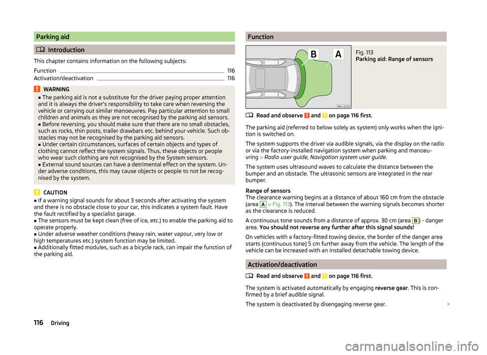
FunctionFig. 113
Parking aid: Range of sensors
Read and observe and on page 116 first.
The parking aid (referred to below solely as system) only works when the igni-
tion is switched on.
The system supports the driver via audible signals, via the display on the radio
or via the factory-installed navigation system when parking and manoeu-
vring » Radio user guide, Navigation system user guide.
The system uses ultrasound waves to calculate the distance between the
bumper and an obstacle. The ultrasonic sensors are integrated in the rear
bumper.
Range of sensors
The clearance warning begins at a distance of about 160 cm from the obstacle
(area
A
» Fig. 113 ). The interval between the warning signals becomes shorter
as the clearance is reduced.
A continuous tone sounds from a distance of approx. 30 cm (area
B
) - danger
area. You should not reverse any further after this signal sounds!
On vehicles with a factory-fitted towing device, the border of the danger area
starts (continuous tone) 5 cm further away from the vehicle. The length of the
vehicle can be increased with an installed detachable towing device.
Activation/deactivation
Read and observe
and on page 116 first.
The system is activated automatically by engaging reverse gear. This is con-
firmed by a brief audible signal.
The system is deactivated by disengaging reverse gear.
116Driving
Page 119 of 197
NoteThe system cannot be activated on vehicles with a factory-fitted towing device
when towing a trailer.
Cruise control system
Introduction
This chapter contains information on the following subjects:
Storing a speed
117
Changing a stored speed
117
Switching off temporarily
118
Switching off completely
118
The cruise control system (CCS) maintains a constant speed above 25 km/h,
once it has been set, without you having to depress the accelerator pedal.
This is only possible within the range which is permitted by the power output
and braking power of the engine.
The warning light in the instrument cluster lights up when the cruise con-
trol system is switched on.
WARNING■ For safety reasons, the cruise control system must not be used in dense
traffic or on unfavourable road surfaces (such as icy roads, slippery roads,
loose gravel) – there is a risk of an accident.■
The saved speed may only be resumed if it is not too high for the current
traffic conditions.
■
Always deactivate the cruise control system after use to prevent the sys-
tem being enabled unintentionally.
CAUTION
■ The cruise control system is not able to maintain a constant speed when
driving in areas with steeper gradients. The weight of the vehicle increases the
speed at which it travels. Therefore, shift to a lower gear in good time or slow
the vehicle down by applying the foot brake.■
It is not possible to switch on the cruise control system on vehicles fitted
with a manual gearbox if first gear or reverse gear is engaged.
■ It is not possible on vehicles fitted with an automatic gearbox to switch on
the cruise control system if the selector lever is in the position P, N or R.■
The cruise control system may automatically switch off when some brake as-
sist systems (e.g. ESC) intervene, when the speed exceeds maximum permissi-
ble engine speed, or a similar event takes place.
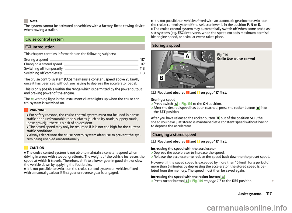
Storing a speed
Fig. 114
Stalk: Use cruise control
Read and observe and on page 117 first.
Storing a speed
›
Press switch
A
» Fig. 114 to the ON position.
›
After the desired speed has been reached, press the rocker button
B
into
the SET position.
After you have released the rocker button
B
out of the position SET, the
speed you have just stored is maintained at a constant speed without having
to depress the accelerator.
Changing a stored speed
Read and observe
and on page 117 first.
Increasing the speed with the accelerator
›
Depress the accelerator to increase the speed.
›
Release the accelerator to reduce the speed back down to the preset speed.
However, if the saved speed is exceeded by more than 10 km/h for a period of more than 5 minutes by depressing the accelerator, the stored speed is de-
leted from the memory. The speed must then be saved again.
Increasing the speed with the rocker button
B›
Press rocker button
B
» Fig. 114 on page 117 to the RES position.
117Assist systems
Page 122 of 197
Error: start-stop system
ERROR START-STOP
A system error is present. Seek help from a specialist garage.Towing a trailer
Towing device
Introduction
This chapter contains information on the following subjects:
Description
121
Adjusting the ready position
121
Fitting the ball head
122
Check proper fitting
122
Removing the ball head
123
Use and care
123
If your vehicle has already been factory-fitted with towing equipment or is fit-
ted with towing equipment from ŠKODA Original Accessories, then it meets all
of the technical requirements and national legal provisions for towing a trailer.
Your vehicle is fitted with a 13-pin power socket for the electrical connection
between the vehicle and trailer. If the trailer that is to be towed has a 7-pin
connector , you can use a suitable adapter from ŠKODA Original Accessories.
The maximum trailer drawbar load is 50 kg.
WARNING■
Check that the ball head is seated correctly and is secured in the mount-
ing recess before starting any journey.■
Do not use the ball head if it is not correctly inserted in the mounting re-
cess.
■
Do not use the towing equipment if it is damaged or incomplete.
■
Do not modify or adapt the towing equipment in any way.
■
Never release the ball head while the trailer is still coupled.
CAUTION
Take care with the ball head to avoid damaging the paintwork on the bumper.120Driving
Page 123 of 197
DescriptionFig. 117
Remove cover cap: on the rear bumper / for the receiving shaft
Fig. 118
Ball head
Read and observe and on page 120 first.
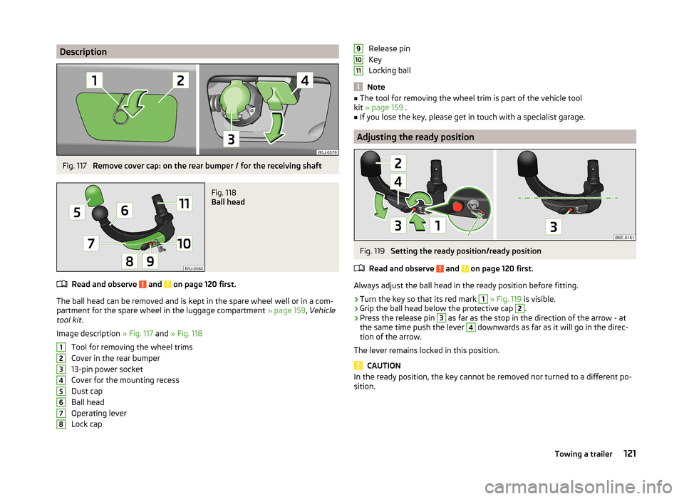
The ball head can be removed and is kept in the spare wheel well or in a com-
partment for the spare wheel in the luggage compartment » page 159, Vehicle
tool kit .
Image description » Fig. 117 and » Fig. 118
Tool for removing the wheel trims
Cover in the rear bumper
13-pin power socket
Cover for the mounting recess
Dust cap
Ball head
Operating lever
Lock cap
12345678Release pin
Key
Locking ball
Note
■ The tool for removing the wheel trim is part of the vehicle tool
kit » page 159 .■
If you lose the key, please get in touch with a specialist garage.
Adjusting the ready position
Fig. 119
Setting the ready position/ready position
Read and observe
and on page 120 first.
Always adjust the ball head in the ready position before fitting.
›
Turn the key so that its red mark
1
» Fig. 119 is visible.
›
Grip the ball head below the protective cap
2
.
›
Press the release pin
3
as far as the stop in the direction of the arrow - at
the same time push the lever
4
downwards as far as it will go in the direc-
tion of the arrow.
The lever remains locked in this position.
CAUTION
In the ready position, the key cannot be removed nor turned to a different po-
sition.91011121Towing a trailer