brake light SKODA FABIA 2014 3.G / NJ Operating Instruction Manual
[x] Cancel search | Manufacturer: SKODA, Model Year: 2014, Model line: FABIA, Model: SKODA FABIA 2014 3.G / NJPages: 216, PDF Size: 30.9 MB
Page 118 of 216
Downloaded from www.Manualslib.com manuals search engine During an intervention of the system, the warning light flashes in the instru-
ment cluster.
Anti-lock braking system (ABS)
Read and observe
on page 114 first.
ABS prevents the wheels locking when braking. Thereby, it helps the driver to
maintain control of the vehicle.
The intervention of the ABS is noticeable from the pulsating movements of
the brake pedal which is accompanied by noises.
When the ABS system is active, do not pump the brakes or lift off the brake
pedal.
Traction control (TCS)
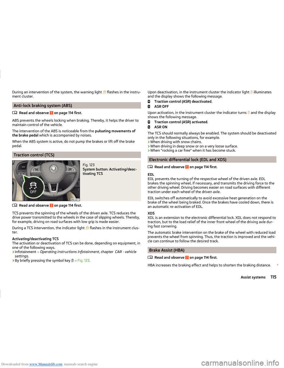
Fig. 123
System button: Activating/deac-
tivating TCS
Read and observe on page 114 first.
TCS prevents the spinning of the wheels of the driven axle. TCS reduces the drive power transmitted to the wheels in the case of slipping wheels. Thereby,
for example, driving on road surfaces with low grip is made easier.
During a TCS intervention, the indicator light flashes in the instrument clus-
ter.
Activating/deactivating TCS
The activation or deactivation of TCS can be done, depending on equipment, in
one of the following ways.
› Infotainment
» Operating instructions Infotainment , chapter CAR - vehicle
settings .
› By briefly pressing the symbol key
» Fig. 123 .
Upon deactivation, in the instrument cluster the indicator light illuminates
and the display shows the following message.
Traction control (ASR) deactivated.
ASR OFF
Upon activation, in the instrument cluster the indicator turns
and the display
shows the following message.
Traction control (ASR) activated.
ASR ON
The TCS should normally always be enabled. The system should be deactivated
only in the following situations, for example.
› When driving with snow chains.
› When driving in deep snow or on a very loose surface.
› When “rocking a car free” when it has become stuck.
Electronic differential lock (EDL and XDS)
Read and observe
on page 114 first.
EDL
EDL prevents the turning of the respective wheel of the driven axle. EDL
brakes the spinning wheel, if necessary, and transmits the driving force to the
other driving wheel. Driving becomes easier on road surfaces with different
traction under each wheel of the driven axle.
EDL switches off automatically to avoid excessive heat generation on the
brake of the wheel being braked. Once the brakes have cooled down, there is
an automatic re-activation of EDL.
XDS
XDL is an extension to the electronic differential lock. XDL does not respond to
traction, but to the load relief of the inner front wheel of the driving axle dur-
ing fast cornering.
The automatic brake intervention on the brake of the wheel with reduced load
prevents the wheel from spinning. Thus, the traction is improved and the vehi-
cle can continue to follow the desired track.
Brake Assist (HBA)
Read and observe
on page 114 first.
HBA increases the braking effect and helps to shorten the braking distance.
115Assist systems
Page 123 of 216

Downloaded from www.Manualslib.com manuals search engine Activate CCS (control deactivated)BTake control againa)
/ Increase speedCStart control / reduce speedDSwitch between GRA and Speed Limiter » page 120a)
If no speed is set the current speed is adopted.
At the start of the regulation the GRA regulates the vehicle to the current
speed, and this speed is shown on the instrument cluster display. The warning
light
illuminates in the instrument cluster.
Automatic control interruption
Automatic control interruption occurs if any of the following conditions are
met.
› The brake pedal is operated.
› When one of the brake assist systems (e.g. ESC) intervenes.
› Through an airbag deployment.
› The key
is actuated.
WARNING■
Always deactivate the cruise control system after use to prevent the sys-
tem being enabled unintentionally.■
Control may only be resumed if the set speed is not too high for the cur-
rent traffic conditions.
Note
■ During control, speed can be increased by pressing the accelerator pedal. Re-
leasing the accelerator pedal will cause the speed to drop again to the set
speed.■
By pressing the
button during the regulation this is cancelled and the
Speed Limiter is activated.
Speed limiter
Introduction
This chapter contains information on the following subjects:
Operation
120
Operation description
121
The Speed Limiter limits the maximum driving speed to the set speed limit.
This limit can only be exceeded by depressing the accelerator pedal fully.
The condition in which the Speed Limiter monitors a potential set speed limit
excess is referred to as Regulation.WARNING■
The speed limiter only serves as an assistance and does not relieve the
driver of the responsibility for the vehicle operation.■
Always adjust the speed and driving style to the current visibility, weath-
er, road and traffic conditions.
Operation
Fig. 132
Maxi DOT display: Examples of Speed Limiter status displays
120Driving
Page 125 of 216
Downloaded from www.Manualslib.com manuals search engine Front Assistant
Introduction
This chapter contains information on the following subjects:
Radar sensor
122
Operation
123
Distance warning (dangerous distance)
123
Warning and automatic braking
123
Disable / enable
124
Information messages
124
The Front Assistant (from here on only referred to as the system) warns you of
the danger of a collision with a vehicle or another obstacle in front of the vehi-
cle and tries to avoid a collision or mitigate its consequences by automatically
applying the brakes as appropriate.
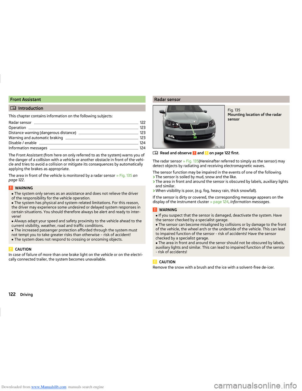
The area in front of the vehicle is monitored by a radar sensor » Fig. 135 on
page 122 .
WARNING■
The system only serves as an assistance and does not relieve the driver
of the responsibility for the vehicle operation.■
The system has physical and system-related limitations. For this reason,
the driver may experience some undesired or delayed system responses in
certain situations. You should therefore always be alert and ready to inter-
vene!
■
Always adapt your speed and safety proximity to the vehicle ahead to the
current visibility, weather, road and traffic conditions.
■
The increased passenger protection afforded through the system must
not tempt you to take greater risks than otherwise – risk of accident!
■
The system does not respond to crossing or oncoming objects.
CAUTION
In case of failure of more than one brake light on the vehicle or on the electri-
cally connected trailer, the system becomes unavailable.Radar sensorFig. 135
Mounting location of the radar
sensor
Read and observe and on page 122 first.
The radar sensor » Fig. 135(Hereinafter referred to simply as the sensor) may
detect objects by radiating and receiving electromagnetic waves.
The sensor function may be impaired in the events of one of the following.
› The sensor is soiled by mud, snow and the like.
› The area in front and around the sensor is obscured by labels, auxiliary lights
and similar.
› When visibility is poor, (e.g. fog, heavy rain, thick snowfall).
If the sensor is dirty or covered, the corresponding message appears on the
display of the instrument cluster » page 124, Information messages .
WARNING■
If you suspect that the sensor is damaged, deactivate the system. Have
the sensor checked by a specialist garage.■
The sensor can become misaligned by collisions or by damage to the front
of the vehicle, the wheel arch or the underside of the vehicle. This can lead
to impaired function of the sensor - risk of accidents! Have the sensor
checked by a specialist garage.
■
The area in front and around the senor should not be obscured by labels,
auxiliary lights and similar. This can lead to impaired function of the sensor
- risk of accidents!
CAUTION
Remove the snow with a brush and the ice with a solvent-free de-icer.122Driving
Page 136 of 216
Downloaded from www.Manualslib.com manuals search engine Trailer, connect and disconnectFig. 153
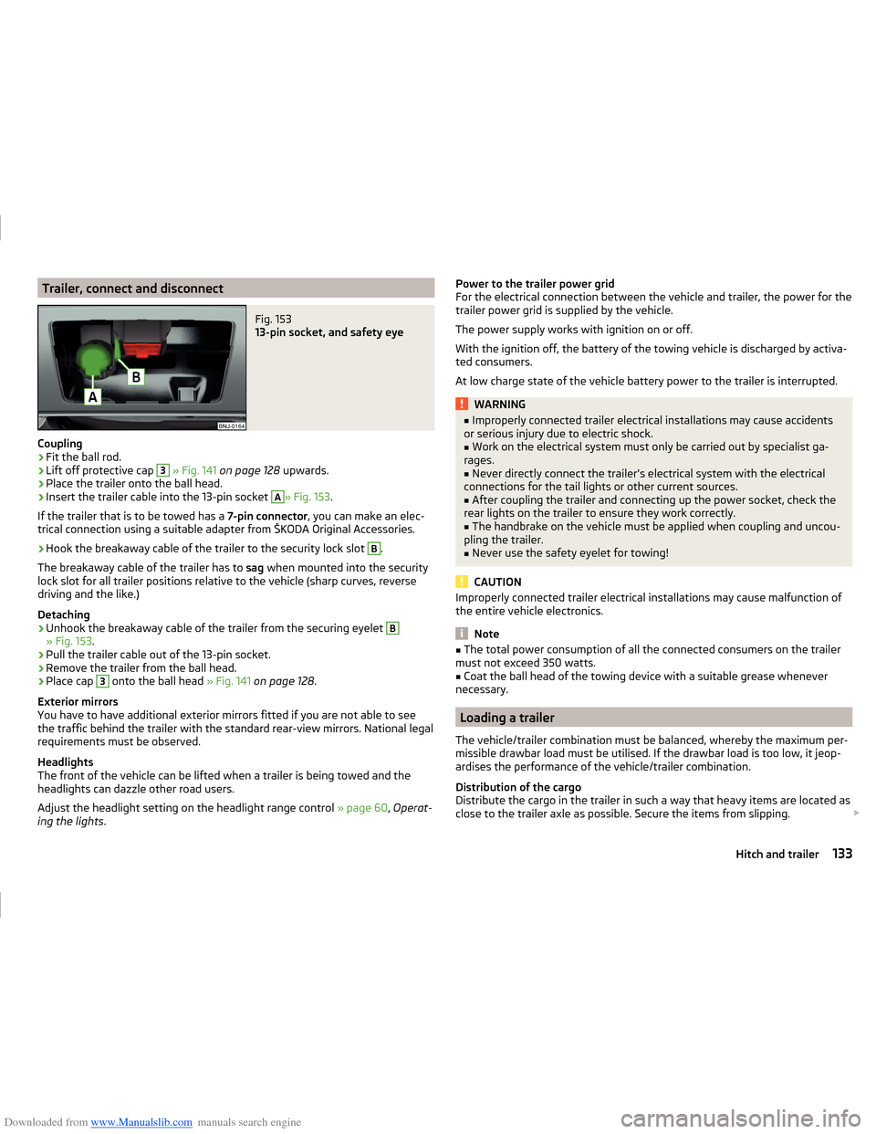
13-pin socket, and safety eye
Coupling
›
Fit the ball rod.
›
Lift off protective cap
3
» Fig. 141 on page 128 upwards.
›
Place the trailer onto the ball head.
›
Insert the trailer cable into the 13-pin socket
A
» Fig. 153.
If the trailer that is to be towed has a 7-pin connector, you can make an elec-
trical connection using a suitable adapter from ŠKODA Original Accessories.
›
Hook the breakaway cable of the trailer to the security lock slot
B
.
The breakaway cable of the trailer has to sag when mounted into the security
lock slot for all trailer positions relative to the vehicle (sharp curves, reverse
driving and the like.)
Detaching
›
Unhook the breakaway cable of the trailer from the securing eyelet
B
» Fig. 153 .
›
Pull the trailer cable out of the 13-pin socket.
›
Remove the trailer from the ball head.
›
Place cap
3
onto the ball head » Fig. 141 on page 128 .
Exterior mirrors
You have to have additional exterior mirrors fitted if you are not able to see
the traffic behind the trailer with the standard rear-view mirrors. National legal
requirements must be observed.
Headlights
The front of the vehicle can be lifted when a trailer is being towed and the
headlights can dazzle other road users.
Adjust the headlight setting on the headlight range control » page 60, Operat-
ing the lights .
Power to the trailer power grid
For the electrical connection between the vehicle and trailer, the power for the
trailer power grid is supplied by the vehicle.
The power supply works with ignition on or off.
With the ignition off, the battery of the towing vehicle is discharged by activa-
ted consumers.
At low charge state of the vehicle battery power to the trailer is interrupted.WARNING■ Improperly connected trailer electrical installations may cause accidents
or serious injury due to electric shock.■
Work on the electrical system must only be carried out by specialist ga-
rages.
■
Never directly connect the trailer's electrical system with the electrical
connections for the tail lights or other current sources.
■
After coupling the trailer and connecting up the power socket, check the
rear lights on the trailer to ensure they work correctly.
■
The handbrake on the vehicle must be applied when coupling and uncou-
pling the trailer.
■
Never use the safety eyelet for towing!
CAUTION
Improperly connected trailer electrical installations may cause malfunction of
the entire vehicle electronics.
Note
■ The total power consumption of all the connected consumers on the trailer
must not exceed 350 watts.■
Coat the ball head of the towing device with a suitable grease whenever
necessary.
Loading a trailer
The vehicle/trailer combination must be balanced, whereby the maximum per-
missible drawbar load must be utilised. If the drawbar load is too low, it jeop-
ardises the performance of the vehicle/trailer combination.
Distribution of the cargo
Distribute the cargo in the trailer in such a way that heavy items are located as
close to the trailer axle as possible. Secure the items from slipping.
133Hitch and trailer
Page 137 of 216
Downloaded from www.Manualslib.com manuals search engine The distribution of the weight is very poor if your vehicle is unladen and the
trailer is laden. Maintain a particularly low speed if you cannot avoid driving
with this combination.
Tyre pressure
Correct the tyre inflation pressure on your vehicle for a “full load” » page 161.
Towing capacity and trailer weight
The permissible trailer load must not be exceeded under any circumstances
» page 192 , Technical data .
The details given in the vehicle's technical documentation always take prece-
dence over the details in the Owner's Manual.
The trailer loads specified apply only to altitudes up to 1,000 metres above
mean sea level.
The engine output falls as altitude increases, as does the ability to climb.
Therefore, for every additional 1,000 m in height (or part), the maximum per-
missible towed weight must be reduced by 10 %.
The towed weight comprises the actual weights of the (loaded) towing vehicle and the (loaded) trailer.
The trailer and drawbar load information on the type plate of the towing
equipment are merely test data for the towing equipment. The vehicle-specific
values are detailed in the vehicle documents.WARNING■ Do not exceed the maximum permissible axle and drawbar load and
weight of the trailer - risk of accident and serious injuries!■
An unsecured load can adversely affect stability and driving safety signifi-
cantly - there is a risk of accident!
Towing a trailer
Driving speed
For safety reasons, do not drive faster than 80 km/h when towing a trailer.
Immediately reduce your speed as soon as even the slightest swaying of the
trailer is detected. Never attempt to stop the trailer from “swaying” by acceler-
ating.
Brakes
Apply the brakes in good time! If the trailer is fitted with a trailer brake, apply
the brakes gently at first, then brake firmly. This will avoid brake jolts resulting
from the trailer wheels locking.
On downhill sections shift down a gear in good time to also use the engine as
a brake.
Engine overheating
If the pointer of the coolant temperature gauge reaches the red scale range,
the speed should be reduced immediately.
Stop and switch off the engine if the warning light
illuminates in the instru-
ment cluster display.
The following information must be observed » page 36,
Coolant
.
The coolant temperature can be reduced by switching on the heating.WARNING■ Always drive particularly carefully with the trailer.■Adapt your speed to the conditions of the road surface and to the traffic
situation.
CAUTION
If you tow a trailer frequently, you should also have your vehicle inspected be-
tween service intervals.
Anti-theft alarm system
When the vehicle is locked, the alarm is activated when the electrical connec-
tion to the trailer is interrupted.
Always switch off the anti-theft alarm system before a trailer is coupled or un-
coupled » page 54 .
Conditions for including a trailer in the anti-theft alarm system. The vehicle is factory-fitted with an anti-theft alarm system and towing
equipment.
The trailer is electrically connected to the towing vehicle by means of the
trailer socket.
The electrical system of the vehicle and trailer is functional.
The vehicle is locked with the vehicle key and the anti-theft alarm system
is activated.
134Driving
Page 146 of 216
Downloaded from www.Manualslib.com manuals search engine CAUTIONInformation for cleaning windows■Do not clean the inside of the windows with sharp-edged objects or corro-
sive and acidic cleaning agents – there is a risk of damaging the heating ele-
ments or window aerial.■
When drying the windows after washing the vehicle, do not use window
leathers that have been used to polish the bodywork. Residues of preserva-
tives in the chamois leather can smear the windows and reduce visibility.
Headlight glasses
Read and observe
and on page 141 first.
Clean the plastic headlight lenses with clean, warm water and soap.
CAUTION
■The headlights are never to be wiped dry - there is a risk of damaging the
protective lacquer and the headlight glass subsequently developing cracks.■
Do not use sharp objects to clean the glasses - there is a risk of damaging
the protective lacquer and the headlight glasses subsequently developing
cracks.
■
Do not use any aggressive cleaning or chemical solvent products to clean the
headlights – risk of damaging the headlight lenses.
Door closing cylinder
Read and observe
and on page 141 first.
Specific products must be used for de-icing door lock cylinders.
CAUTION
Make sure that as little water as possible gets into the locking cylinder when
washing the vehicle - there is a risk of freezing the lock cylinder!
Cavity protection
Read and observe
and on page 141 first.
All the cavities of your vehicle which are at risk from corrosion are protectedfor life by a layer of protective wax applied in the factory.
Wax protection does not require to be inspected or re-treated.
If any small amount of wax flow out of the cavities at high temperatures, these
must be removed with a plastic scraper and the stains cleaned using a petrole-
um cleaner.WARNINGSafety regulations should be observed when using petroleum cleaner to re-
move wax – there is a risk of fire.
Jack
Read and observe
and on page 141 first.
The jack is maintenance-free.
If necessary, the moving parts of the jack should be lubricated with a suitable lubricant.
Wheels
Read and observe
and on page 141 first.
Wheel rims
Also thoroughly wash the wheel rims when washing the vehicle on a regular basis.
Regularly remove salt and brake dust otherwise the rim material will be at-
tacked.
Light alloy wheels
After washing thoroughly and treat the wheel rims with a protective product
for light alloy wheels.
For the treatment of wheel rims do not use products which may cause damage
to the paint on the rims.
CAUTION
■ Damage to the paint layer on the wheel rims must be touched up immediate-
ly.■
Severe layers of dirt on the wheels can also result in wheel imbalance. This
may show itself in the form of a wheel vibration which is transmitted to the
steering wheel which, in certain circumstances, can cause premature wear of
the steering. This means it is necessary to remove the dirt.
143Care and maintenance
Page 158 of 216
Downloaded from www.Manualslib.com manuals search engine ■Additional headlights and other attached components in front of the air inlet
impair the cooling efficiency of the coolant.■
Never cover the radiator - there is a risk of the engine overheating.
Checking the coolant level
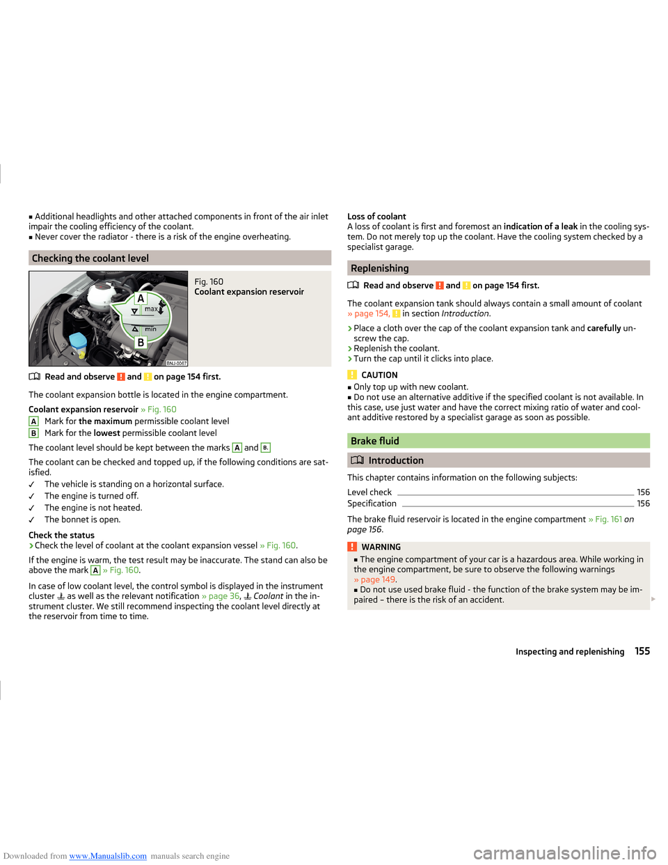
Fig. 160
Coolant expansion reservoir
Read and observe and on page 154 first.
The coolant expansion bottle is located in the engine compartment.
Coolant expansion reservoir » Fig. 160
Mark for the maximum permissible coolant level
Mark for the lowest permissible coolant level
The coolant level should be kept between the marks
A
and
B.
The coolant can be checked and topped up, if the following conditions are sat-
isfied.
The vehicle is standing on a horizontal surface.
The engine is turned off.
The engine is not heated.
The bonnet is open.
Check the status
›
Check the level of coolant at the coolant expansion vessel » Fig. 160.
If the engine is warm, the test result may be inaccurate. The stand can also be
above the mark
A
» Fig. 160 .
In case of low coolant level, the control symbol is displayed in the instrument
cluster as well as the relevant notification
» page 36,
Coolant
in the in-
strument cluster. We still recommend inspecting the coolant level directly at
the reservoir from time to time.
ABLoss of coolant
A loss of coolant is first and foremost an indication of a leak in the cooling sys-
tem. Do not merely top up the coolant. Have the cooling system checked by a
specialist garage.
Replenishing
Read and observe
and on page 154 first.
The coolant expansion tank should always contain a small amount of coolant» page 154, in section Introduction .
›
Place a cloth over the cap of the coolant expansion tank and carefully un-
screw the cap.
›
Replenish the coolant.
›
Turn the cap until it clicks into place.
CAUTION
■ Only top up with new coolant.■Do not use an alternative additive if the specified coolant is not available. In
this case, use just water and have the correct mixing ratio of water and cool-
ant additive restored by a specialist garage as soon as possible.
Brake fluid
Introduction
This chapter contains information on the following subjects:
Level check
156
Specification
156
The brake fluid reservoir is located in the engine compartment » Fig. 161 on
page 156 .
WARNING■
The engine compartment of your car is a hazardous area. While working in
the engine compartment, be sure to observe the following warnings
» page 149 .■
Do not use used brake fluid - the function of the brake system may be im-
paired – there is the risk of an accident.
155Inspecting and replenishing
Page 159 of 216
Downloaded from www.Manualslib.com manuals search engine CAUTION■Do not continue your journey if the fluid level has dropped below the “MIN”
marking » Fig. 161 on page 156 , - there is a risk of an accident! Seek help
from a specialist garage.■
Brake fluid damages the paintwork of the vehicle.
Note
■ The brake fluid is changed as part of a prescribed inspection service.■We recommend using oils from the ŠKODA Original Accessories range.
Level check
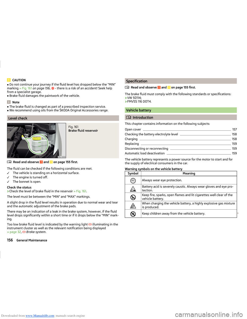
Fig. 161
Brake fluid reservoir
Read and observe and on page 155 first.
The fluid can be checked if the following conditions are met.
The vehicle is standing on a horizontal surface.
The engine is turned off.
The bonnet is open.
Check the status
›
Check the level of brake fluid in the reservoir » Fig. 161.
The level must be between the “MIN” and “MAX” markings.
A slight drop in the fluid level results in operation due to normal wear and tear
and the automatic adjustment of the brake pads.
There may be an indication of a leak in the brake system, however, if the fluid level drops significantly within a short time or if it drops below the “MIN” mark-
ing.
Too low brake fluid level is indicated by the warning light
illuminating in the
instrument cluster as well as the relevant notification being displayed
» page 32 ,
Brake system .
Specification
Read and observe
and on page 155 first.
The brake fluid must comply with the following standards or specifications:› VW 50114;
› FMVSS 116 DOT4.
Vehicle battery
Introduction
This chapter contains information on the following subjects:
Open cover
157
Checking the battery electrolyte level
158
Charging
158
Replacing
159
Disconnecting or reconnecting
159
Automatic load deactivation
159
The vehicle battery represents a power source for the motor to start and for
the supply of electrical consumers in the car.
Warning symbols on the vehicle battery
SymbolMeaningAlways wear eye protection.Battery acid is severely caustic. Always wear gloves and eye pro-
tection.Keep fire, sparks, open flames and lit cigarettes well clear of the
vehicle battery.When charging the vehicle battery, a highly explosive gas mixture
is produced.Keep children away from the vehicle battery. 156General Maintenance
Page 171 of 216
Downloaded from www.Manualslib.com manuals search engine CAUTION■Screw the jack back to the starting position before storing in the box with
the tool kit screws.■
Ensure that the vehicle tool kit is safely secured in the boot.
■
Ensure that the box is always secured with the strap.
Note
The declaration of conformity is included with the jack or the log folder.
Changing a wheel
Introduction
This chapter contains information on the following subjects:
Preparation
168
Remove / store wheel
168
Full wheel trim
168
Wheel bolts
169
Anti-theft wheel bolts
169
Loosening/tightening wheel bolts
170
Raising the vehicle
170
Remove the wheel / fix
171
Subsequent steps
171
For your own safety and the safety of the passengers, the following instruc-
tions must be observed before changing a wheel on the road.
Switch on the hazard lights.
The warning triangle must be set up at the prescribed distance - observe
the national legal provisions when doing so.
Park the vehicle as far away as possible from the flow of traffic.
Choose a location with a flat, solid surface.
Have all the occupants get out. The passengers should not stand on the
road (instead they should remain behind a crash barrier, for instance) while
the wheel is being changed.
The national legal requirements must be observed when changing a wheel.
Preparation
Before changing the wheel, the following work should be carried out.
› Switch off the engine.›Select the
first gear or move the selector lever for the automatic gearbox
into position P .›
Apply the handbrake firmly.
›
Uncouple trailer, if attached.
›
Remove the vehicle tool kit » page 167 and the spare wheel from the boot.
Remove / store wheel
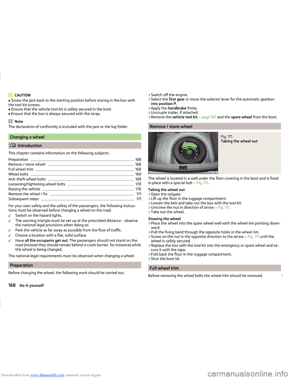
Fig. 171
Taking the wheel out
The wheel is located in a well under the floor covering in the boot and is fixed
in place with a special bolt » Fig. 171.
Taking the wheel out
›
Open the tailgate.
›
Lift up the floor in the luggage compartment.
›
Loosen the belt and take out the box with the tool kit.
›
Unscrew the nut in direction of arrow » Fig. 171.
›
Take out the wheel.
Stowing the wheel
›
Place the wheel into the spare wheel well with the wheel rim pointing down-
ward.
›
Pull the fixing band through the opposite holes in the wheel rim.
›
Screw on the nut in the opposite direction to the arrow » Fig. 171 until the
wheel is safely secured.
›
Replace the box with the tool kit into the emergency or spare wheel and se-
cure it with the tape.
›
Fold back the floor in the luggage compartment.
›
Shut the boot lid.
Full wheel trim
Before removing the wheel bolts the wheel trim should be removed.
168Do-it-yourself
Page 176 of 216
Downloaded from www.Manualslib.com manuals search engine General informationRead and observe
on page 172 first.
For your own safety and the safety of your passengers, the following instruc-
tions must be observed before carrying out a wheel repair on the road.
Switch on the hazard lights.
The warning triangle must be set up at the prescribed distance - observe
the national legal provisions when doing so.
Park the vehicle as far away as possible from the flow of traffic.
Choose a location with a flat, solid surface.
Have all the occupants get out. The passengers should not stand on the
road (instead they should remain behind a crash barrier, for instance) while
the wheel is being changed.
The national legal requirements must be observed when repairing a tyre.
The breakdown kit must not be used under the following circumstances. › The rim is damaged.
› The outside temperature is below -20 ° C.
› The cut or puncture is larger than 4 mm.
› The tyre wall is damaged.
› After the expiration date (see inflation bottle).
Preparations for using the breakdown kit
Read and observe
on page 172 first.
The following preparatory work must be carried out before using the break-
down kit.
›
Switch off the engine.
›
Select the first gear or move the selector lever for the automatic gearbox
into position P .
›
Apply the handbrake firmly.
›
Check that you can carry out the repairs with the breakdown kit » page 173,
General information .
›
Uncouple trailer, if attached.
›
Remove the breakdown kit from the boot.
›
Stick the corresponding sticker
1
» Fig. 177 on page 172 on the dashboard in
the driver's field of view.
›
Unscrew the valve cap.
› Use the valve remover 2 to unscrew the valve core and place it on a clean
surface (rag, paper, etc.).
Sealing and inflating the tyre
Read and observe
on page 172 first.
Sealing
›
Shake the tyre inflator bottle
10
» Fig. 177 on page 172 vigorously several
times.
›
Firmly screw the inflation hose
3
onto the tyre inflator bottle
10
in a clock-
wise direction. The film on the cap is pierced automatically.
›
Remove the plug from the inflation hose
3
and push the open end fully on-
to the tyre valve.
›
Hold the bottle
10
with the bottom facing upwards and fill all of the sealing
agent from the tyre inflator bottle into the tyre.
›
Remove the filler plug from the tyre valve.
›
Screw the valve core back into the tyre valve using the valve remover
2
.
Inflating
›
Screw the air compressor tyre inflation hose
7
» Fig. 177 on page 172 firmly
onto the tyre valve.
›
For vehicles with Manual transmission move the lever into the neutral posi-
tion and apply the parking brake firmly.
›
For vehicles with Automatic transmission move the selector lever to position
P and apply the parking brake firmly.
›
Start the engine and run it in idle.
›
Plug the connector
6
into 12 volt socket » page 78.
›
Switch on the air compressor with the ON and OFF switch
9
.
›
Allow the air compressor to run until a pressure of 2.0 - 2.5 bar is achieved.
Maximum run time of 8 minutes » .
›
Switch off the air compressor.
›
If you cannot reach an air pressure of 2.0 – 2.5 bar, unscrew the tyre inflation
hose
7
from the tyre valve.
›
Drive the vehicle 10 metres forwards or backwards to allow the sealing agent
to “distribute” in the tyre.
›
Firmly screw the tyre inflation hose
7
back onto the tyre valve and repeat
the inflation process.
›
If you still cannot reach the required tyre inflation pressure, this means the
tyre has sustained too much damage. You cannot seal with tyre with the
breakdown kit »
.
›
Switch off the air compressor.
173Emergency equipment, and self-help