service SKODA FABIA 2014 3.G / NJ Operating Instruction Manual
[x] Cancel search | Manufacturer: SKODA, Model Year: 2014, Model line: FABIA, Model: SKODA FABIA 2014 3.G / NJPages: 216, PDF Size: 30.9 MB
Page 156 of 216
Downloaded from www.Manualslib.com manuals search engine WARNINGThe engine compartment of your car is a hazardous area. While working in
the engine compartment, be sure to observe the following warnings
» page 149 .
CAUTION
Do not pour any additives into the engine oil – risk of serious damage to the
engine parts.
Note
■ Before a long drive we recommend that you purchase and carry with you en-
gine oil which complies with the specification for your vehicle.■
We recommend that you use oils from ŠKODA Original Accessories.
■
You must wash yourself thoroughly if your skin has come into contact with
oil.
Specification
Read and observe
and on page 153 first.
Vehicles with variable service intervals
Petrol enginesSpecification1.0 l/44, 55 kW MPI - EU6VW 504 001.2 l/66, 81 kW TSIDiesel engineSpecification1.4 l/66, 77 kW TDI CRVW 507 00
Vehicles with fixed service intervals
Petrol enginesSpecification1.0 l/44, 55 kW MPI - EU6
VW 502 00
1.0 l/55 kW MPI - EU41.2 l/66, 81 kW TSI1.6 l/66, 81 kW MPIDiesel engineSpecification1.4 l/66, 77 kW TDI CRVW 507 00CAUTION■If the above engine oils are not available, a different engine oil can be used in
an emergency. To prevent damage to the engine, a maximum of 0.5 litres only
of the following engine oils may be used: ■ For petrol engine models: ACEA A3/ACEA B4 or API SN, (API SM);
■ For diesel engine models: ACEA C3 or API CJ-4.
Checking the oil level
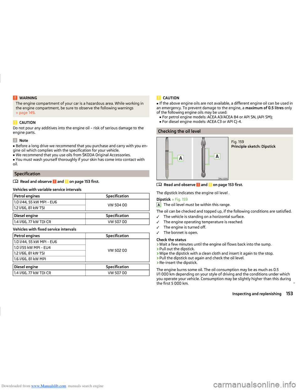
Fig. 159
Principle sketch: Dipstick
Read and observe and on page 153 first.
The dipstick indicates the engine oil level .
Dipstick » Fig. 159
The oil level must be within this range.
The oil can be checked and topped up, if the following conditions are satisfied. The vehicle is standing on a horizontal surface.
The engine operating temperature is reached.
The engine is turned off.
The bonnet is open.
Check the status
›
Wait a few minutes until the engine oil flows back into the sump.
›
Pull out the dipstick.
›
Wipe the dipstick with a clean cloth and insert it again to the stop.
›
Pull the dipstick out again and check the oil level.
›
Re-insert the dipstick.
The engine burns some oil. The oil consumption may be as much as 0.5
l/1 000 km depending on your style of driving and the conditions under which
you operate your vehicle. Consumption may be slightly higher than this during
the first 5 000 km.
A153Inspecting and replenishing
Page 159 of 216
Downloaded from www.Manualslib.com manuals search engine CAUTION■Do not continue your journey if the fluid level has dropped below the “MIN”
marking » Fig. 161 on page 156 , - there is a risk of an accident! Seek help
from a specialist garage.■
Brake fluid damages the paintwork of the vehicle.
Note
■ The brake fluid is changed as part of a prescribed inspection service.■We recommend using oils from the ŠKODA Original Accessories range.
Level check
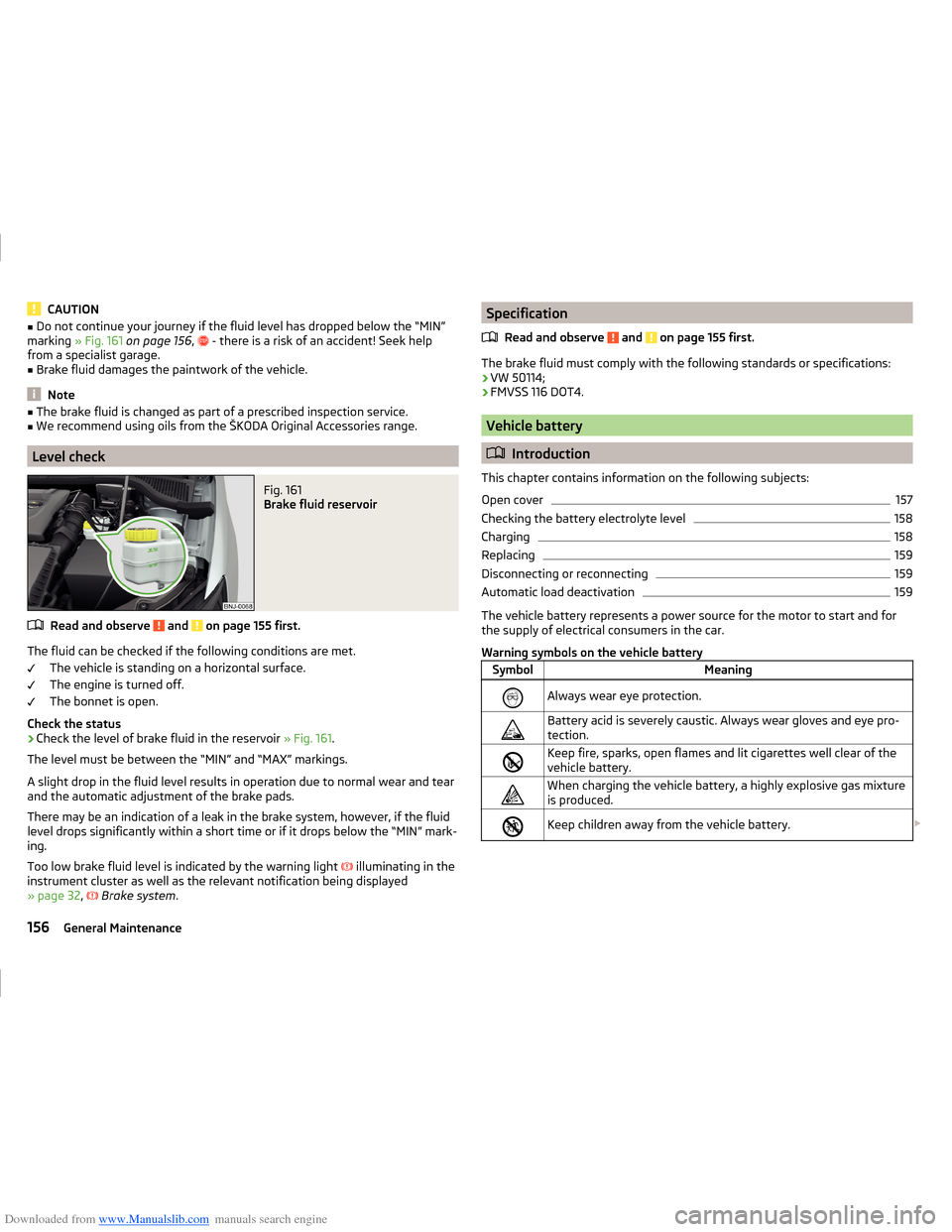
Fig. 161
Brake fluid reservoir
Read and observe and on page 155 first.
The fluid can be checked if the following conditions are met.
The vehicle is standing on a horizontal surface.
The engine is turned off.
The bonnet is open.
Check the status
›
Check the level of brake fluid in the reservoir » Fig. 161.
The level must be between the “MIN” and “MAX” markings.
A slight drop in the fluid level results in operation due to normal wear and tear
and the automatic adjustment of the brake pads.
There may be an indication of a leak in the brake system, however, if the fluid level drops significantly within a short time or if it drops below the “MIN” mark-
ing.
Too low brake fluid level is indicated by the warning light
illuminating in the
instrument cluster as well as the relevant notification being displayed
» page 32 ,
Brake system .
Specification
Read and observe
and on page 155 first.
The brake fluid must comply with the following standards or specifications:› VW 50114;
› FMVSS 116 DOT4.
Vehicle battery
Introduction
This chapter contains information on the following subjects:
Open cover
157
Checking the battery electrolyte level
158
Charging
158
Replacing
159
Disconnecting or reconnecting
159
Automatic load deactivation
159
The vehicle battery represents a power source for the motor to start and for
the supply of electrical consumers in the car.
Warning symbols on the vehicle battery
SymbolMeaningAlways wear eye protection.Battery acid is severely caustic. Always wear gloves and eye pro-
tection.Keep fire, sparks, open flames and lit cigarettes well clear of the
vehicle battery.When charging the vehicle battery, a highly explosive gas mixture
is produced.Keep children away from the vehicle battery. 156General Maintenance
Page 161 of 216
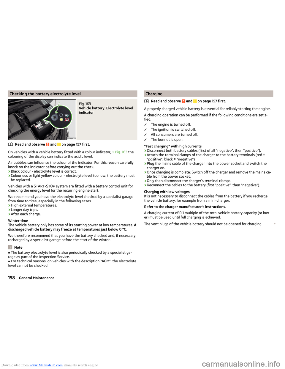
Downloaded from www.Manualslib.com manuals search engine Checking the battery electrolyte levelFig. 163
Vehicle battery: Electrolyte level
indicator
Read and observe and on page 157 first.
On vehicles with a vehicle battery fitted with a colour indicator, » Fig. 163 the
colouring of the display can indicate the acidic level.
Air bubbles can influence the colour of the indicator. For this reason carefully knock on the indicator before carrying out the check.
› Black colour - electrolyte level is correct.
› Colourless or light yellow colour - electrolyte level too low, the battery must
be replaced.
Vehicles with a START-STOP system are fitted with a battery control unit for
checking the energy level for the recurring engine start.
We recommend you have the electrolyte level checked by a specialist garage from time to time, especially in the following cases.
› High external temperatures.
› Longer day trips.
› After each charge.
Winter time
The vehicle battery only has some of its starting power at low temperatures. A
discharged vehicle battery may freeze at temperatures just below 0 °C .
We therefore recommend that you have the battery checked and, if necessary,
recharged by a specialist garage before the start of the winter.
Note
■ The battery electrolyte level is also periodically checked by a specialist ga-
rage as part of the Inspection Service.■
For technical reasons, on vehicles with the description “AGM”, the electrolyte
level cannot be checked.
Charging
Read and observe
and on page 157 first.
A properly charged vehicle battery is essential for reliably starting the engine.A charging operation can be performed if the following conditions are satis-
fied.
The engine is turned off.
The ignition is switched off.
All consumers are turned off.
The bonnet is open.
“Fast charging” with high currents
›
Disconnect both battery cables (first of all “negative”, then “positive”).
›
Attach the terminal clamps of the charger to the battery terminals (red =
“positive”, black = “negative”).
›
Plug the mains cable of the charger into the power socket and switch the
charger on.
›
Once charging is complete: Switch off the charger and remove the mains ca-
ble from the power socket.
›
Only then disconnect the charger's terminal clamps.
›
Reconnect the cables to the battery (first “positive”, then “negative”).
Charging with low voltages
It is not necessary to disconnect the cables from the battery if you recharge
the vehicle battery, for example from a mini-charger.
Refer to the charger manufacturer's instructions .
A charging current of 0.1 multiple of the total vehicle battery capacity (or low-
er) must be used until full charging is achieved.
The vent plugs of the vehicle battery should not be opened for charging.
158General Maintenance
Page 163 of 216
Downloaded from www.Manualslib.com manuals search engine CAUTION■Despite such intervention by the vehicle electric system management, the
vehicle battery may be drained. For example, when the ignition is switched on
a long time with the engine turned off or the side or parking lights are turned
on during longer parking.■
Consumers which are supplied via a 12 V socket can cause the vehicle battery
to discharge when the ignition is switched off.
Note
Driving comfort is not disrupted by any shutting off of consumers. Often the
driver is not aware of it having taken place.Wheels
Tyres and rims
Introduction
This chapter contains information on the following subjects:
Notes on using wheels
161
Tyre pressure
161
Tyre wear
162
Tyre wear indicator and wheels exchange
162
Tyre damage
163
Unidirectional tyres
163
Spare wheel
163
Spare wheel
163
Tyre label
164
Only use those tyres or wheel rims which have been approved by ŠKODA for
your model of vehicle.
WARNINGNational legal requirements must be observed for the use of tyres.WARNINGFor safety reasons, do no replace tyres individually.
For the sake of the environment
Old and unserviceable tyres are a polluting hazardous waste. These must be disposed of in accordance with national legislation.
Note
■ We recommend that any work on the wheels or tyres is carried out by a spe-
cialist garage.■
We recommend that you use wheel rims, tyres, full wheel trims and snow
chains from ŠKODA Original Accessories.
160General Maintenance
Page 164 of 216
Downloaded from www.Manualslib.com manuals search engine Notes on using wheelsRead and observe
on page 160 first.
During the first 500 km, new tyres do not offer optimum grip and appropriate
care should therefore be taken when driving.
Always fit the tyres with the deeper tread depth to the front wheels.
Tyre storage
Mark the tyres as you remove them so that you are able to refit them to run in
the same direction.
Always store wheels or tyres in a cool, dry and, where possible, dark place.
Tyres which are not fixed to a wheel trim should be stored upright.
Tyre age
Tyres age losing their original characteristics, even if they are not used. The
service life of the tyres is 6 years. Therefore, we recommend not using tyres
older than 6 years.
Wheel bolts
Wheels and wheel bolts are matched to each other in terms of design. There-
fore we recommend that you use wheel rims and wheel bolts from ŠKODA
Original Accessories.
WARNINGNever use tyres if you do not know anything about the condition and age.
Tyre pressure
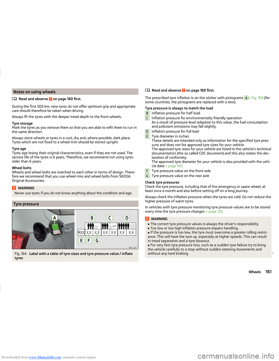
Fig. 164
Label with a table of tyre sizes and tyre pressure value / inflate
tyres
Read and observe on page 160 first.
The prescribed tyre inflation is on the sticker with pictograms
A
» Fig. 164 (for
some countries, the pictograms are replaced with a text).
Tyre pressure is always to match the load .
Inflation pressure for half load
Inflation pressure for environmentally-friendly operation
As a result of pressure level adaption to this value, the fuel consumption
and pollutant emissions may fall slightly.
Inflation pressure for full load
Tyre diameter in inches
These details are intended only as information for the specified tyre pres-
sure and does not list approved tyre sizes for your vehicle.
The approved tyre sizes for your vehicle are listed in the vehicle's technical
documentation (the so called COC document) and this also states the dec-
laration of conformity.
The approved tyre diameter for your vehicle is also provided with the vehi-
cle data » page 192 .
Tyre pressure value on the front axle
Tyre pressure value on the rear axle
Check tyre pressures
Check the tyre pressure, including that of the emergency or spare wheel, at
least once a month and also before setting off on a long journey.
Always check the inflation pressure when the tyres are cold. Do not reduce the
higher pressure of warm tyres.
In vehicles with tyre pressure monitoring tyre pressure values are to be stored
every time the tyre pressure changes » page 125.
WARNING■
The correct tyre pressure values is always the driver's responsibility.■Too low or too high inflation pressure impairs handling.■
If the pressure is too low, the tyre must overcome a greater rolling resist-
ance. This will heat the tyre up, especially at higher speeds. This can result
in tread separation and a tyre blowout.
■
For very fast tyre pressure loss, such as a sudden tyre failure try to bring
the vehicle carefully to a stop without sudden steering movements and
without any hard braking.
BCDEFG161Wheels
Page 180 of 216
Downloaded from www.Manualslib.com manuals search engine The cap must engage firmly.
Removing/installing the towing eye›
Manually screw the towing eye as far as it will go in the direction of the ar-
row
3
» Fig. 181 » .
For tightening purposes, we recommend, for example, using the wheel
wrench, towing eye from another vehicle or a similar object that can be pushed through the eye.
›
Unscrew the towing eye against the direction of the arrow
3
.
WARNINGThe towing eye must always be screwed in fully and firmly tightened, oth-
erwise the towing eye can tear when towing in or tow-starting.
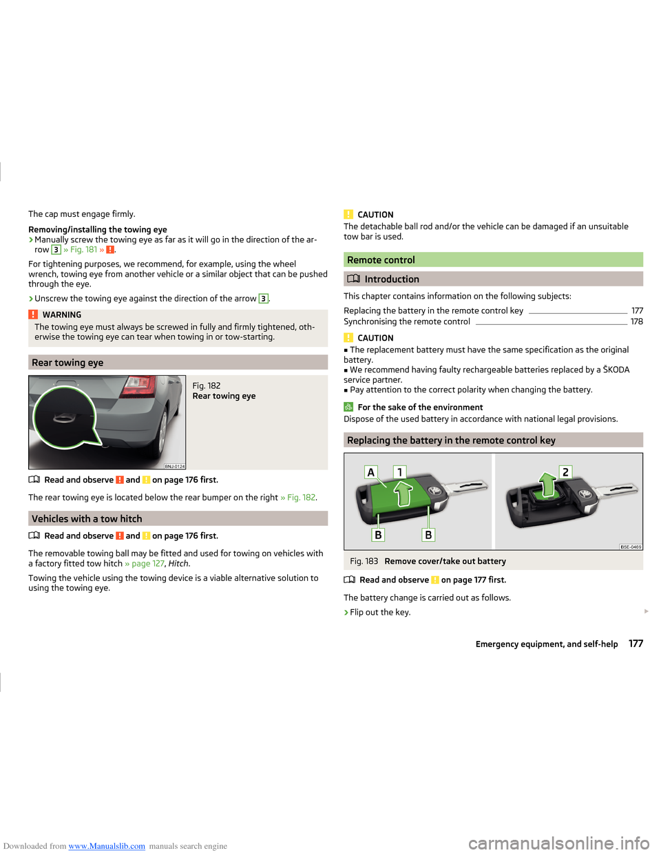
Rear towing eye
Fig. 182
Rear towing eye
Read and observe and on page 176 first.
The rear towing eye is located below the rear bumper on the right » Fig. 182.
Vehicles with a tow hitch
Read and observe
and on page 176 first.
The removable towing ball may be fitted and used for towing on vehicles with
a factory fitted tow hitch » page 127, Hitch .
Towing the vehicle using the towing device is a viable alternative solution to
using the towing eye.
CAUTIONThe detachable ball rod and/or the vehicle can be damaged if an unsuitable
tow bar is used.
Remote control
Introduction
This chapter contains information on the following subjects:
Replacing the battery in the remote control key
177
Synchronising the remote control
178
CAUTION
■ The replacement battery must have the same specification as the original
battery.■
We recommend having faulty rechargeable batteries replaced by a ŠKODA
service partner.
■
Pay attention to the correct polarity when changing the battery.
For the sake of the environment
Dispose of the used battery in accordance with national legal provisions.
Replacing the battery in the remote control key
Fig. 183
Remove cover/take out battery
Read and observe
on page 177 first.
The battery change is carried out as follows.
›
Flip out the key.
177Emergency equipment, and self-help
Page 183 of 216
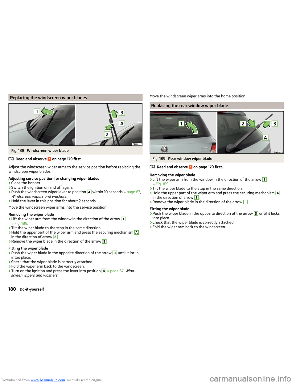
Downloaded from www.Manualslib.com manuals search engine Replacing the windscreen wiper bladesFig. 188
Windscreen wiper blade
Read and observe
on page 179 first.
Adjust the windscreen wiper arms to the service position before replacing the windscreen wiper blades.
Adjusting service position for changing wiper blades
›
Close the bonnet.
›
Switch the ignition on and off again.
›
Push the windscreen wiper lever to position
4
within 10 seconds » page 67,
Windscreen wipers and washers .
›
Hold the lever in this position for about 2 seconds.
Move the windscreen wiper arms into the service position.
Removing the wiper blade
›
Lift the wiper arm from the window in the direction of the arrow
1
» Fig. 188 .
›
Tilt the wiper blade to the stop in the same direction.
›
Hold the upper part of the wiper arm and press the securing mechanism
A
in the direction of arrow
2
.
›
Remove the wiper blade in the direction of the arrow
3
.
Fitting the wiper blade
›
Push the wiper blade in the opposite direction of the arrow
3
until it locks
intoo place.
›
Check that the wiper blade is correctly attached.
›
Fold the wiper arm back to the windscreen.
›
Turn on the ignition and press the lever into position
4
» page 67 , Wind-
screen wipers and washers .
Move the windscreen wiper arms into the home position.
Replacing the rear window wiper blade
Fig. 189
Rear window wiper blade
Read and observe
on page 179 first.
Removing the wiper blade
›
Lift the wiper arm from the window in the direction of the arrow
1
» Fig. 189 .
›
Tilt the wiper blade to the stop in the same direction.
›
Hold the upper part of the wiper arm and press the securing mechanism
A
in the direction of arrow
2
.
›
Remove the wiper blade in the direction of the arrow
3
.
Fitting the wiper blade
›
Push the wiper blade in the opposite direction of the arrow
3
until it locks
into place.
›
Check that the wiper blade is correctly attached.
›
Fold the wiper arm back to the windscreen.
180Do-it-yourself
Page 195 of 216
Downloaded from www.Manualslib.com manuals search engine Technical data
Technical data
Vehicle data
Introduction
This chapter contains information on the following subjects:
Vehicle characteristics
192
Operating weight and payload
193
measurement of fuel consumption and CO 2 emissions according to ECE
Regulations and EU Directives
193
Dimensions
194
Departure angle
195
Vehicle-specific details per engine type
196
The details given in the vehicle's technical documentation always take prece-
dence over the details in the Owner's Manual.
The listed performance values were determined without performance-reduc- ing equipment, e.g. air conditioning system.
Vehicle characteristics
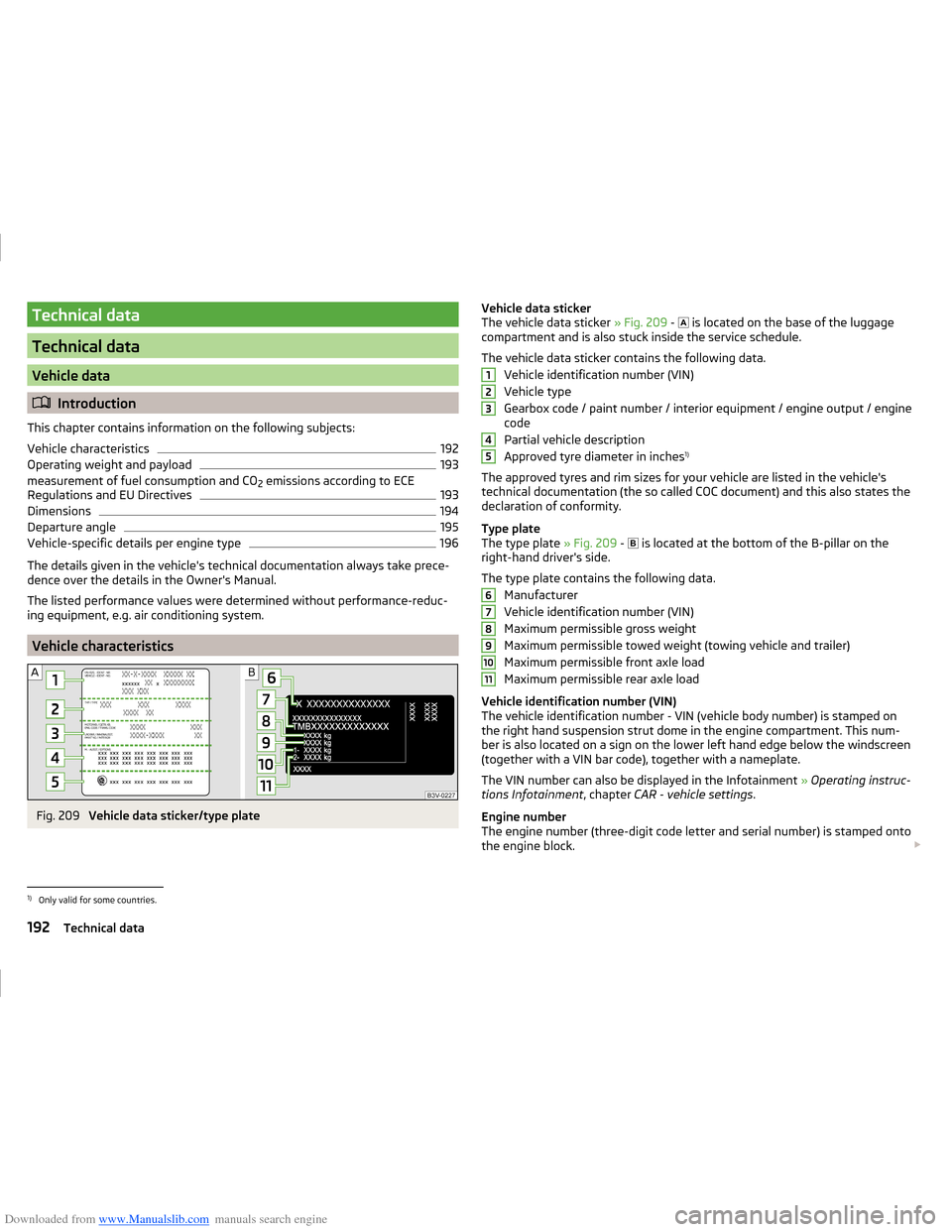
Fig. 209
Vehicle data sticker/type plate
Vehicle data sticker
The vehicle data sticker » Fig. 209 - is located on the base of the luggage
compartment and is also stuck inside the service schedule.
The vehicle data sticker contains the following data. Vehicle identification number (VIN)
Vehicle type
Gearbox code / paint number / interior equipment / engine output / engine code
Partial vehicle description
Approved tyre diameter in inches 1)
The approved tyres and rim sizes for your vehicle are listed in the vehicle's
technical documentation (the so called COC document) and this also states the
declaration of conformity.
Type plate
The type plate » Fig. 209 -
is located at the bottom of the B-pillar on the
right-hand driver's side.
The type plate contains the following data. Manufacturer
Vehicle identification number (VIN)
Maximum permissible gross weight
Maximum permissible towed weight (towing vehicle and trailer)
Maximum permissible front axle load
Maximum permissible rear axle load
Vehicle identification number (VIN)
The vehicle identification number - VIN (vehicle body number) is stamped on
the right hand suspension strut dome in the engine compartment. This num-
ber is also located on a sign on the lower left hand edge below the windscreen
(together with a VIN bar code), together with a nameplate.
The VIN number can also be displayed in the Infotainment » Operating instruc-
tions Infotainment , chapter CAR - vehicle settings .
Engine number
The engine number (three-digit code letter and serial number) is stamped onto
the engine block. 12345678910111)
Only valid for some countries.
192Technical data
Page 205 of 216
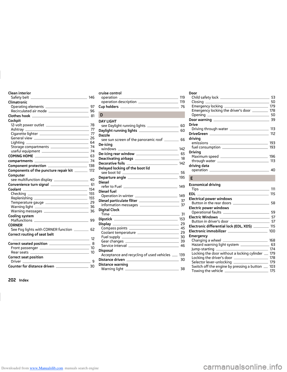
Downloaded from www.Manualslib.com manuals search engine Clean interiorSafety belt146
Climatronic Operating elements
97
Recirculated air mode96
Clothes hook81
Cockpit 12-volt power outlet
78
Ashtray77
Cigarette lighter77
General view26
Lighting64
Storage compartments74
useful equipment74
COMING HOME63
compartments74
Component protection138
Components of the puncture repair kit172
Computer see multifunction display
40
Convenience turn signal61
Coolant154
Checking155
Replenishing155
Temperature gauge29
Warning light36
Warning messages36
Cooling system Malfunctions
99
CORNER See Fog lights with CORNER function
62
Correct routing of seat belt
12
Correct seated position8
Front passenger10
Rear seats10
Correct seat position Driver
9
Counter for distance driven30
cruise control operation119
operation description119
Cup holders76
D
DAY LIGHT see Daylight running lights
60
Daylight running lights60
Dazzle see sun screen of the panoramic roof
66
De-icing windows
142
De-icing rear window65
Deactivating airbags18
Decorative foils142
Delayed locking of the boot lid see boot lid
56
Departure angle195
Diesel refer to Fuel
149
Diesel fuel Operation in winter
149
Diesel particulate filter37
information messages37
Digital Clock Time
31
Dipstick153
Display29
Compass points45
Coolant temperature29
Fuel supply30
Gear changes39
Service interval46
Disposal Acceptance and recycling of used vehicles
139
Distance driven30
Distance warning Warning light
38
DoorChild safety lock53
Closing50
Emergency locking179
Emergency locking the driver's door178
Opening50
Door warning39
Drive Driving through water
113
DriveGreen112
driving emissions
193
fuel consumption193
Driving Maximum speed
196
through water113
driving data operation
40
E
Economical driving Tips
111
EDL115
Electrical power windows Button in the rear doors
58
Electric power windows Operational faults
59
Electric Windows57
Button in driver's door57
Electronic differential lock (EDL, XDS)115
Electronic immobilizer100
Emergency Changing a wheel
168
Hazard warning light system63
Jump-starting174
Locking the door without a locking cylinder179
Locking the driver's door178
Selector lever-unlocking179
Switch off the engine by pressing a button103
Towing the vehicle175
202Index
Page 207 of 216
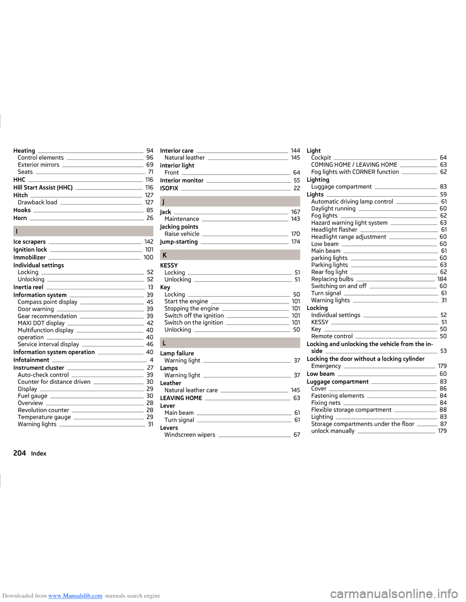
Downloaded from www.Manualslib.com manuals search engine Heating94
Control elements96
Exterior mirrors69
Seats71
HHC116
Hill Start Assist (HHC)116
Hitch127
Drawback load127
Hooks85
Horn26
I
Ice scrapers
142
Ignition lock101
Immobilizer100
Individual settings Locking
52
Unlocking52
Inertia reel13
Information system39
Compass point display45
Door warning39
Gear recommendation39
MAXI DOT display42
Multifunction display40
operation40
Service interval display46
Information system operation40
Infotainment4
Instrument cluster27
Auto-check control39
Counter for distance driven30
Display29
Fuel gauge30
Overview28
Revolution counter28
Temperature gauge29
Warning lights31
Interior care144
Natural leather145
interior light Front
64
Interior monitor55
ISOFIX22
J
Jack
167
Maintenance143
Jacking points Raise vehicle
170
Jump-starting174
K
KESSY Locking
51
Unlocking51
Key Locking
50
Start the engine101
Stopping the engine101
Switch off the ignition101
Switch on the ignition101
Unlocking50
L
Lamp failure Warning light
37
Lamps Warning light
37
Leather Natural leather care
145
LEAVING HOME63
Lever Main beam
61
Turn signal61
Levers Windscreen wipers
67
LightCockpit64
COMING HOME / LEAVING HOME63
Fog lights with CORNER function62
Lighting Luggage compartment
83
Lights59
Automatic driving lamp control61
Daylight running60
Fog lights62
Hazard warning light system63
Headlight flasher61
Headlight range adjustment60
Low beam60
Main beam61
parking lights60
Parking lights63
Rear fog light62
Replacing bulbs184
Switching on and off60
Turn signal61
Warning lights31
Locking Individual settings
52
KESSY51
Key50
Remote control50
Locking and unlocking the vehicle from the in- side
53
Locking the door without a locking cylinder Emergency
179
Low beam60
Luggage compartment83
Cover86
Fastening elements84
Fixing nets84
Flexible storage compartment88
Lighting83
Storage compartments under the floor87
unlock manually179
204Index