ignition SKODA FABIA 2014 3.G / NJ Operating Instruction Manual
[x] Cancel search | Manufacturer: SKODA, Model Year: 2014, Model line: FABIA, Model: SKODA FABIA 2014 3.G / NJPages: 216, PDF Size: 30.9 MB
Page 69 of 216
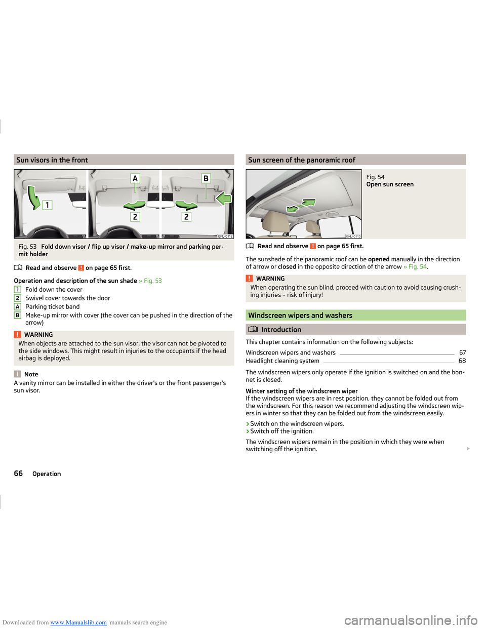
Downloaded from www.Manualslib.com manuals search engine Sun visors in the frontFig. 53
Fold down visor / flip up visor / make-up mirror and parking per-
mit holder
Read and observe
on page 65 first.
Operation and description of the sun shade » Fig. 53
Fold down the cover
Swivel cover towards the door
Parking ticket band
Make-up mirror with cover (the cover can be pushed in the direction of the
arrow)
WARNINGWhen objects are attached to the sun visor, the visor can not be pivoted to
the side windows. This might result in injuries to the occupants if the head
airbag is deployed.
Note
A vanity mirror can be installed in either the driver's or the front passenger's
sun visor.12ABSun screen of the panoramic roofFig. 54
Open sun screen
Read and observe on page 65 first.
The sunshade of the panoramic roof can be opened manually in the direction
of arrow or closed in the opposite direction of the arrow » Fig. 54.
WARNINGWhen operating the sun blind, proceed with caution to avoid causing crush-
ing injuries – risk of injury!
Windscreen wipers and washers
Introduction
This chapter contains information on the following subjects:
Windscreen wipers and washers
67
Headlight cleaning system
68
The windscreen wipers only operate if the ignition is switched on and the bon-
net is closed.
Winter setting of the windscreen wiper
If the windscreen wipers are in rest position, they cannot be folded out from
the windscreen. For this reason we recommend adjusting the windscreen wip-
ers in winter so that they can be folded out from the windscreen easily.
› Switch on the windscreen wipers.
› Switch off the ignition.
The windscreen wipers remain in the position in which they were when
switching off the ignition.
66Operation
Page 70 of 216
Downloaded from www.Manualslib.com manuals search engine The service position can also be used as a winter position » page 180, Replac-
ing the windscreen wiper blades .WARNING■
Properly maintained windscreen wiper blades are essential for clear visi-
bility and safe driving » page 179, Replacing windscreen wiper blades .■
Do not use the windscreen washer system at low temperatures without
heating the windscreen beforehand. The window washer fluid could other-
wise freeze on the windscreen and restrict the view to the front.
CAUTION
■ In cold temperatures and during the winter, check before switching on the
ignition that the wiper blades are not frozen to the windscreen. If the wind-
screen wipers are switched on when the blades are frozen to the windscreen,
this may damage both the blades and windscreen wiper motor!■
Carefully release frozen wiper blades off the windscreen.
■
Remove snow and ice from the windscreen wipers before driving.
■
If the windscreen wipers are handled carelessly, there is a risk of damage to
the windscreen.
■
Do not switch on the ignition if the front wiper arms are retracted. The wiper
arms could damage the paint of the bonnet.
Note
The windscreen washer nozzles of the windscreen are heated automatically
after starting the engine.
Windscreen wipers and washers
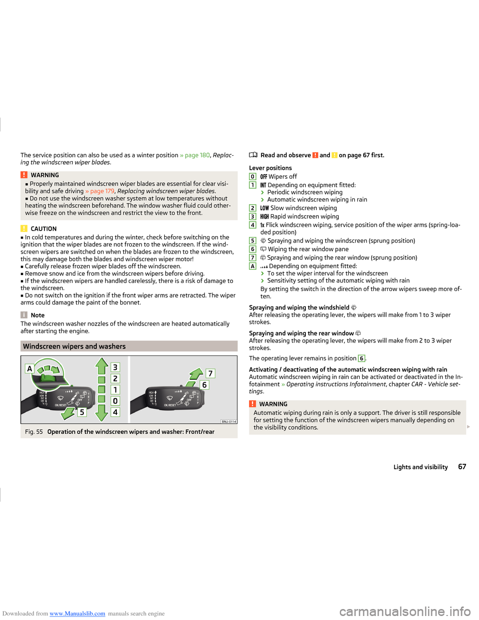
Fig. 55
Operation of the windscreen wipers and washer: Front/rear
Read and observe and on page 67 first.
Lever positions
Wipers off
Depending on equipment fitted:
› Periodic windscreen wiping
› Automatic windscreen wiping in rain
Slow windscreen wiping
Rapid windscreen wiping
Flick windscreen wiping, service position of the wiper arms (spring-loa-
ded position)
Spraying and wiping the windscreen (sprung position)
Wiping the rear window pane
Spraying and wiping the rear window (sprung position)
Depending on equipment fitted:
› To set the wiper interval for the windscreen
› Sensitivity setting of the automatic wiping with rain
By setting the switch in the direction of the arrow wipers sweep more of-
ten.
Spraying and wiping the windshield
After releasing the operating lever, the wipers will make from 1 to 3 wiper
strokes.
Spraying and wiping the rear window
After releasing the operating lever, the wipers will make from 2 to 3 wiper
strokes.
The operating lever remains in position
6
.
Activating / deactivating of the automatic windscreen wiping with rain
Automatic windscreen wiping in rain can be activated or deactivated in the In-
fotainment » Operating instructions Infotainment , chapter CAR - Vehicle set-
tings .
WARNINGAutomatic wiping during rain is only a support. The driver is still responsible
for setting the function of the windscreen wipers manually depending on
the visibility conditions. 01234567A67Lights and visibility
Page 71 of 216
Downloaded from www.Manualslib.com manuals search engine Note■If the operating lever is in the position 2 or 3 and the speed of the vehicle
drops below 4 km / h, the wiping speed is reduced. The original wiping speed is
restored step by step when the speed of the vehicle exceeds 8 km/h.■
The rear window is wiped once automatically if the windscreen wipers are on
when reverse gear is selected. The function can be enabled or disabled in the
Infotainment » Operating instructions Infotainment , chapter CAR - vehicle set-
tings .
Headlight cleaning system
Read and observe
and on page 67 first.
To clean the headlights, the headlamp is also sprayed after every ten squirts.The headlight washer system works under the following conditions. The ignition is switched on.
The low beam is switched on.
The outside temperature is about -12° C to +39° C.
To ensure the correct functioning of the system, even in winter, this needs to
be regularly cleared of snow and ice, e.g. free with a de-icing spray.
Rear mirror
Introduction
This chapter contains information on the following subjects:
Interior mirror dimming
68
Exterior mirrors
69WARNING■ Convex (curved outward) or aspherical exterior mirrors increase the field
of vision. They do, however, make objects appear smaller in the mirror.
These mirrors are therefore only of limited use for estimating distances to
the following vehicles.■
Whenever possible use the interior mirror for estimating the distances to
the following vehicles.
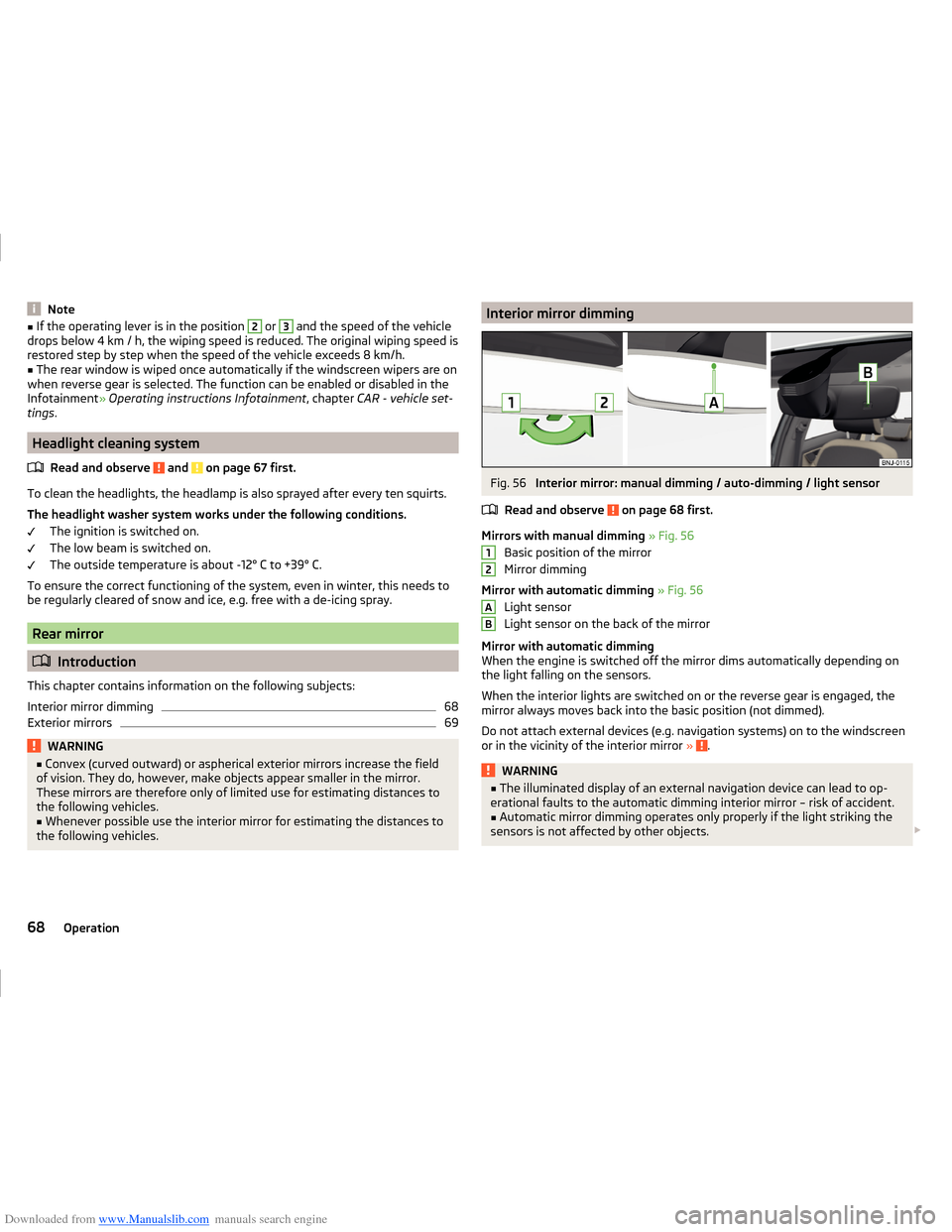
Interior mirror dimmingFig. 56
Interior mirror: manual dimming / auto-dimming / light sensor
Read and observe
on page 68 first.
Mirrors with manual dimming » Fig. 56
Basic position of the mirror
Mirror dimming
Mirror with automatic dimming » Fig. 56
Light sensor
Light sensor on the back of the mirror
Mirror with automatic dimming
When the engine is switched off the mirror dims automatically depending on
the light falling on the sensors.
When the interior lights are switched on or the reverse gear is engaged, the
mirror always moves back into the basic position (not dimmed).
Do not attach external devices (e.g. navigation systems) on to the windscreen
or in the vicinity of the interior mirror »
.
WARNING■
The illuminated display of an external navigation device can lead to op-
erational faults to the automatic dimming interior mirror – risk of accident.■
Automatic mirror dimming operates only properly if the light striking the
sensors is not affected by other objects.
12AB68Operation
Page 74 of 216
Downloaded from www.Manualslib.com manuals search engine Move down›Press the locking button A in the direction of the arrow 2 and hold
» Fig. 59 .›
Push the headrest in the direction of arrow
3
.
WARNINGWith seats occupied, the respective head rests must be correctly set (may
not be in the bottom position) - there is a risk of fatal injury!
Note
■ The middle rear headrest is only adjustable in two positions.■For the sports seats, the headrests are integrated into the front seat backr-
ests. This headrest cannot be adjusted in height.
Headrests - removing and installing
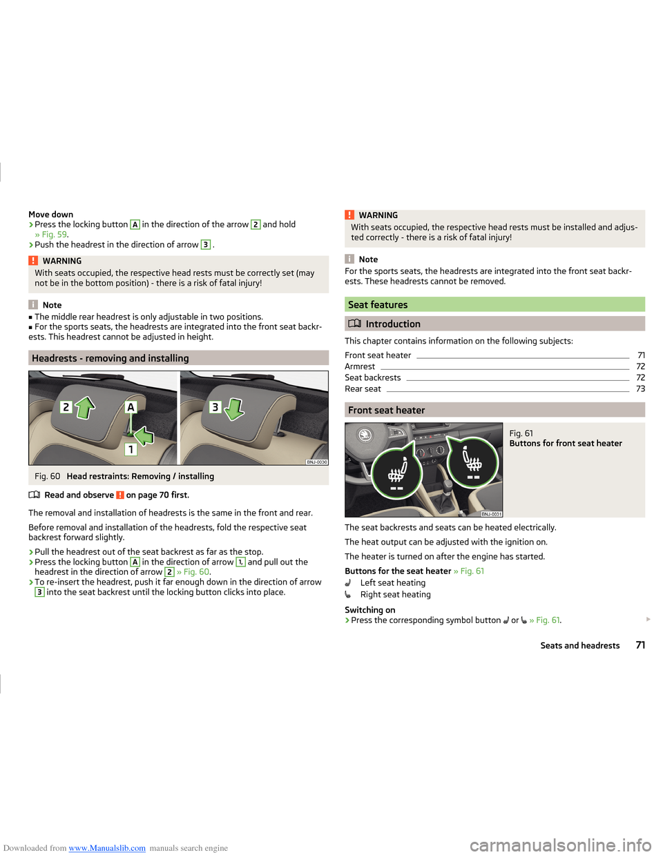
Fig. 60
Head restraints: Removing / installing
Read and observe
on page 70 first.
The removal and installation of headrests is the same in the front and rear.
Before removal and installation of the headrests, fold the respective seat
backrest forward slightly.
›
Pull the headrest out of the seat backrest as far as the stop.
›
Press the locking button
A
in the direction of arrow
1,
and pull out the
headrest in the direction of arrow
2
» Fig. 60 .
›
To re-insert the headrest, push it far enough down in the direction of arrow
3
into the seat backrest until the locking button clicks into place.
WARNINGWith seats occupied, the respective head rests must be installed and adjus-
ted correctly - there is a risk of fatal injury!
Note
For the sports seats, the headrests are integrated into the front seat backr-
ests. These headrests cannot be removed.
Seat features
Introduction
This chapter contains information on the following subjects:
Front seat heater
71
Armrest
72
Seat backrests
72
Rear seat
73
Front seat heater
Fig. 61
Buttons for front seat heater
The seat backrests and seats can be heated electrically.
The heat output can be adjusted with the ignition on.
The heater is turned on after the engine has started.
Buttons for the seat heater » Fig. 61
Left seat heating
Right seat heating
Switching on
›
Press the corresponding symbol button
or
» Fig. 61 .
71Seats and headrests
Page 80 of 216
Downloaded from www.Manualslib.com manuals search engine CAUTIONDo not leave open beverage containers in the cup holder during the journey.
There is a risk of spilling e.g. when braking which may cause damage to the
electrical components or seat upholstery.
Cigarette lighter
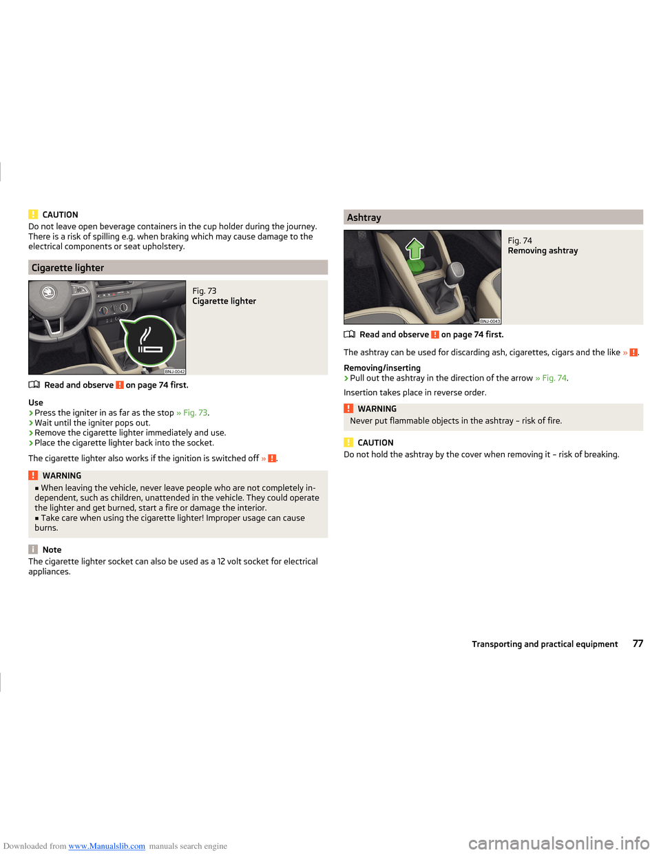
Fig. 73
Cigarette lighter
Read and observe on page 74 first.
Use
›
Press the igniter in as far as the stop » Fig. 73.
›
Wait until the igniter pops out.
›
Remove the cigarette lighter immediately and use.
›
Place the cigarette lighter back into the socket.
The cigarette lighter also works if the ignition is switched off »
.
WARNING■
When leaving the vehicle, never leave people who are not completely in-
dependent, such as children, unattended in the vehicle. They could operate
the lighter and get burned, start a fire or damage the interior.■
Take care when using the cigarette lighter! Improper usage can cause
burns.
Note
The cigarette lighter socket can also be used as a 12 volt socket for electrical
appliances.AshtrayFig. 74
Removing ashtray
Read and observe on page 74 first.
The ashtray can be used for discarding ash, cigarettes, cigars and the like » .
Removing/inserting
›
Pull out the ashtray in the direction of the arrow » Fig. 74.
Insertion takes place in reverse order.
WARNINGNever put flammable objects in the ashtray – risk of fire.
CAUTION
Do not hold the ashtray by the cover when removing it – risk of breaking.77Transporting and practical equipment
Page 81 of 216
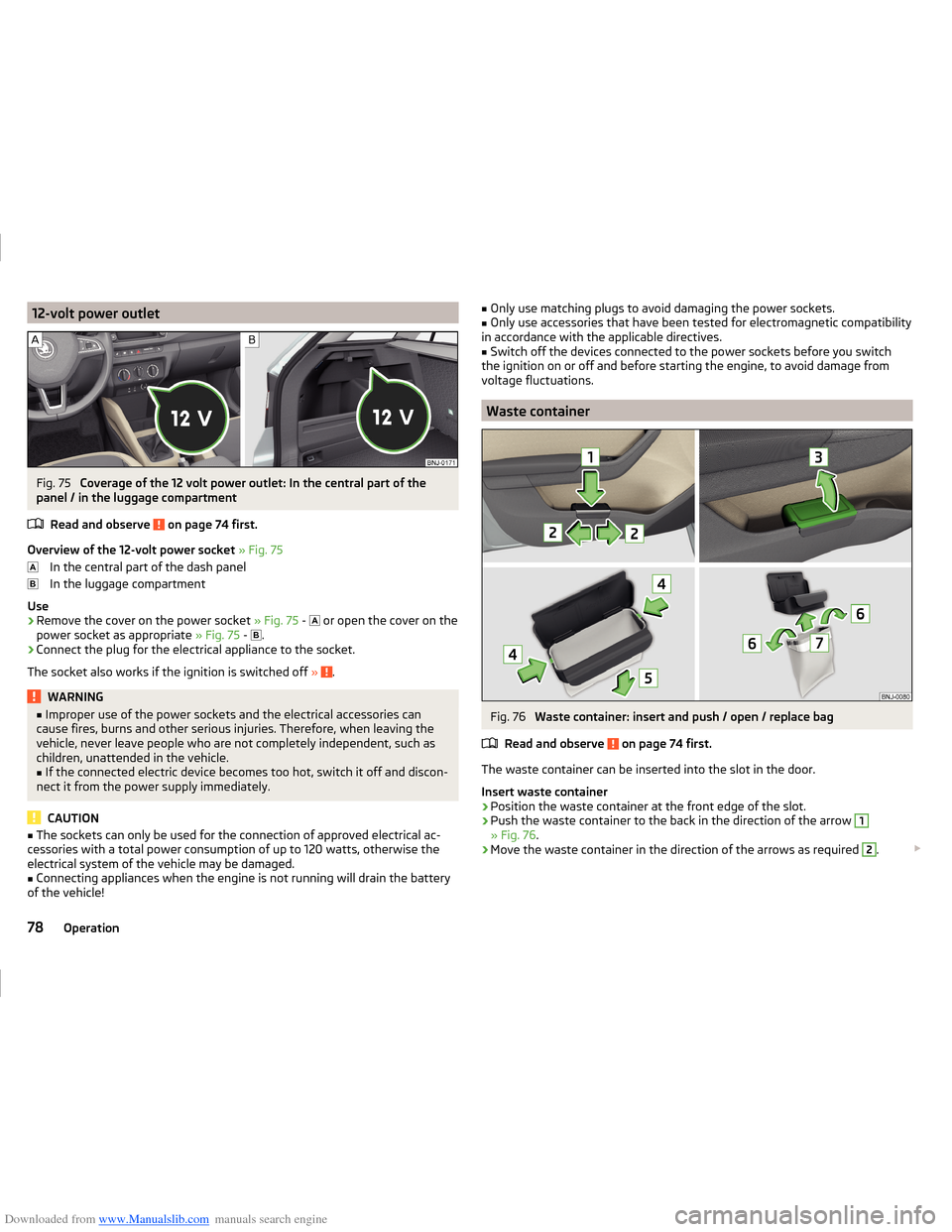
Downloaded from www.Manualslib.com manuals search engine 12-volt power outletFig. 75
Coverage of the 12 volt power outlet: In the central part of the
panel / in the luggage compartment
Read and observe
on page 74 first.
Overview of the 12-volt power socket » Fig. 75
In the central part of the dash panel
In the luggage compartment
Use
›
Remove the cover on the power socket » Fig. 75 -
or open the cover on the
power socket as appropriate » Fig. 75 -
.
›
Connect the plug for the electrical appliance to the socket.
The socket also works if the ignition is switched off »
.
WARNING■
Improper use of the power sockets and the electrical accessories can
cause fires, burns and other serious injuries. Therefore, when leaving the
vehicle, never leave people who are not completely independent, such as
children, unattended in the vehicle.■
If the connected electric device becomes too hot, switch it off and discon-
nect it from the power supply immediately.
CAUTION
■ The sockets can only be used for the connection of approved electrical ac-
cessories with a total power consumption of up to 120 watts, otherwise the
electrical system of the vehicle may be damaged.■
Connecting appliances when the engine is not running will drain the battery
of the vehicle!
■ Only use matching plugs to avoid damaging the power sockets.■Only use accessories that have been tested for electromagnetic compatibility
in accordance with the applicable directives.■
Switch off the devices connected to the power sockets before you switch
the ignition on or off and before starting the engine, to avoid damage from
voltage fluctuations.
Waste container
Fig. 76
Waste container: insert and push / open / replace bag
Read and observe
on page 74 first.
The waste container can be inserted into the slot in the door.
Insert waste container
›
Position the waste container at the front edge of the slot.
›
Push the waste container to the back in the direction of the arrow
1
» Fig. 76 .
›
Move the waste container in the direction of the arrows as required
2
.
78Operation
Page 86 of 216
Downloaded from www.Manualslib.com manuals search engine Luggage compartment
Introduction
This chapter contains information on the following subjects:
Fastening elements
84
Fixing nets
84
Hooks
85
Storage compartments in the luggage compartment
85
Luggage compartment cover
86
Other positions of the luggage compartment cover
86
Roll-up cover
87
Storage compartments under the floor
87
Cargo element
88
Flexible storage compartment
88
Class N1 vehicles
88
Please observe the following for the purpose of maintaining good handling
characteristics of your vehicle:
›
Distribute loads as evenly as possible.
›
Place heavy objects as far forward as possible.
›
Attach the items of luggage to the lashing eyes or by using the fixing nets
» page 84 .
In the event of an accident, even small and light objects gain so much kinetic energy that they can cause severe injuries.
The magnitude of the kinetic energy is dependent on the speed at which the
vehicle is travelling and the weight of the object.
Example: In the event of a frontal collision at a speed of 50 km/h, an object
weighing 4.5 kg produces energy corresponding to 20 times its own weight.
This means that it results in a weight of approx. 90 kg “ ”.
Luggage compartment light
The warning light turns on when tailgate is opened.
The warning light turns off when the tailgate is closed.
If the boot lid is open and the ignition switched off, the light will extinguish
automatically after around 10 minutes.
WARNING■ Always store transported objects in the boot and attach them to the lash-
ing eyes.■
Loose objects can be thrown forward during a sudden manoeuvre or in
case of an accident and can injure the occupants or other road users.
■
Loose objects could hit a deployed airbag and injure occupants – risk to
life!
■
Please note that the handling properties of the vehicle may be affected
when transporting heavy objects as the centre of gravity can be shifted –
risk of accident. The speed and style of driving must be adjusted according-
ly.
■
If the items of luggage or objects are attached to the lashing eyes with
unsuitable or damaged lashing straps, injuries can occur in the event of
braking manoeuvres or accidents. To prevent items of luggage from moving
around, always use suitable lashing straps that are firmly attached to the
lashing eyes.
■
Items carried in the luggage compartment must be stowed in such a way
that no objects are able to slip forward under sudden driving manoeuvres
or braking – risk of injury.
■
When transporting objects in the luggage compartment that has been en-
larged by folding the rear seats forward, ensure the safety of the passen-
gers transported on the other rear seats » page 10.
■
Do not drive with the luggage compartment lid open or unlatched, other-
wise exhaust gases may get into the interior of the vehicle – risk of poison-
ing!
■
Do not exceed the permissible axle loads and permissible gross weight of
the vehicle – risk of accident!
■
Do not transport people in the boot!
CAUTION
■ Please ensure that the heating elements for the rear window heater are not
damaged as a result of abrasive objects.■
Tyre pressure must be adjusted to the load » page 161.
83Transporting and practical equipment
Page 97 of 216
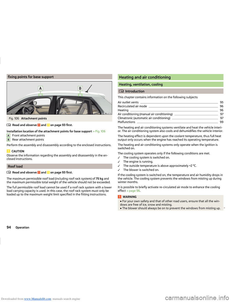
Downloaded from www.Manualslib.com manuals search engine fixing points for base supportFig. 106
Attachment points
Read and observe
and on page 93 first.
Installation location of the attachment points for base support » Fig. 106
Front attachment points
Rear attachment points
Perform the assembly and disassembly according to the enclosed instructions.
CAUTION
Observe the information regarding the assembly and disassembly in the en-
closed instructions.
Roof load
Read and observe
and on page 93 first.
The maximum permissible roof load (including roof rack system) of 75 kg and
the maximum permissible total weight of the vehicle should not be exceeded.
The full permissible roof load cannot be used if a roof rack system with a lower
load carrying capacity is used. In this case, the roof rack system must only be
loaded up to the maximum weight limit specified in the fitting instructions.
ABHeating and air conditioning
Heating, ventilation, cooling
Introduction
This chapter contains information on the following subjects:
Air outlet vents
95
Recirculated air mode
96
Heating
96
Air conditioning (manual air conditioning)
97
Climatronic (automatic air conditioning)
97
Malfunctions
99
The heating and air conditioning systems ventilate and heat the vehicle interi-
or. The air conditioning system also cools and dehumidifies the vehicle interior.
The heating effect is dependent upon the coolant temperature, thus full heat
output only occurs when the engine has reached its operating temperature.
The heating and air conditioning systems only operate when the ignition is
switched on.
The cooling system operates only if the following conditions are met. The cooling system is switched on.
The engine is running.
The outside temperature is above approximately +2 °C.
The blower is switched on.
If the cooling system is switched on, the temperature and air humidity drops in
the vehicle. The cooling system prevents the windows from misting up during
winter months.
It is possible to briefly activate re-circulated air mode to enhance the cooling
effect » page 96 .
WARNING■
For your own safety and that of other road users, ensure that all the win-
dows are free of ice, snow and misting.■
The blower should always be on to prevent the windows from misting up.
94Operation
Page 103 of 216
Downloaded from www.Manualslib.com manuals search engine Driving
Starting-off and driving
Starting and stopping the engine using the key
Introduction
This chapter contains information on the following subjects:
Electronic immobilizer
100
Steering lock locking / unlocking
100
Turn ignition on / off and start the engine
101
Stopping the engine
101
With the key in the ignition, the ignition can be switched on and off and the
engine can be started / stopped.
WARNING■ While driving with the engine stopped, the ignition must always be
switched on » page 101, Turn ignition on / off and start the engine .
■ With the ignition off, the steering may lock » page 100 - danger of an
accident!■
Do not withdraw the ignition key from the ignition lock until the vehicle
has come to a stop » page 107, Parking . Otherwise, the steering may lock -
danger of an accident!
■
Never leave the key in the vehicle when you exit the vehicle. Unauthor-
ized persons such as children could lock the car, turn on the ignition or start
the engine -risk of injury, accidents and damage!
■
Never leave the vehicle unattended with the engine running - risk of acci-
dent, damage or theft!
■
Never switch off the engine before the vehicle has come to a halt – risk of
accident.
WARNING■ Never (e.g. in garages) run the engine in a closed place - risk of poisoning
and death!■
Do not leave any items (e.g. cleaning cloths or tools) in the engine com-
partment. There is a fire hazard and the risk of engine damage.
■
Never cover the engine with additional insulation material (e.g. with a
blanket) – risk of fire.
CAUTION■ Only start the engine when the engine and the vehicle are stationary - risk of
starter and engine damage!■
Do not push-start the engine – there is a risk of damaging the engine and
the catalytic converter. The battery from another vehicle can be used as a
jump-start aid » page 174.
Note
Do not warm up the engine while the vehicle is stationary. If possible, start
your journey as soon as the engine has started. The engine reaches its operat-
ing temperature faster this way.
Electronic immobilizer
Read and observe
and on page 100 first.
The electronic immobilizer makes a possible attempted theft or unauthorizeduse of your vehicle more difficult.
An electronic chip is integrated in the head of the key. The electronic immobil-
iser is deactivated with the aid of this chip when the key is inserted in the igni-
tion lock.
As soon as the ignition key is removed from the ignition lock the immobilizer is
automatically activated.
The engine will not start if an unauthorized ignition key is used.
The following message is shown in the information cluster display. Immobilizer active.
IMMOBILIZER ACTIVE
Steering lock locking / unlocking
Read and observe
and on page 100 first.
The steering lock (steering lock) deters any attempted theft of your vehicle.
Locking
›
Withdraw the ignition key.
›
Turn the steering wheel to the left or right until the steering lock clicks into
place.
Unlocking
›
Insert the key into the ignition lock.
100Driving
Page 104 of 216
Downloaded from www.Manualslib.com manuals search engine ›Switch on the ignition
» page 101.
The steering column lock is unlocked.
If the ignition switch cannot be turned on, turn the steering wheel back and forth slightly to unlock the steering lock.
Turn ignition on / off and start the engine
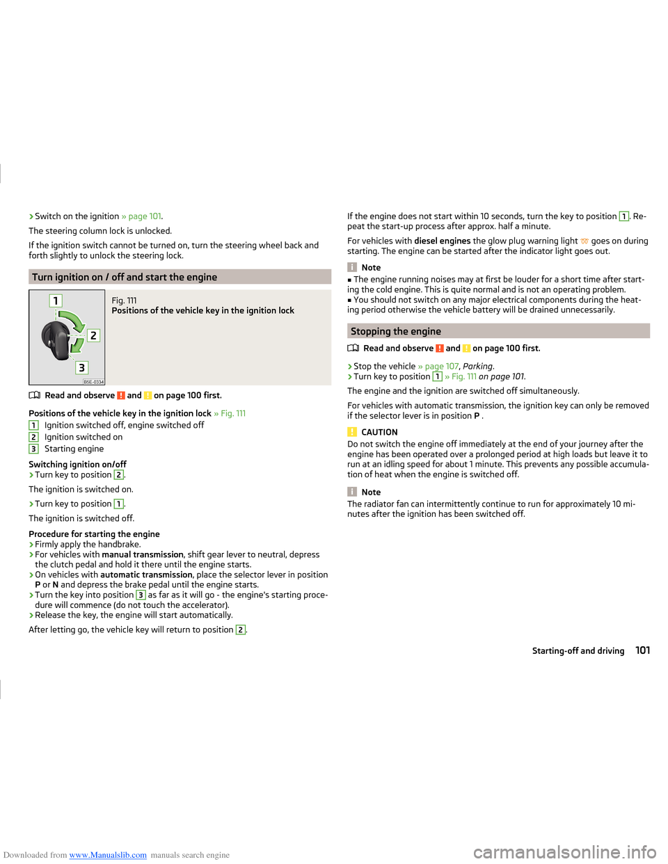
Fig. 111
Positions of the vehicle key in the ignition lock
Read and observe and on page 100 first.
Positions of the vehicle key in the ignition lock » Fig. 111
Ignition switched off, engine switched off
Ignition switched on
Starting engine
Switching ignition on/off
›
Turn key to position
2
.
The ignition is switched on.
›
Turn key to position
1
.
The ignition is switched off.
Procedure for starting the engine
›
Firmly apply the handbrake.
›
For vehicles with manual transmission , shift gear lever to neutral, depress
the clutch pedal and hold it there until the engine starts.
›
On vehicles with automatic transmission , place the selector lever in position
P or N and depress the brake pedal until the engine starts.
›
Turn the key into position
3
as far as it will go - the engine's starting proce-
dure will commence (do not touch the accelerator).
›
Release the key, the engine will start automatically.
After letting go, the vehicle key will return to position
2
.
123If the engine does not start within 10 seconds, turn the key to position 1. Re-
peat the start-up process after approx. half a minute.
For vehicles with diesel engines the glow plug warning light
goes on during
starting. The engine can be started after the indicator light goes out.
Note
■ The engine running noises may at first be louder for a short time after start-
ing the cold engine. This is quite normal and is not an operating problem.■
You should not switch on any major electrical components during the heat-
ing period otherwise the vehicle battery will be drained unnecessarily.
Stopping the engine
Read and observe
and on page 100 first.
›
Stop the vehicle » page 107, Parking .
›
Turn key to position
1
» Fig. 111 on page 101 .
The engine and the ignition are switched off simultaneously.
For vehicles with automatic transmission, the ignition key can only be removed
if the selector lever is in position P .
CAUTION
Do not switch the engine off immediately at the end of your journey after the
engine has been operated over a prolonged period at high loads but leave it to
run at an idling speed for about 1 minute. This prevents any possible accumula-
tion of heat when the engine is switched off.
Note
The radiator fan can intermittently continue to run for approximately 10 mi-
nutes after the ignition has been switched off.101Starting-off and driving