lock SKODA FABIA 2014 3.G / NJ Operating Instruction Manual
[x] Cancel search | Manufacturer: SKODA, Model Year: 2014, Model line: FABIA, Model: SKODA FABIA 2014 3.G / NJPages: 216, PDF Size: 30.9 MB
Page 76 of 216
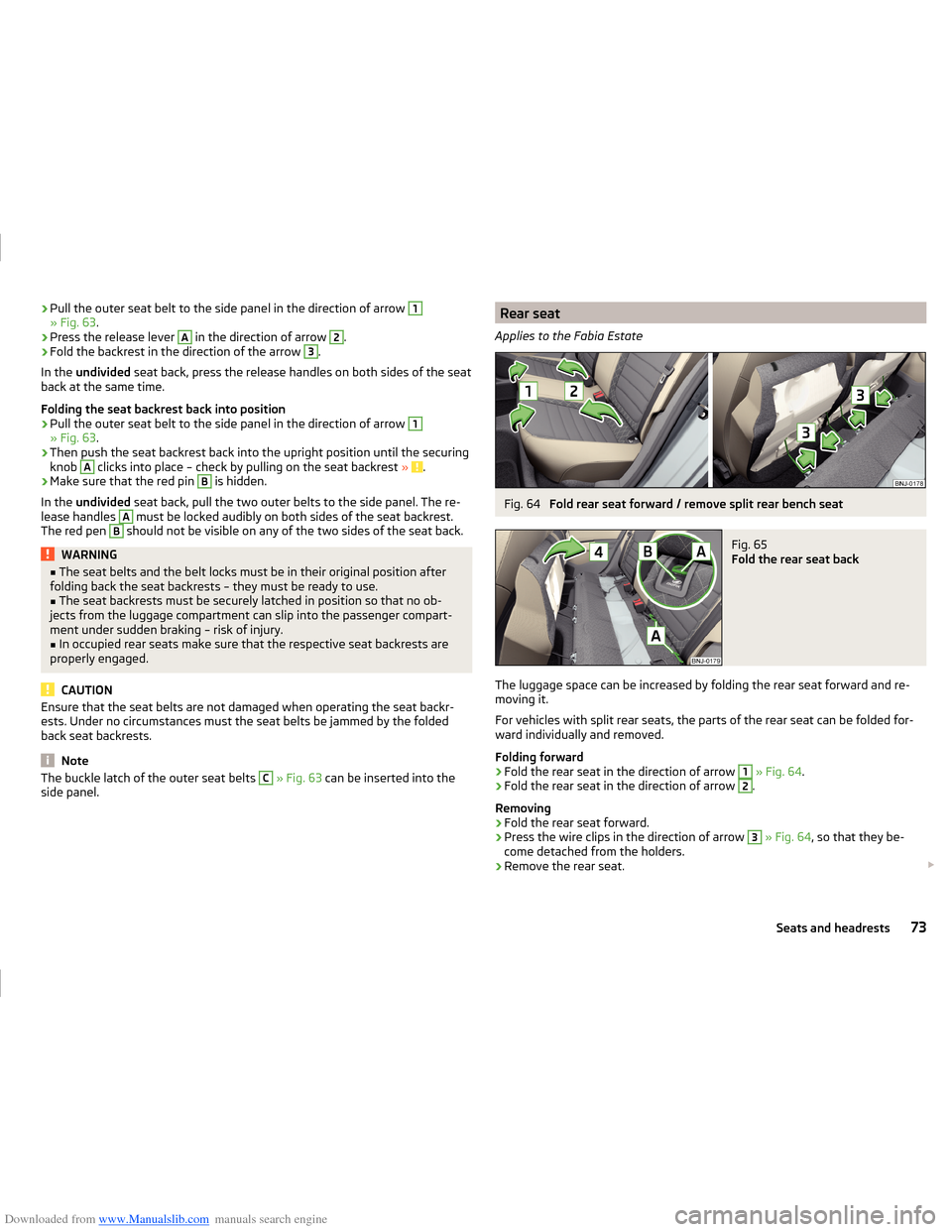
Downloaded from www.Manualslib.com manuals search engine ›Pull the outer seat belt to the side panel in the direction of arrow 1» Fig. 63
.›
Press the release lever
A
in the direction of arrow
2
.
›
Fold the backrest in the direction of the arrow
3
.
In the undivided seat back, press the release handles on both sides of the seat
back at the same time.
Folding the seat backrest back into position
›
Pull the outer seat belt to the side panel in the direction of arrow
1
» Fig. 63 .
›
Then push the seat backrest back into the upright position until the securing
knob
A
clicks into place – check by pulling on the seat backrest » .
›
Make sure that the red pin
B
is hidden.
In the undivided seat back, pull the two outer belts to the side panel. The re-
lease handles
A
must be locked audibly on both sides of the seat backrest.
The red pen
B
should not be visible on any of the two sides of the seat back.
WARNING■ The seat belts and the belt locks must be in their original position after
folding back the seat backrests – they must be ready to use.■
The seat backrests must be securely latched in position so that no ob-
jects from the luggage compartment can slip into the passenger compart-
ment under sudden braking – risk of injury.
■
In occupied rear seats make sure that the respective seat backrests are
properly engaged.
CAUTION
Ensure that the seat belts are not damaged when operating the seat backr-
ests. Under no circumstances must the seat belts be jammed by the folded
back seat backrests.
Note
The buckle latch of the outer seat belts C » Fig. 63 can be inserted into the
side panel.Rear seat
Applies to the Fabia EstateFig. 64
Fold rear seat forward / remove split rear bench seat
Fig. 65
Fold the rear seat back
The luggage space can be increased by folding the rear seat forward and re-
moving it.
For vehicles with split rear seats, the parts of the rear seat can be folded for-
ward individually and removed.
Folding forward
›
Fold the rear seat in the direction of arrow
1
» Fig. 64 .
›
Fold the rear seat in the direction of arrow
2
.
Removing
›
Fold the rear seat forward.
›
Press the wire clips in the direction of arrow
3
» Fig. 64 , so that they be-
come detached from the holders.
›
Remove the rear seat.
73Seats and headrests
Page 82 of 216
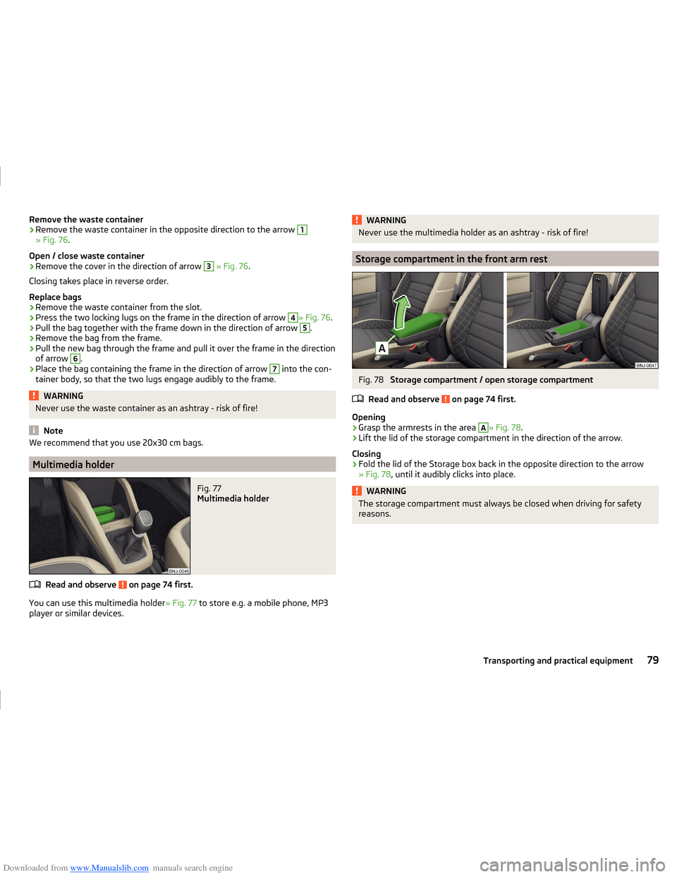
Downloaded from www.Manualslib.com manuals search engine Remove the waste container›Remove the waste container in the opposite direction to the arrow 1
» Fig. 76.
Open / close waste container
›
Remove the cover in the direction of arrow
3
» Fig. 76 .
Closing takes place in reverse order.
Replace bags
›
Remove the waste container from the slot.
›
Press the two locking lugs on the frame in the direction of arrow
4
» Fig. 76 .
›
Pull the bag together with the frame down in the direction of arrow
5
.
›
Remove the bag from the frame.
›
Pull the new bag through the frame and pull it over the frame in the direction
of arrow
6
.
›
Place the bag containing the frame in the direction of arrow
7
into the con-
tainer body, so that the two lugs engage audibly to the frame.
WARNINGNever use the waste container as an ashtray - risk of fire!
Note
We recommend that you use 20x30 cm bags.
Multimedia holder
Fig. 77
Multimedia holder
Read and observe on page 74 first.
You can use this multimedia holder » Fig. 77 to store e.g. a mobile phone, MP3
player or similar devices.
WARNINGNever use the multimedia holder as an ashtray - risk of fire!
Storage compartment in the front arm rest
Fig. 78
Storage compartment / open storage compartment
Read and observe
on page 74 first.
Opening
›
Grasp the armrests in the area
A
» Fig. 78 .
›
Lift the lid of the storage compartment in the direction of the arrow.
Closing
›
Fold the lid of the Storage box back in the opposite direction to the arrow
» Fig. 78 , until it audibly clicks into place.
WARNINGThe storage compartment must always be closed when driving for safety
reasons.79Transporting and practical equipment
Page 83 of 216
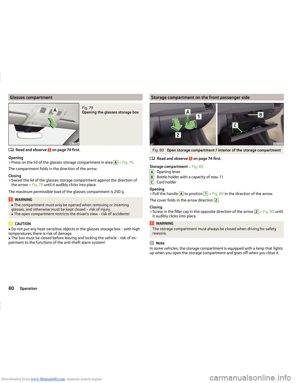
Downloaded from www.Manualslib.com manuals search engine Glasses compartmentFig. 79
Opening the glasses storage box
Read and observe on page 74 first.
Opening
›
Press on the lid of the glasses storage compartment in area
A
» Fig. 79 .
The compartment folds in the direction of the arrow.
Closing
›
Swivel the lid of the glasses storage compartment against the direction of
the arrow » Fig. 79 until it audibly clicks into place.
The maximum permissible load of the glasses compartment is 250 g.
WARNING■ The compartment must only be opened when removing or inserting
glasses, and otherwise must be kept closed – risk of injury.■
The open compartment restricts the driver's view - risk of accidents!
CAUTION
■ Do not put any heat-sensitive objects in the glasses storage box - with high
temperatures there is risk of damage.■
The box must be closed before leaving and locking the vehicle - risk of im-
pairment to the functions of the anti-theft alarm system!
Storage compartment on the front passenger sideFig. 80
Open storage compartment / interior of the storage compartment
Read and observe
on page 74 first.
Storage compartment » Fig. 80
Opening lever
Bottle holder with a capacity of max. 1 l
Card holder
Opening
›
Pull the handle
A
to position
1
» Fig. 80 in the direction of the arrow.
The cover folds in the arrow direction
2
.
Closing
›
Screw in the filler cap in the opposite direction of the arrow
2
» Fig. 80 until
it audibly clicks into place.
WARNINGThe storage compartment must always be closed when driving for safety
reasons.
Note
In some vehicles, the storage compartment is equipped with a lamp that lights
up when you open the storage compartment and goes off when you close it.ABC80Operation
Page 89 of 216
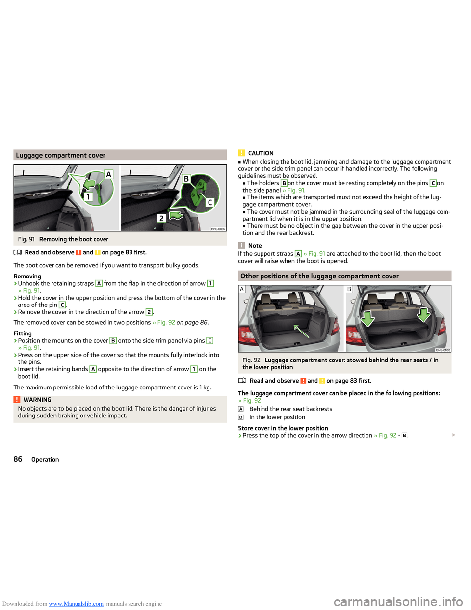
Downloaded from www.Manualslib.com manuals search engine Luggage compartment coverFig. 91
Removing the boot cover
Read and observe
and on page 83 first.
The boot cover can be removed if you want to transport bulky goods.
Removing
›
Unhook the retaining straps
A
from the flap in the direction of arrow
1
» Fig. 91 .
›
Hold the cover in the upper position and press the bottom of the cover in the
area of the pin
C
.
›
Remove the cover in the direction of the arrow
2
.
The removed cover can be stowed in two positions » Fig. 92 on page 86 .
Fitting
›
Position the mounts on the cover
B
onto the side trim panel via pins
C
» Fig. 91 .
›
Press on the upper side of the cover so that the mounts fully interlock into
the pins.
›
Insert the retaining bands
A
opposite to the direction of arrow
1
on the
boot lid.
The maximum permissible load of the luggage compartment cover is 1 kg.
WARNINGNo objects are to be placed on the boot lid. There is the danger of injuries
during sudden braking or vehicle impact.CAUTION■ When closing the boot lid, jamming and damage to the luggage compartment
cover or the side trim panel can occur if handled incorrectly. The following
guidelines must be observed. ■ The holders B
on the cover must be resting completely on the pins
C
on
the side panel » Fig. 91.
■ The items which are transported must not exceed the height of the lug-
gage compartment cover. ■ The cover must not be jammed in the surrounding seal of the luggage com-
partment lid when it is in the upper position.
■ There must be no object in the gap between the cover in the upper posi-
tion and the rear backrest.
Note
If the support straps A » Fig. 91 are attached to the boot lid, then the boot
cover will raise when the boot is opened.
Other positions of the luggage compartment cover
Fig. 92
Luggage compartment cover: stowed behind the rear seats / in
the lower position
Read and observe
and on page 83 first.
The luggage compartment cover can be placed in the following positions:
» Fig. 92
Behind the rear seat backrests
In the lower position
Store cover in the lower position
›
Press the top of the cover in the arrow direction » Fig. 92 -
.
86Operation
Page 91 of 216
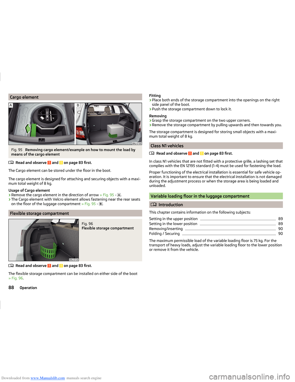
Downloaded from www.Manualslib.com manuals search engine Cargo elementFig. 95
Removing cargo element/example on how to mount the load by
means of the cargo element
Read and observe
and on page 83 first.
The Cargo element can be stored under the floor in the boot.
The cargo element is designed for attaching and securing objects with a maxi-
mum total weight of 8 kg.
Usage of Cargo element
›
Remove the cargo element in the direction of arrow » Fig. 95 -
.
›
The Cargo element with Velcro element allows fastening near the rear seats
on the floor of the luggage compartment » Fig. 95 -
.
Flexible storage compartment
Fig. 96
Flexible storage compartment
Read and observe and on page 83 first.
The flexible storage compartment can be installed on either side of the boot
» Fig. 96 .
Fitting›Place both ends of the storage compartment into the openings on the right
side panel of the boot.›
Push the storage compartment down to lock it.
Removing
›
Grasp the storage compartment on the two upper corners.
›
Remove the storage compartment by pulling upwards and then towards you.
The storage compartment is designed for storing small objects with a maxi-
mum total weight of 8 kg.
Class N1 vehicles
Read and observe
and on page 83 first.
In class N1 vehicles that are not fitted with a protective grille, a lashing set that
complies with the EN 12195 standard (1-4) must be used for fastening the load.
Proper functioning of the electrical installation is essential for safe vehicle op-
eration. It is important to ensure that the electrical installation is not damaged
during the adjustment process or when the storage area is being loaded and
unloaded.
Variable loading floor in the luggage compartment
Introduction
This chapter contains information on the following subjects:
Setting in the upper position
89
Setting in the lower position
89
Removing/inserting
90
Folding / Securing
90
The maximum permissible load of the variable loading floor is 75 kg. For the
transport of heavy loads, adjust the variable loading floor to the lower position
or remove it from the vehicle.
88Operation
Page 94 of 216
Downloaded from www.Manualslib.com manuals search engine Up to two bicycles can be transported in a carrier in the luggage compartment.
Maximum size of the transported bikes: 19 "frame with 26" wheels.
Before transporting, the following steps must be taken.›
Remove the roll-up cover » page 87.
›
Push the head rests into the seat backrests until they click into position
» page 70 .
›
Fold the rear seat forward » page 73.
›
Fold the rear seat backrests forward » page 72.
WARNINGWhen transporting bicycles, ensuring the safety of the passengers is para-
mount.
CAUTION
■ Take care handling the bicycle - there is a risk of damaging the vehicle.■The bike rack cannot be installed if the variable cargo floor is stowed in the
luggage compartment.
Install/remove crossmember
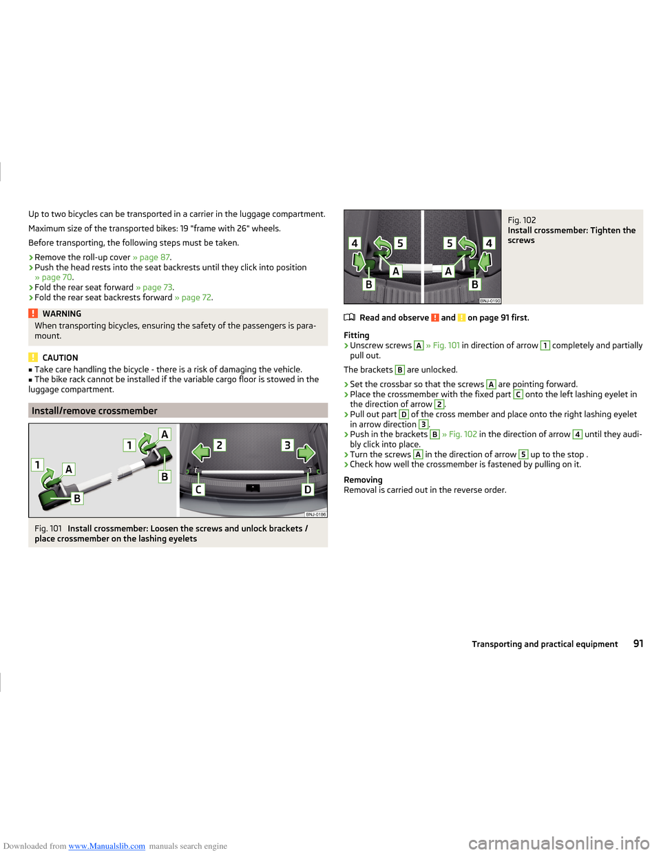
Fig. 101
Install crossmember: Loosen the screws and unlock brackets /
place crossmember on the lashing eyelets
Fig. 102
Install crossmember: Tighten the
screws
Read and observe and on page 91 first.
Fitting
›
Unscrew screws
A
» Fig. 101 in direction of arrow
1
completely and partially
pull out.
The brackets
B
are unlocked.
›
Set the crossbar so that the screws
A
are pointing forward.
›
Place the crossmember with the fixed part
C
onto the left lashing eyelet in
the direction of arrow
2
.
›
Pull out part
D
of the cross member and place onto the right lashing eyelet
in arrow direction
3
.
›
Push in the brackets
B
» Fig. 102 in the direction of arrow
4
until they audi-
bly click into place.
›
Turn the screws
A
in the direction of arrow
5
up to the stop .
›
Check how well the crossmember is fastened by pulling on it.
Removing
Removal is carried out in the reverse order.
91Transporting and practical equipment
Page 98 of 216
Downloaded from www.Manualslib.com manuals search engine WARNING (Continued)■Under certain circumstances, air at a temperature of about 5 °C can flow
out of the vents when the cooling system is switched on.■
To reduce health risks (e.g. common colds), the following instructions for
the use of the cooling system are to be observed. ■The difference between the indoor temperature and the outdoor air
temperature should not be greater than about 5 ° C.
■ The cooling system is to be turned off about 10 minutes before the end
of the journey.
■ Once a year, disinfection of the air conditioner or the Climatronic is to be
carried out by a specialist company.
CAUTION
■ The air inlet in front of the windscreen must be free (e.g. of ice, snow or
leaves) to ensure that the heating and cooling system operates properly.■
After switching on the cooling system condensation from the evaporator of
the air conditioning may drip down and form a puddle below the vehicle. This is
not a leak!
■
If the coolant temperature is too high, the cooling system is switched off to
ensure that the engine cools down.
Note
The used air flows out through the vents in the luggage compartment.
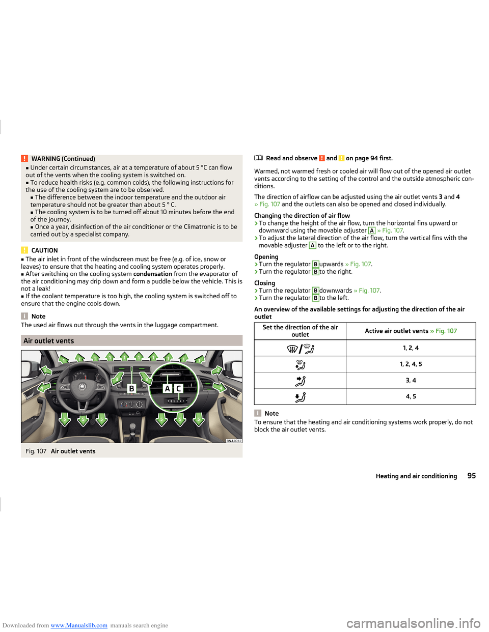
Air outlet vents
Fig. 107
Air outlet vents
Read and observe and on page 94 first.
Warmed, not warmed fresh or cooled air will flow out of the opened air outlet vents according to the setting of the control and the outside atmospheric con-
ditions.
The direction of airflow can be adjusted using the air outlet vents 3 and 4
» Fig. 107 and the outlets can also be opened and closed individually.
Changing the direction of air flow
›
To change the height of the air flow, turn the horizontal fins upward or
downward using the movable adjuster
A
» Fig. 107 .
›
To adjust the lateral direction of the air flow, turn the vertical fins with the
movable adjuster
A
to the left or to the right.
Opening
›
Turn the regulator
B
upwards » Fig. 107 .
›
Turn the regulator
B
to the right.
Closing
›
Turn the regulator
B
downwards » Fig. 107.
›
Turn the regulator
B
to the left.
An overview of the available settings for adjusting the direction of the air
outlet
Set the direction of the air outletActive air outlet vents » Fig. 1071, 2 , 41, 2 , 4 , 53 , 44 , 5
Note
To ensure that the heating and air conditioning systems work properly, do not
block the air outlet vents.95Heating and air conditioning
Page 103 of 216
Downloaded from www.Manualslib.com manuals search engine Driving
Starting-off and driving
Starting and stopping the engine using the key
Introduction
This chapter contains information on the following subjects:
Electronic immobilizer
100
Steering lock locking / unlocking
100
Turn ignition on / off and start the engine
101
Stopping the engine
101
With the key in the ignition, the ignition can be switched on and off and the
engine can be started / stopped.
WARNING■ While driving with the engine stopped, the ignition must always be
switched on » page 101, Turn ignition on / off and start the engine .
■ With the ignition off, the steering may lock » page 100 - danger of an
accident!■
Do not withdraw the ignition key from the ignition lock until the vehicle
has come to a stop » page 107, Parking . Otherwise, the steering may lock -
danger of an accident!
■
Never leave the key in the vehicle when you exit the vehicle. Unauthor-
ized persons such as children could lock the car, turn on the ignition or start
the engine -risk of injury, accidents and damage!
■
Never leave the vehicle unattended with the engine running - risk of acci-
dent, damage or theft!
■
Never switch off the engine before the vehicle has come to a halt – risk of
accident.
WARNING■ Never (e.g. in garages) run the engine in a closed place - risk of poisoning
and death!■
Do not leave any items (e.g. cleaning cloths or tools) in the engine com-
partment. There is a fire hazard and the risk of engine damage.
■
Never cover the engine with additional insulation material (e.g. with a
blanket) – risk of fire.
CAUTION■ Only start the engine when the engine and the vehicle are stationary - risk of
starter and engine damage!■
Do not push-start the engine – there is a risk of damaging the engine and
the catalytic converter. The battery from another vehicle can be used as a
jump-start aid » page 174.
Note
Do not warm up the engine while the vehicle is stationary. If possible, start
your journey as soon as the engine has started. The engine reaches its operat-
ing temperature faster this way.
Electronic immobilizer
Read and observe
and on page 100 first.
The electronic immobilizer makes a possible attempted theft or unauthorizeduse of your vehicle more difficult.
An electronic chip is integrated in the head of the key. The electronic immobil-
iser is deactivated with the aid of this chip when the key is inserted in the igni-
tion lock.
As soon as the ignition key is removed from the ignition lock the immobilizer is
automatically activated.
The engine will not start if an unauthorized ignition key is used.
The following message is shown in the information cluster display. Immobilizer active.
IMMOBILIZER ACTIVE
Steering lock locking / unlocking
Read and observe
and on page 100 first.
The steering lock (steering lock) deters any attempted theft of your vehicle.
Locking
›
Withdraw the ignition key.
›
Turn the steering wheel to the left or right until the steering lock clicks into
place.
Unlocking
›
Insert the key into the ignition lock.
100Driving
Page 104 of 216
Downloaded from www.Manualslib.com manuals search engine ›Switch on the ignition
» page 101.
The steering column lock is unlocked.
If the ignition switch cannot be turned on, turn the steering wheel back and forth slightly to unlock the steering lock.
Turn ignition on / off and start the engine
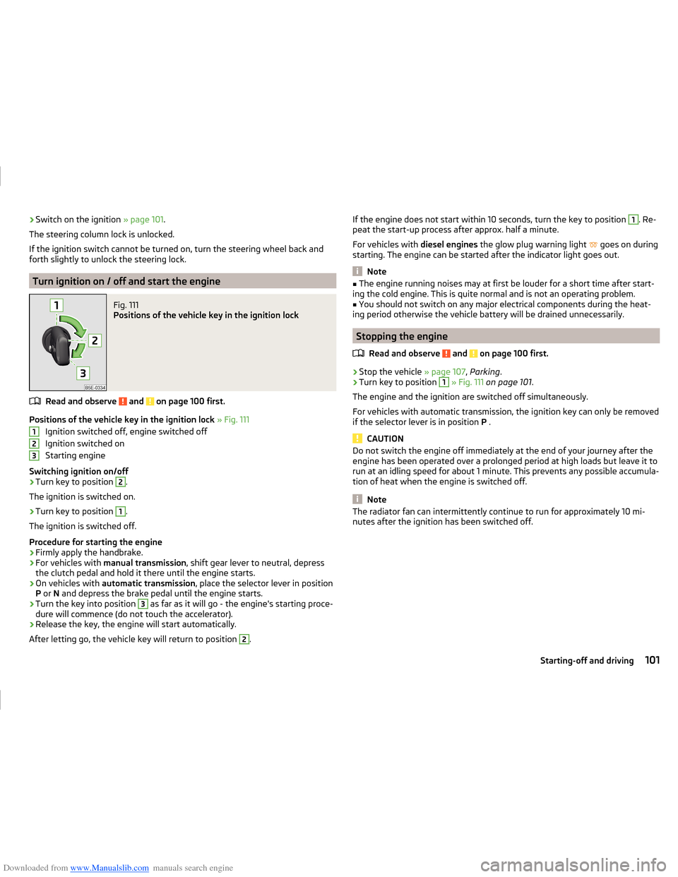
Fig. 111
Positions of the vehicle key in the ignition lock
Read and observe and on page 100 first.
Positions of the vehicle key in the ignition lock » Fig. 111
Ignition switched off, engine switched off
Ignition switched on
Starting engine
Switching ignition on/off
›
Turn key to position
2
.
The ignition is switched on.
›
Turn key to position
1
.
The ignition is switched off.
Procedure for starting the engine
›
Firmly apply the handbrake.
›
For vehicles with manual transmission , shift gear lever to neutral, depress
the clutch pedal and hold it there until the engine starts.
›
On vehicles with automatic transmission , place the selector lever in position
P or N and depress the brake pedal until the engine starts.
›
Turn the key into position
3
as far as it will go - the engine's starting proce-
dure will commence (do not touch the accelerator).
›
Release the key, the engine will start automatically.
After letting go, the vehicle key will return to position
2
.
123If the engine does not start within 10 seconds, turn the key to position 1. Re-
peat the start-up process after approx. half a minute.
For vehicles with diesel engines the glow plug warning light
goes on during
starting. The engine can be started after the indicator light goes out.
Note
■ The engine running noises may at first be louder for a short time after start-
ing the cold engine. This is quite normal and is not an operating problem.■
You should not switch on any major electrical components during the heat-
ing period otherwise the vehicle battery will be drained unnecessarily.
Stopping the engine
Read and observe
and on page 100 first.
›
Stop the vehicle » page 107, Parking .
›
Turn key to position
1
» Fig. 111 on page 101 .
The engine and the ignition are switched off simultaneously.
For vehicles with automatic transmission, the ignition key can only be removed
if the selector lever is in position P .
CAUTION
Do not switch the engine off immediately at the end of your journey after the
engine has been operated over a prolonged period at high loads but leave it to
run at an idling speed for about 1 minute. This prevents any possible accumula-
tion of heat when the engine is switched off.
Note
The radiator fan can intermittently continue to run for approximately 10 mi-
nutes after the ignition has been switched off.101Starting-off and driving
Page 105 of 216
Downloaded from www.Manualslib.com manuals search engine Starting and stopping the engine at the push of the button
Introduction
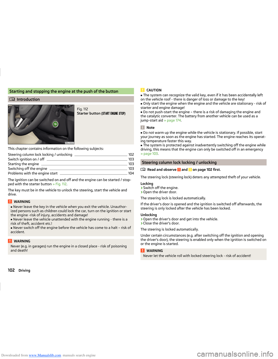
Fig. 112
Starter button (
)
This chapter contains information on the following subjects:
Steering column lock locking / unlocking
102
Switch ignition on / off
103
Starting the engine
103
Switching off the engine
103
Problems with the engine start
104
The ignition can be switched on and off and the engine can be started / stop-
ped with the starter button » Fig. 112.
The key must be in the vehicle to unlock the steering, start the vehicle and
drive.
WARNING■ Never leave the key in the vehicle when you exit the vehicle. Unauthor-
ized persons such as children could lock the car, turn on the ignition or start
the engine -risk of injury, accidents and damage!■
Never leave the vehicle unattended with the engine running - there is a
risk of theft, accident etc.!
■
Never switch off the engine before the vehicle has come to a halt – risk of
accident.
WARNINGNever (e.g. in garages) run the engine in a closed place - risk of poisoning
and death!CAUTION■ The system can recognize the valid key, even if it has been accidentally left
on the vehicle roof - there is danger of loss or damage to the key!■
Only start the engine when the engine and the vehicle are stationary - risk of
starter and engine damage!
■
Do not push-start the engine – there is a risk of damaging the engine and
the catalytic converter. The battery from another vehicle can be used as a
jump-start aid » page 174.
Note
■
Do not warm up the engine while the vehicle is stationary. If possible, start
your journey as soon as the engine has started. The engine reaches its operat-
ing temperature faster this way.■
The system is protected against inadvertently switching off the engine while
driving, this means that the engine can only be switched off in an emergency
» page 103 .
Steering column lock locking / unlocking
Read and observe
and on page 102 first.
The steering lock (steering lock) deters any attempted theft of your vehicle.
Locking
›
Switch off the engine.
›
Open the driver door.
The steering lock is locked automatically.
If the driver's door is opened and the ignition is switched off afterwards, the
steering is only locked after the vehicle has been locked.
Unlocking
›
Open the driver's door and get into the vehicle.
›
Close the driver's door.
The steering is locked automatically.
Under certain circumstances (e.g. after switching off the ignition and opening
the driver's door), the steering is enabled only when the ignition is switched on
or the engine is started.
WARNINGNever let the vehicle roll with locked steering lock - risk of accident!102Driving