fuse box SKODA FABIA 2014 3.G / NJ Operating Instruction Manual
[x] Cancel search | Manufacturer: SKODA, Model Year: 2014, Model line: FABIA, Model: SKODA FABIA 2014 3.G / NJPages: 216, PDF Size: 30.9 MB
Page 29 of 216
Downloaded from www.Manualslib.com manuals search engine Operation
Cockpit
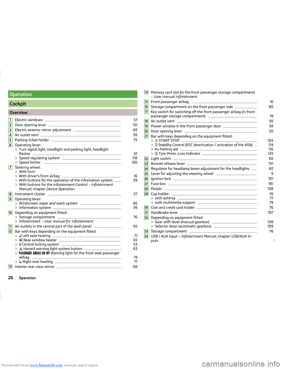
OverviewElectric windows
57
Door opening lever
50
Electric exterior mirror adjustment
69
Air outlet vent
95
Parking ticket holder
75
Operating lever:
› Turn signal light, headlight and parking light, headlight
flasher
61
› Speed regulating system
118
›Speed limiter
120
Steering wheel:
› With horn
› With driver’s front airbag
16
›With buttons for the operation of the information system
39
›With buttons for the Infotainment Control
» Infotainment
Manual , chapter Device Operation
Instrument cluster
27
Operating lever: › Windscreen wiper and wash system
66
›Information system
39
Depending on equipment fitted:
› Storage compartment
76
›Infotainment
» User manual for Infotainment
Air outlets in the central part of the dash panel
95
Bar with keys depending on the equipment fitted: ›
Left seat heating
71
›
Rear window heater
65
›
Central locking system
53
›
Hazard warning light system button
63
›
Warning light for the front seat passenger
airbag
19
›
Right seat heating
71
Interior rear-view mirror
6812345678910111213Memory card slot (in the front passenger storage compartment)
» User manual Infotainment
Front passenger airbag16
Storage compartment on the front passenger side
80
Key switch for switching off the front passenger airbag (in front
passenger storage compartment)
19
Air outlet vent
95
Power window in the front passenger door
58
Door opening lever
50
Bar with keys depending on the equipment fitted:
›
START STOP
104
›
Stability Control (ESC deactivation / activation of the ASR)
114
›
Parking aid
116
›
Tyre Press. Loss Indicator
125
Light switch
60
Bonnet release lever
151
Regulator for headlamp beam adjustment for the headlights
60
Lever for adjusting the steering wheel
9
Ignition lock
101
Fuse box
181
Pedals
108
Cup holder:
76
› with ashtray
77
›with multimedia support
79
Coin and credit card holder
76
Handbrake lever
107
Depending on equipment fitted:
› Gear shift lever (manual gearbox)
108
›Selector lever (automatic gearbox)
109
Storage compartment
76
USB / AUX input
» Infotainment Manual , chapter USB/AUX In-
puts
14151617181920212223242526272829303132333426Operation
Page 39 of 216
Downloaded from www.Manualslib.com manuals search engine Automatic TransmissionRead and observe
on page 32 first.
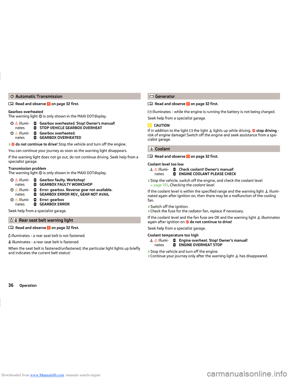
Gearbox overheated
The warning light
is only shown in the MAXI DOTdisplay.
Illumi-
nates
Gearbox overheated. Stop! Owner's manual!
STOP VEHICLE GEARBOX OVERHEAT Illumi-
nates
Gearbox overheated.
GEARBOX OVERHEATED
›
do not continue to drive! Stop the vehicle and turn off the engine.
You can continue your journey as soon as the warning light disappears.
If the warning light does not go out, do not continue driving. Seek help from a specialist garage.
Transmission problem
The warning light is only shown in the MAXI DOTdisplay.
Illumi-
nates
Gearbox faulty. Workshop!
GEARBOX FAULTY WORKSHOP Illumi-
nates
Error: gearbox. Reverse gear not available.
GEARBOX ERROR REV_ GEAR NOT AVAIL Illumi-
nates
Error: gearbox
GEARBOX ERROR
Seek help from a specialist garage.
Rear seat belt warning light
Read and observe
on page 32 first.
illuminates - a rear seat belt is not fastened.
illuminates - a rear seat belt is fastened.
When the seat belt is fastened/unfastened, the particular light lights up briefly
and indicates the current belt status!
Generator
Read and observe
on page 32 first.
illuminates - while the engine is running the battery is not being charged.
Seek help from a specialist garage.
CAUTION
If in addition to the light the light lights up while driving, stop driving -
risk of engine damage! Switch off the engine and seek assistance from a spe-
cialist garage.
Coolant
Read and observe
on page 32 first.
Coolant level too low
Illumi-
nates
Check coolant! Owner's manual!
ENGINE COOLANT PLEASE CHECK
› Stop the vehicle, switch off the engine, and check the coolant level
» page 155 , Checking the coolant level .
If the coolant level is within the specified range and the warning light illumi-
nated again after ignition on, then there may be a malfunction of the cooling
fan.
› Switch off the ignition.
› Check the fuse for the radiator fan, replace if necessary.
If the coolant level and the fan fuse are OK and the warning light illuminates
again after ignition on
do not continue to drive!
Seek help from a specialist garage.
Coolant temperature too high
Illumi-
nates
Engine overheat. Stop! Owner's manual!
ENGINE OVERHEAT STOP
› Stop the vehicle and turn off the engine.
› Continue your journey only after the warning light
has disappeared.
36Operation
Page 113 of 216
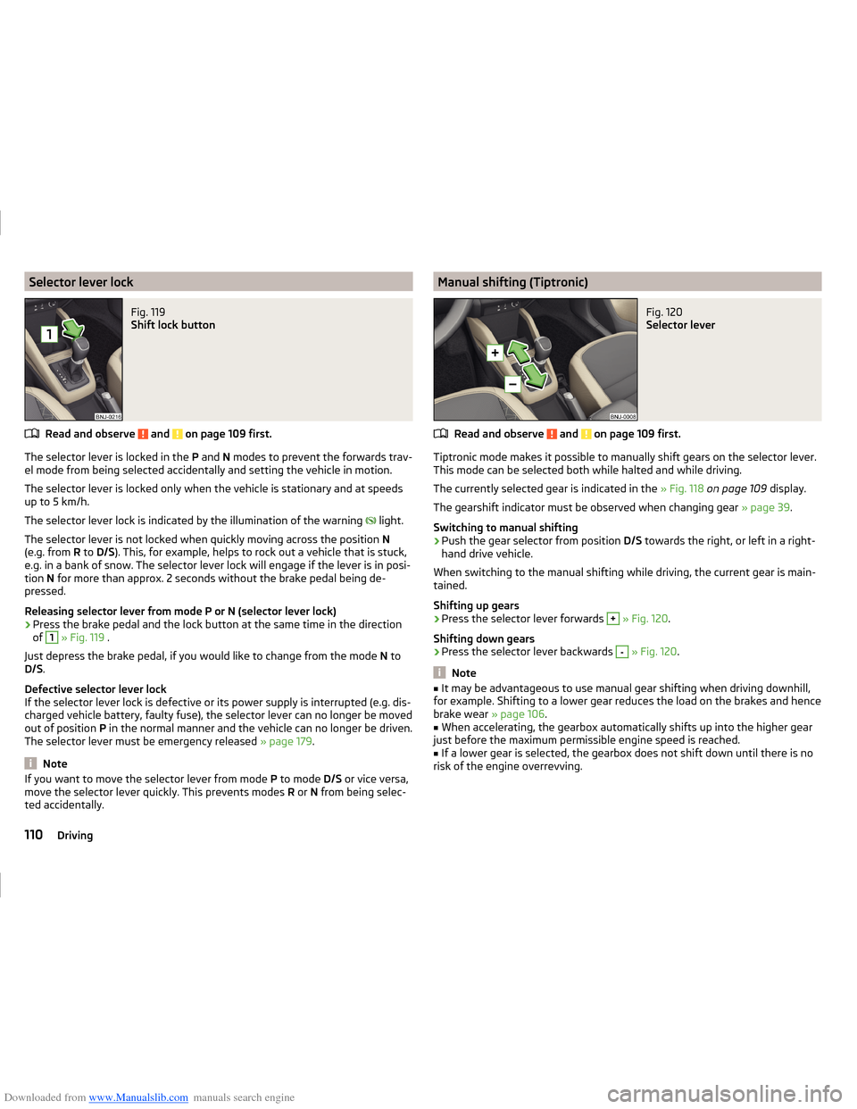
Downloaded from www.Manualslib.com manuals search engine Selector lever lockFig. 119
Shift lock button
Read and observe and on page 109 first.
The selector lever is locked in the P and N modes to prevent the forwards trav-
el mode from being selected accidentally and setting the vehicle in motion.
The selector lever is locked only when the vehicle is stationary and at speeds
up to 5 km/h.
The selector lever lock is indicated by the illumination of the warning light.
The selector lever is not locked when quickly moving across the position N
(e.g. from R to D/S ). This, for example, helps to rock out a vehicle that is stuck,
e.g. in a bank of snow. The selector lever lock will engage if the lever is in posi-
tion N for more than approx. 2 seconds without the brake pedal being de-
pressed.
Releasing selector lever from mode P or N (selector lever lock)
›
Press the brake pedal and the lock button at the same time in the direction
of
1
» Fig. 119 .
Just depress the brake pedal, if you would like to change from the mode N to
D/S .
Defective selector lever lock
If the selector lever lock is defective or its power supply is interrupted (e.g. dis-
charged vehicle battery, faulty fuse), the selector lever can no longer be moved
out of position P in the normal manner and the vehicle can no longer be driven.
The selector lever must be emergency released » page 179.
Note
If you want to move the selector lever from mode P to mode D/S or vice versa,
move the selector lever quickly. This prevents modes R or N from being selec-
ted accidentally.Manual shifting (Tiptronic)Fig. 120
Selector lever
Read and observe and on page 109 first.
Tiptronic mode makes it possible to manually shift gears on the selector lever. This mode can be selected both while halted and while driving.
The currently selected gear is indicated in the » Fig. 118 on page 109 display.
The gearshift indicator must be observed when changing gear » page 39.
Switching to manual shifting
›
Push the gear selector from position D/S towards the right, or left in a right-
hand drive vehicle.
When switching to the manual shifting while driving, the current gear is main-
tained.
Shifting up gears
›
Press the selector lever forwards
+
» Fig. 120 .
Shifting down gears
›
Press the selector lever backwards
-
» Fig. 120 .
Note
■
It may be advantageous to use manual gear shifting when driving downhill,
for example. Shifting to a lower gear reduces the load on the brakes and hence
brake wear » page 106.■
When accelerating, the gearbox automatically shifts up into the higher gear
just before the maximum permissible engine speed is reached.
■
If a lower gear is selected, the gearbox does not shift down until there is no
risk of the engine overrevving.
110Driving
Page 135 of 216
Downloaded from www.Manualslib.com manuals search engine CAUTION■If the operating lever B is held firm and not pushed downwards as far as it
can go, it will go back up after the ball head is removed and will not latch into
the ready position. The ball head then needs to be brought into this position
before the next time it is fitted » page 128, Adjusting the ready position .■
Place the tow bar in the standby position, with the key upwards, and store in
the box - otherwise there is a risk of damage to the key!
■
Do not use excessive force when handling the operating lever (e.g. do not
step on it).
Note
Clean any dirt from the ball head before stowing it away in the box with the
vehicle tool kit.
Accessories
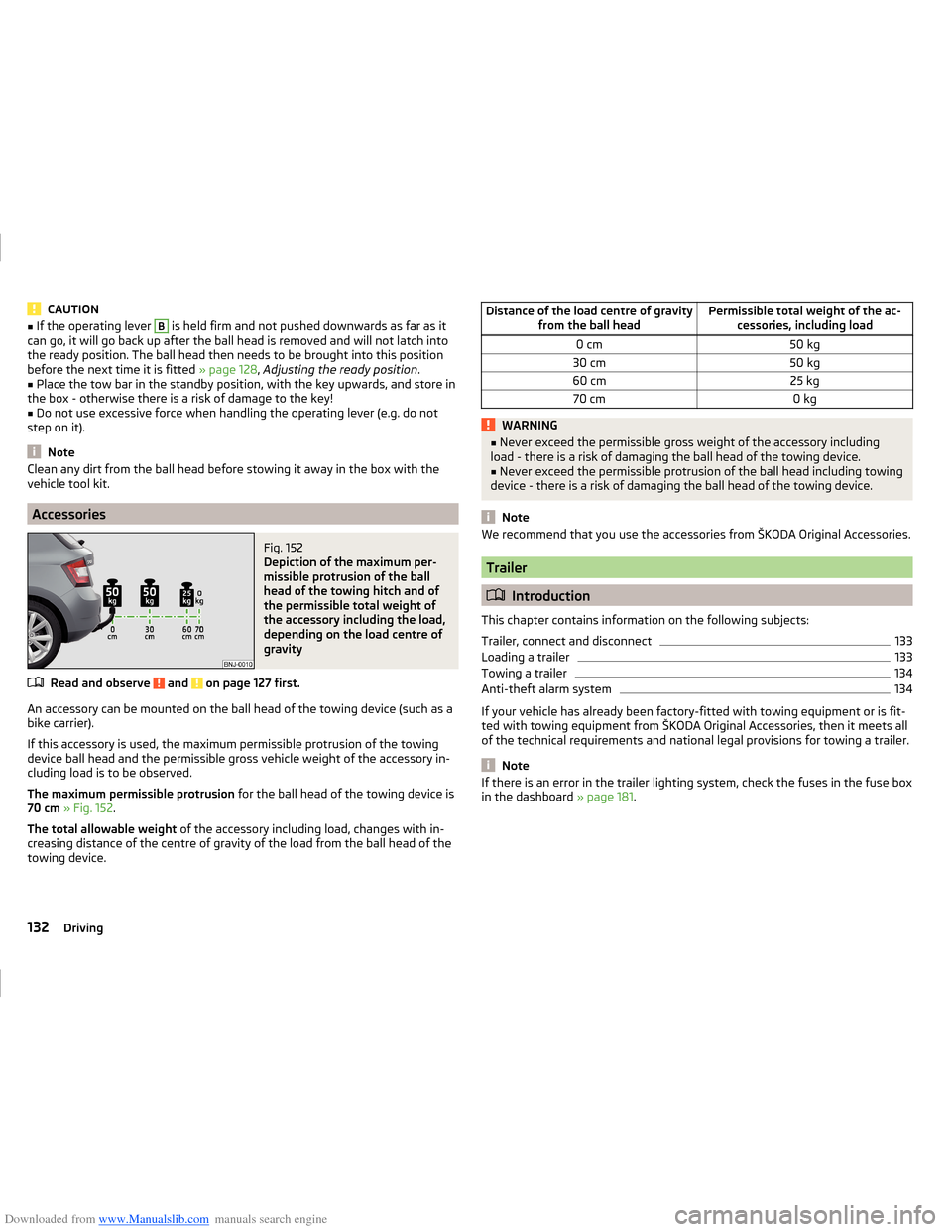
Fig. 152
Depiction of the maximum per-
missible protrusion of the ball
head of the towing hitch and of
the permissible total weight of
the accessory including the load,
depending on the load centre of
gravity
Read and observe and on page 127 first.
An accessory can be mounted on the ball head of the towing device (such as a
bike carrier).
If this accessory is used, the maximum permissible protrusion of the towing
device ball head and the permissible gross vehicle weight of the accessory in-
cluding load is to be observed.
The maximum permissible protrusion for the ball head of the towing device is
70 cm » Fig. 152 .
The total allowable weight of the accessory including load, changes with in-
creasing distance of the centre of gravity of the load from the ball head of the
towing device.
Distance of the load centre of gravity from the ball headPermissible total weight of the ac-cessories, including load0 cm50 kg30 cm50 kg60 cm25 kg70 cm0 kgWARNING■Never exceed the permissible gross weight of the accessory including
load - there is a risk of damaging the ball head of the towing device.■
Never exceed the permissible protrusion of the ball head including towing
device - there is a risk of damaging the ball head of the towing device.
Note
We recommend that you use the accessories from ŠKODA Original Accessories.
Trailer
Introduction
This chapter contains information on the following subjects:
Trailer, connect and disconnect
133
Loading a trailer
133
Towing a trailer
134
Anti-theft alarm system
134
If your vehicle has already been factory-fitted with towing equipment or is fit-
ted with towing equipment from ŠKODA Original Accessories, then it meets all
of the technical requirements and national legal provisions for towing a trailer.
Note
If there is an error in the trailer lighting system, check the fuses in the fuse box
in the dashboard » page 181.132Driving
Page 184 of 216
Downloaded from www.Manualslib.com manuals search engine Fuses and light bulbs
Fuses
Introduction
This chapter contains information on the following subjects:
Fuses in the dash panel
181
Assignment of the fuses in the dash panel
182
Fuses in the engine compartment
183
Fuse assignment in the engine compartment
183
Individual electrical circuits are protected by fuses.
Switch off the ignition and the corresponding power consuming device before
replacing a fuse.
Find out which fuse belongs to the component that is not operating
» page 181 , Fuses in the dash panel or » page 183 , Fuses in the engine com-
partment .
Fuse colourMaximum amperagelight brown5dark brown7.5red10blue15yellow/blue20white25green/pink30green40red50WARNINGAlways read and observe the warnings before completing any work in the
engine compartment » page 149.CAUTION■
“Never repair” fuses or replace them with a fuse of a higher amperage – risk
of fire. This may also cause damage at another part of the electrical system.■
A blown fuse is recognisable by the molten metal strip. Replace the faulty
fuse with a new one of the same amperage.
■
If a new fuse burns through again, consult a specialist immediately.
Note
■
We recommend that you always carry replacement fuses in the vehicle. A box
of replacement fuses can be purchased from ŠKODA Original Accessories.■
One fuse may cover several consumers.
■
A single consumer may use several fuses.
Fuses in the dash panel
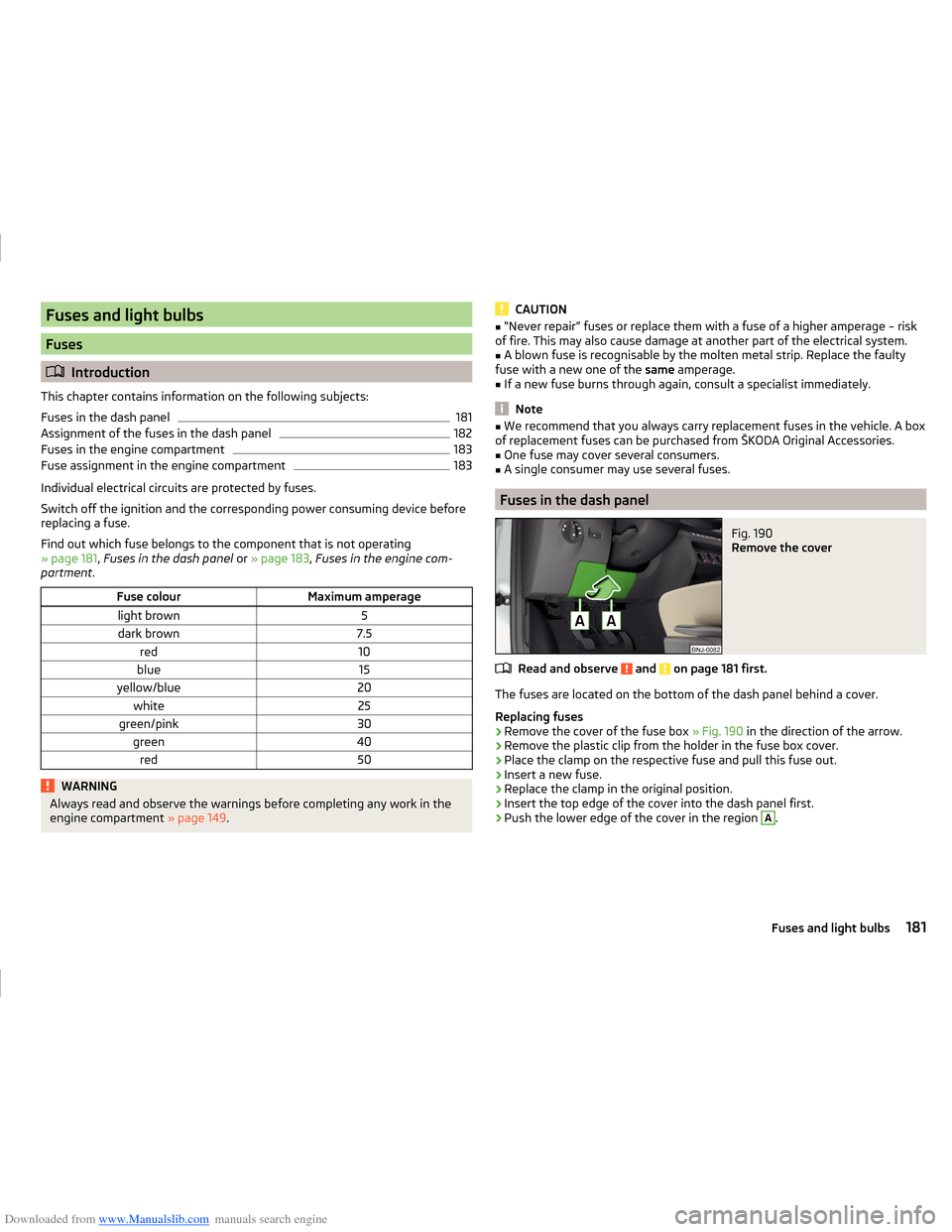
Fig. 190
Remove the cover
Read and observe and on page 181 first.
The fuses are located on the bottom of the dash panel behind a cover.
Replacing fuses
›
Remove the cover of the fuse box » Fig. 190 in the direction of the arrow.
›
Remove the plastic clip from the holder in the fuse box cover.
›
Place the clamp on the respective fuse and pull this fuse out.
›
Insert a new fuse.
›
Replace the clamp in the original position.
›
Insert the top edge of the cover into the dash panel first.
›
Push the lower edge of the cover in the region
A
.
181Fuses and light bulbs
Page 185 of 216
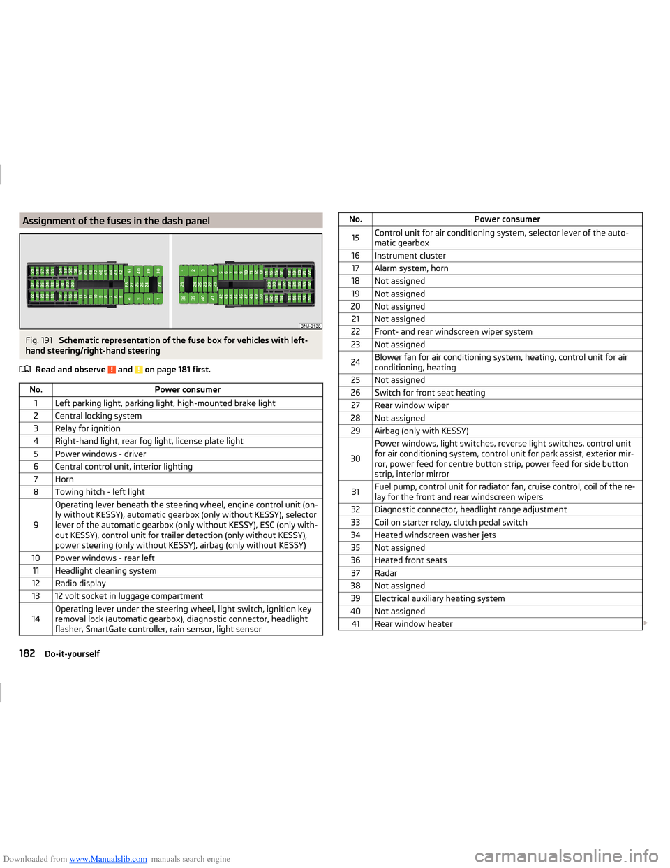
Downloaded from www.Manualslib.com manuals search engine Assignment of the fuses in the dash panelFig. 191
Schematic representation of the fuse box for vehicles with left-
hand steering/right-hand steering
Read and observe
and on page 181 first.
No.Power consumer1Left parking light, parking light, high-mounted brake light2Central locking system3Relay for ignition4Right-hand light, rear fog light, license plate light5Power windows - driver6Central control unit, interior lighting7Horn8Towing hitch - left light
9
Operating lever beneath the steering wheel, engine control unit (on-
ly without KESSY), automatic gearbox (only without KESSY), selector
lever of the automatic gearbox (only without KESSY), ESC (only with-
out KESSY), control unit for trailer detection (only without KESSY),
power steering (only without KESSY), airbag (only without KESSY)10Power windows - rear left11Headlight cleaning system12Radio display1312 volt socket in luggage compartment14Operating lever under the steering wheel, light switch, ignition key
removal lock (automatic gearbox), diagnostic connector, headlight
flasher, SmartGate controller, rain sensor, light sensorNo.Power consumer15Control unit for air conditioning system, selector lever of the auto-
matic gearbox16Instrument cluster17Alarm system, horn18Not assigned19Not assigned20Not assigned21Not assigned22Front- and rear windscreen wiper system23Not assigned24Blower fan for air conditioning system, heating, control unit for air
conditioning, heating25Not assigned26Switch for front seat heating27Rear window wiper28Not assigned29Airbag (only with KESSY)
30
Power windows, light switches, reverse light switches, control unit
for air conditioning system, control unit for park assist, exterior mir-
ror, power feed for centre button strip, power feed for side button
strip, interior mirror31Fuel pump, control unit for radiator fan, cruise control, coil of the re-
lay for the front and rear windscreen wipers32Diagnostic connector, headlight range adjustment33Coil on starter relay, clutch pedal switch34Heated windscreen washer jets35Not assigned36Heated front seats37Radar38Not assigned39Electrical auxiliary heating system40Not assigned41Rear window heater 182Do-it-yourself
Page 186 of 216
Downloaded from www.Manualslib.com manuals search engine No.Power consumer42Power windows - front passenger43Towing hitch - contact in the socket44Cigarette lighter, 12-volt power socket45Power windows - rear right46Front and rear window washer, operating lever under the steering
wheel47Towing hitch - contact in the socket48Towing hitch - right light49Control unit for fuel pump50Radio51Heating of the external mirror52KESSY control unit53KESSY steering lock54Not assigned55Heated front seats56Not assigned57Not assigned58Not assigned59Not assigned
Fuses in the engine compartment
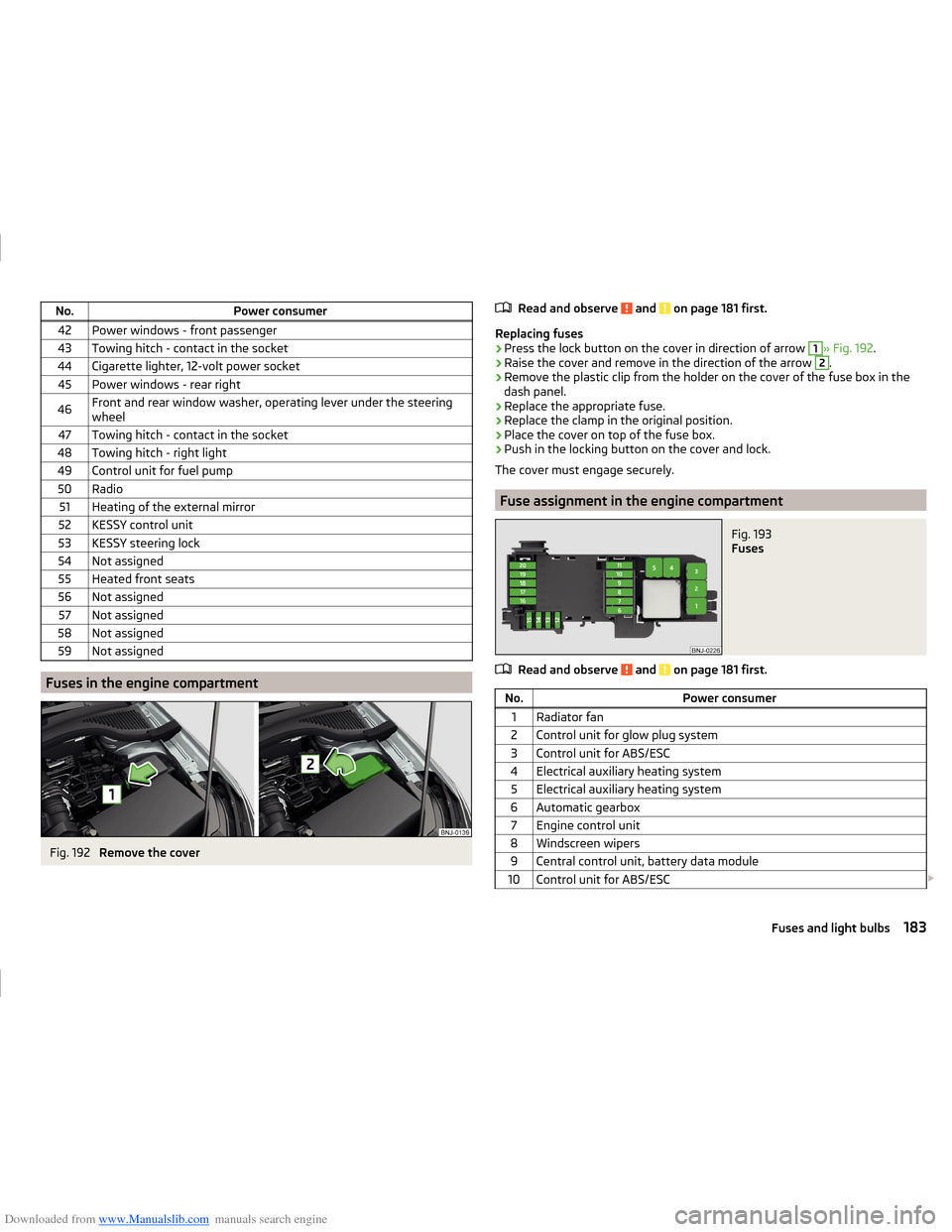
Fig. 192
Remove the cover
Read and observe and on page 181 first.
Replacing fuses
›
Press the lock button on the cover in direction of arrow
1
» Fig. 192 .
›
Raise the cover and remove in the direction of the arrow
2
.
›
Remove the plastic clip from the holder on the cover of the fuse box in the
dash panel.
›
Replace the appropriate fuse.
›
Replace the clamp in the original position.
›
Place the cover on top of the fuse box.
›
Push in the locking button on the cover and lock.
The cover must engage securely.
Fuse assignment in the engine compartment
Fig. 193
Fuses
Read and observe and on page 181 first.
No.Power consumer1Radiator fan2Control unit for glow plug system3Control unit for ABS/ESC4Electrical auxiliary heating system5Electrical auxiliary heating system6Automatic gearbox7Engine control unit8Windscreen wipers9Central control unit, battery data module10Control unit for ABS/ESC 183Fuses and light bulbs