gearbox SKODA FABIA 2014 3.G / NJ Operating Instruction Manual
[x] Cancel search | Manufacturer: SKODA, Model Year: 2014, Model line: FABIA, Model: SKODA FABIA 2014 3.G / NJPages: 216, PDF Size: 30.9 MB
Page 10 of 216
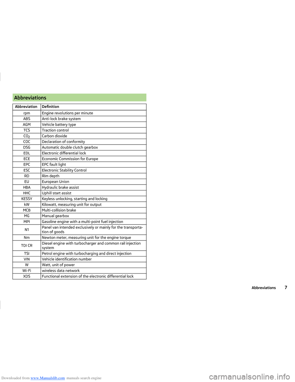
Downloaded from www.Manualslib.com manuals search engine AbbreviationsAbbreviationDefinitionrpmEngine revolutions per minuteABSAnti-lock brake systemAGMVehicle battery typeTCSTraction controlCO2Carbon dioxideCOCDeclaration of conformityDSGAutomatic double clutch gearboxEDLElectronic differential lockECEEconomic Commission for EuropeEPCEPC fault lightESCElectronic Stability ControlRDRim depthEUEuropean UnionHBAHydraulic brake assistHHCUphill start assistKESSYKeyless unlocking, starting and lockingkWKilowatt, measuring unit for outputMCBMulti-collision brakeMGManual gearboxMPIGasoline engine with a multi-point fuel injectionN1Panel van intended exclusively or mainly for the transporta-
tion of goodsNmNewton meter, measuring unit for the engine torqueTDI CRDiesel engine with turbocharger and common rail injection
systemTSIPetrol engine with turbocharging and direct injectionVINVehicle identification numberWWatt, unit of powerWi-Fiwireless data networkXDSFunctional extension of the electronic differential lock7Abbreviations
Page 29 of 216
Downloaded from www.Manualslib.com manuals search engine Operation
Cockpit
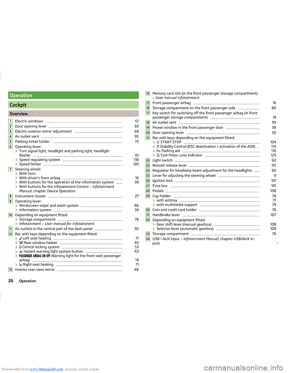
OverviewElectric windows
57
Door opening lever
50
Electric exterior mirror adjustment
69
Air outlet vent
95
Parking ticket holder
75
Operating lever:
› Turn signal light, headlight and parking light, headlight
flasher
61
› Speed regulating system
118
›Speed limiter
120
Steering wheel:
› With horn
› With driver’s front airbag
16
›With buttons for the operation of the information system
39
›With buttons for the Infotainment Control
» Infotainment
Manual , chapter Device Operation
Instrument cluster
27
Operating lever: › Windscreen wiper and wash system
66
›Information system
39
Depending on equipment fitted:
› Storage compartment
76
›Infotainment
» User manual for Infotainment
Air outlets in the central part of the dash panel
95
Bar with keys depending on the equipment fitted: ›
Left seat heating
71
›
Rear window heater
65
›
Central locking system
53
›
Hazard warning light system button
63
›
Warning light for the front seat passenger
airbag
19
›
Right seat heating
71
Interior rear-view mirror
6812345678910111213Memory card slot (in the front passenger storage compartment)
» User manual Infotainment
Front passenger airbag16
Storage compartment on the front passenger side
80
Key switch for switching off the front passenger airbag (in front
passenger storage compartment)
19
Air outlet vent
95
Power window in the front passenger door
58
Door opening lever
50
Bar with keys depending on the equipment fitted:
›
START STOP
104
›
Stability Control (ESC deactivation / activation of the ASR)
114
›
Parking aid
116
›
Tyre Press. Loss Indicator
125
Light switch
60
Bonnet release lever
151
Regulator for headlamp beam adjustment for the headlights
60
Lever for adjusting the steering wheel
9
Ignition lock
101
Fuse box
181
Pedals
108
Cup holder:
76
› with ashtray
77
›with multimedia support
79
Coin and credit card holder
76
Handbrake lever
107
Depending on equipment fitted:
› Gear shift lever (manual gearbox)
108
›Selector lever (automatic gearbox)
109
Storage compartment
76
USB / AUX input
» Infotainment Manual , chapter USB/AUX In-
puts
14151617181920212223242526272829303132333426Operation
Page 31 of 216
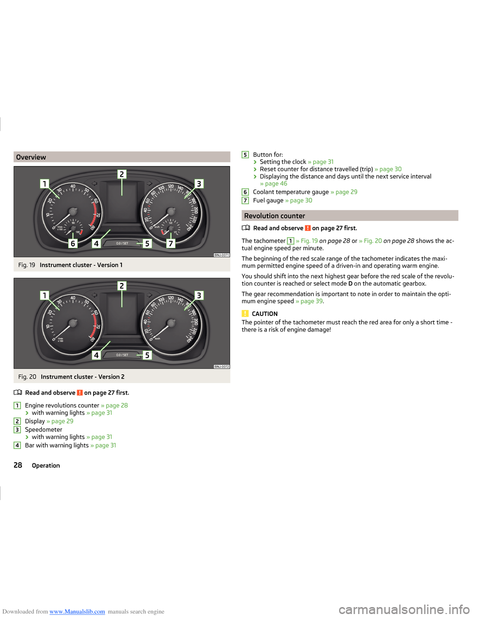
Downloaded from www.Manualslib.com manuals search engine OverviewFig. 19
Instrument cluster - Version 1
Fig. 20
Instrument cluster - Version 2
Read and observe
on page 27 first.
Engine revolutions counter » page 28
› with warning lights
» page 31
Display » page 29
Speedometer › with warning lights
» page 31
Bar with warning lights » page 31
1234Button for:
› Setting the clock
» page 31
› Reset counter for distance travelled (trip)
» page 30
› Displaying the distance and days until the next service interval
» page 46
Coolant temperature gauge » page 29
Fuel gauge » page 30
Revolution counter
Read and observe
on page 27 first.
The tachometer
1
» Fig. 19 on page 28 or » Fig. 20 on page 28 shows the ac-
tual engine speed per minute.
The beginning of the red scale range of the tachometer indicates the maxi-
mum permitted engine speed of a driven-in and operating warm engine.
You should shift into the next highest gear before the red scale of the revolu- tion counter is reached or select mode D on the automatic gearbox.
The gear recommendation is important to note in order to maintain the opti-
mum engine speed » page 39.
CAUTION
The pointer of the tachometer must reach the red area for only a short time -
there is a risk of engine damage!56728Operation
Page 39 of 216
Downloaded from www.Manualslib.com manuals search engine Automatic TransmissionRead and observe
on page 32 first.
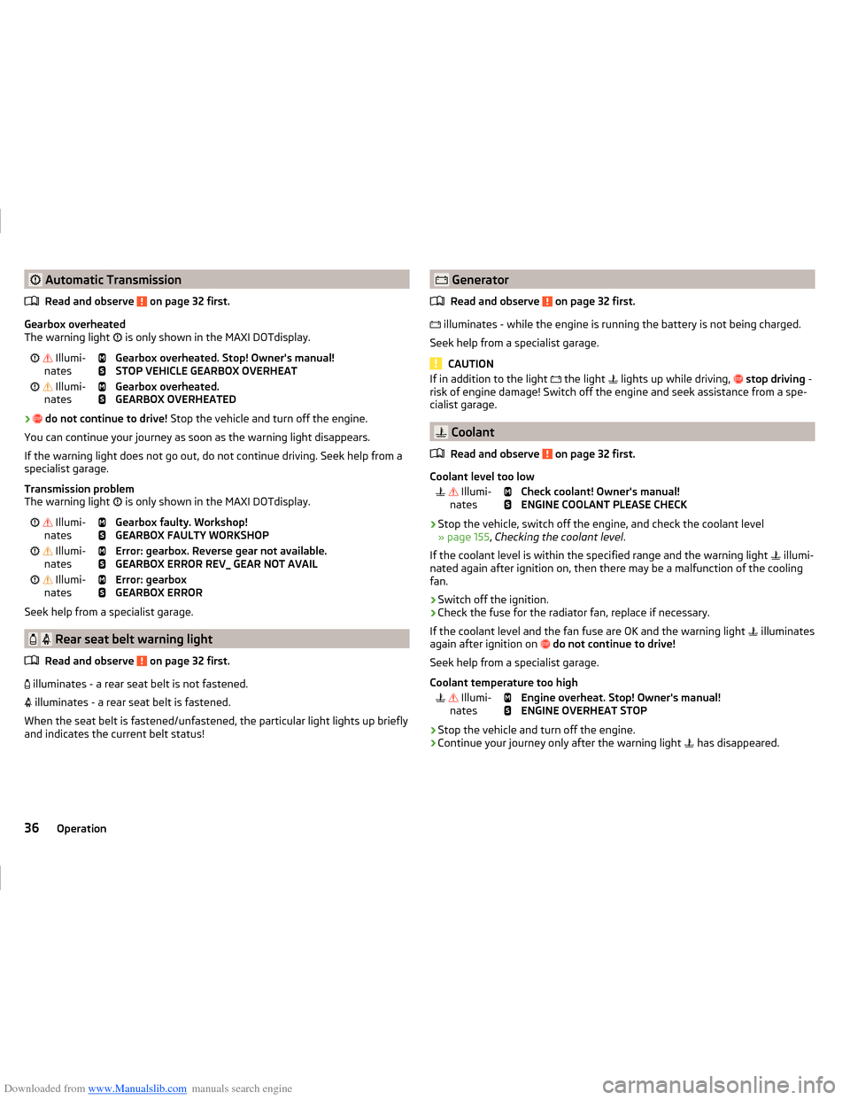
Gearbox overheated
The warning light
is only shown in the MAXI DOTdisplay.
Illumi-
nates
Gearbox overheated. Stop! Owner's manual!
STOP VEHICLE GEARBOX OVERHEAT Illumi-
nates
Gearbox overheated.
GEARBOX OVERHEATED
›
do not continue to drive! Stop the vehicle and turn off the engine.
You can continue your journey as soon as the warning light disappears.
If the warning light does not go out, do not continue driving. Seek help from a specialist garage.
Transmission problem
The warning light is only shown in the MAXI DOTdisplay.
Illumi-
nates
Gearbox faulty. Workshop!
GEARBOX FAULTY WORKSHOP Illumi-
nates
Error: gearbox. Reverse gear not available.
GEARBOX ERROR REV_ GEAR NOT AVAIL Illumi-
nates
Error: gearbox
GEARBOX ERROR
Seek help from a specialist garage.
Rear seat belt warning light
Read and observe
on page 32 first.
illuminates - a rear seat belt is not fastened.
illuminates - a rear seat belt is fastened.
When the seat belt is fastened/unfastened, the particular light lights up briefly
and indicates the current belt status!
Generator
Read and observe
on page 32 first.
illuminates - while the engine is running the battery is not being charged.
Seek help from a specialist garage.
CAUTION
If in addition to the light the light lights up while driving, stop driving -
risk of engine damage! Switch off the engine and seek assistance from a spe-
cialist garage.
Coolant
Read and observe
on page 32 first.
Coolant level too low
Illumi-
nates
Check coolant! Owner's manual!
ENGINE COOLANT PLEASE CHECK
› Stop the vehicle, switch off the engine, and check the coolant level
» page 155 , Checking the coolant level .
If the coolant level is within the specified range and the warning light illumi-
nated again after ignition on, then there may be a malfunction of the cooling
fan.
› Switch off the ignition.
› Check the fuse for the radiator fan, replace if necessary.
If the coolant level and the fan fuse are OK and the warning light illuminates
again after ignition on
do not continue to drive!
Seek help from a specialist garage.
Coolant temperature too high
Illumi-
nates
Engine overheat. Stop! Owner's manual!
ENGINE OVERHEAT STOP
› Stop the vehicle and turn off the engine.
› Continue your journey only after the warning light
has disappeared.
36Operation
Page 54 of 216
Downloaded from www.Manualslib.com manuals search engine Fig. 36
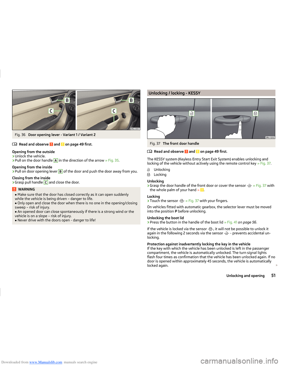
Door opening lever - Variant 1 / Variant 2
Read and observe
and on page 49 first.
Opening from the outside
›
Unlock the vehicle.
›
Pull on the door handle
A
in the direction of the arrow » Fig. 35.
Opening from the inside
›
Pull on door opening lever
B
of the door and push the door away from you.
Closing from the inside
›
Grasp pull handle
C
and close the door.
WARNING■ Make sure that the door has closed correctly as it can open suddenly
while the vehicle is being driven – danger to life.■
Only open and close the door when there is no one in the opening/closing
sweep – risk of injury.
■
An opened door can close spontaneously if there is a strong wind or the
vehicle is on a slope – risk of injury.
■
Never drive with the doors open - danger to life!
Unlocking / locking - KESSYFig. 37
The front door handle
Read and observe
and on page 49 first.
The KESSY system (Keyless Entry Start Exit System) enables unlocking and
locking of the vehicle without actively using the remote control key » Fig. 37.
Unlocking
Locking
Unlocking
›
Grasp the door handle of the front door or cover the sensor
- -
» Fig. 37 with
the whole palm of your hand » .
Locking
›
Touch the sensor
- -
» Fig. 37 with your fingers.
On vehicles fitted with automatic gearbox, the selector lever must be moved
into the position P before unlocking.
Unlocking the boot lid
›
Press the button in the handle of the boot lid » Fig. 41 on page 56 .
If the vehicle is locked via the sensor
- -
, it will not be possible to unlock it
again in the following 2 seconds via the sensor
- -
- prevents accidental un-
locking.
Protection against inadvertently locking the key in the vehicle
If the key with which the vehicle has been unlocked is left in the passenger
compartment, the vehicle is automatically unlocked. The turn signal lights
flash four times as confirmation that the vehicle has been unlocked again. If no
door is opened within approximately 45 seconds, the vehicle is automatically
locked again.
51Unlocking and opening
Page 112 of 216

Downloaded from www.Manualslib.com manuals search engine WARNING■Never accelerate when the mode for moving forward is set with the se-
lector lever - there is a risk of accident!■
Never shift the selector lever to R or P modes when driving – there is a
risk of an accident.
■
If the vehicle is in the mode selected D, S , R or Tiptronic and the engine
stops when at idle speed, then the brake pedal must be pressed. Even
when the engine is idling, power transmission is never completely interrup-
ted – the vehicle will creep.
■
When leaving the vehicle, the selector lever is always to be put in the P
mode. Otherwise the vehicle could then start to move and potentially cause
an accident.
CAUTION
■ If the selector lever is moved to mode N while driving, the accelerator pedal
must be released and you will need to wait until the engine has reached its
idling speed before moving the selector lever to a forward driving mode again.■
When the outdoor temperature is below -10 ° C, the selector lever, when
starting, must always be in P mode.
■
When stopping on a slope, never try to keep the vehicle in position by using
the accelerator pedal – this may lead to gear damage.
Note
After the ignition is switched off, the ignition key can only be withdrawn if the
selector lever is in the position P.
Modes and use of selector lever
Fig. 118
Selector lever/display
Read and observe and on page 109 first.
When the ignition is switched on, the gearbox mode and the currently selected
gear are indicated in the display » Fig. 118.
The following modes can be selected with the selector lever » Fig. 118.
P
– Parking mode
The driven wheels are locked mechanically in this mode.
Parking mode must only be selected when the vehicle is stationary.
R
- Reverse gear
Reverse gear can only be engaged when the vehicle is stationary and the en-
gine is at idling speed.
N
- Neutral
Power transmission to the drive wheels is interrupted in this mode.
D
/
S
- mode for driving forward (Normal program) / mode for driving
forward (Sport program)
The system switches from one mode to the other by moving the selector lever
into the spring-loaded position
» Fig. 118 .
In mode D or S, the forward gears are shifted automatically depending on the
engine load, the operation of the accelerator pedal, the vehicle speed, and the
selected driving mode .
In mode S, the forward gears are shifted automatically up and down at higher
engine speeds than in mode D.
109Starting-off and driving
Page 113 of 216
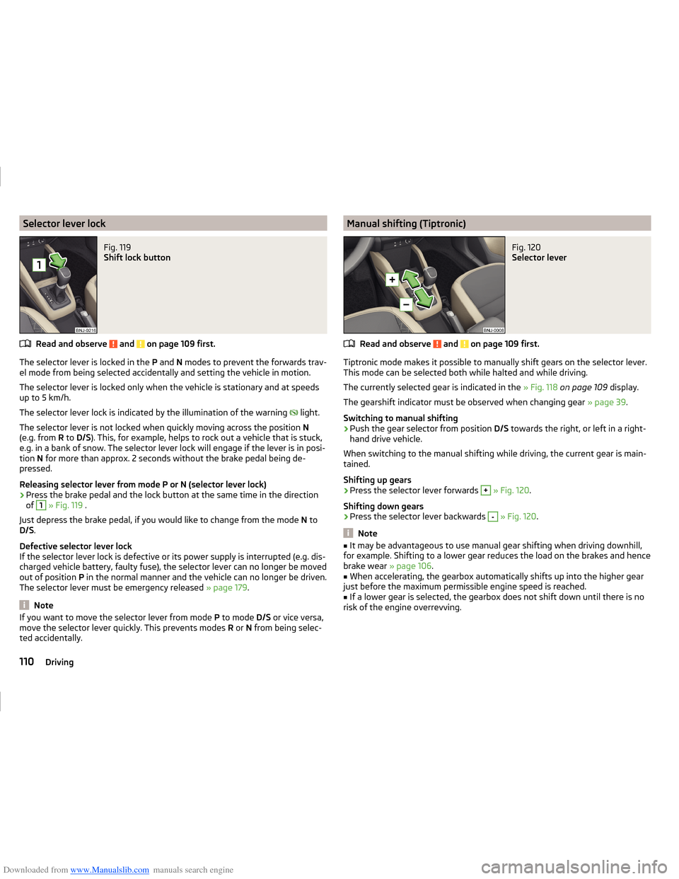
Downloaded from www.Manualslib.com manuals search engine Selector lever lockFig. 119
Shift lock button
Read and observe and on page 109 first.
The selector lever is locked in the P and N modes to prevent the forwards trav-
el mode from being selected accidentally and setting the vehicle in motion.
The selector lever is locked only when the vehicle is stationary and at speeds
up to 5 km/h.
The selector lever lock is indicated by the illumination of the warning light.
The selector lever is not locked when quickly moving across the position N
(e.g. from R to D/S ). This, for example, helps to rock out a vehicle that is stuck,
e.g. in a bank of snow. The selector lever lock will engage if the lever is in posi-
tion N for more than approx. 2 seconds without the brake pedal being de-
pressed.
Releasing selector lever from mode P or N (selector lever lock)
›
Press the brake pedal and the lock button at the same time in the direction
of
1
» Fig. 119 .
Just depress the brake pedal, if you would like to change from the mode N to
D/S .
Defective selector lever lock
If the selector lever lock is defective or its power supply is interrupted (e.g. dis-
charged vehicle battery, faulty fuse), the selector lever can no longer be moved
out of position P in the normal manner and the vehicle can no longer be driven.
The selector lever must be emergency released » page 179.
Note
If you want to move the selector lever from mode P to mode D/S or vice versa,
move the selector lever quickly. This prevents modes R or N from being selec-
ted accidentally.Manual shifting (Tiptronic)Fig. 120
Selector lever
Read and observe and on page 109 first.
Tiptronic mode makes it possible to manually shift gears on the selector lever. This mode can be selected both while halted and while driving.
The currently selected gear is indicated in the » Fig. 118 on page 109 display.
The gearshift indicator must be observed when changing gear » page 39.
Switching to manual shifting
›
Push the gear selector from position D/S towards the right, or left in a right-
hand drive vehicle.
When switching to the manual shifting while driving, the current gear is main-
tained.
Shifting up gears
›
Press the selector lever forwards
+
» Fig. 120 .
Shifting down gears
›
Press the selector lever backwards
-
» Fig. 120 .
Note
■
It may be advantageous to use manual gear shifting when driving downhill,
for example. Shifting to a lower gear reduces the load on the brakes and hence
brake wear » page 106.■
When accelerating, the gearbox automatically shifts up into the higher gear
just before the maximum permissible engine speed is reached.
■
If a lower gear is selected, the gearbox does not shift down until there is no
risk of the engine overrevving.
110Driving
Page 114 of 216
Downloaded from www.Manualslib.com manuals search engine Starting-off and drivingRead and observe
and on page 109 first.
Starting off
›
Start the engine.
›
Firmly depress and hold the brake pedal.
›
Press the lock button in the direction of
1
» Fig. 119 on page 110 and hold.
›
Move the selector lever into the desired position » page 109and then release
the lock button.
›
Release the brake pedal and accelerate.
Stopping (while the car is moving)
›
Fully depress and hold the brake pedal and bring the vehicle to a stop.
›
Keep holding the brake pedal until driving is resumed.
The selector lever position N does not have to be selected when stopping for a
short time, such as at a cross roads.
Kickdown
The kickdown function allows you to achieve maximum acceleration by your vehicle while driving.
When the accelerator pedal is fully depressed, the kickdown function is activa-
ted in any forward driving mode.
The gearbox shifts down one or more gears depending on the vehicle speed
and engine speed, and the vehicle accelerates.
The gearbox does not shift up into the highest gear until the engine has
reached its maximum revolutions for this gear range.
WARNINGRapid acceleration, particularly on slippery roads, can lead to loss of control
of the vehicle – there is a risk of an accident.
Running-in and economical driving
Introduction
This chapter contains information on the following subjects:
Running-in
111
Tips for economical driving
111
DriveGreen function
112The fuel consumption, degree of pollution and vehicle wear depend on driving
style, road condition, weather conditions and the like.
Running-in
Driving in the engine
The engine has to be run in during the first 1 500 kilometres. During this peri-
od, the driving style decides on the quality of the driving-in process.
During the first 1,000 km ,we recommend not driving faster than 3/4 of the
maximum permissible engine speed, not to drive at full throttle and not to use
a trailer.
In the range of 1,000 to 1,500 kilometres, the engine load can be increased up
to the maximum permitted engine speed.
New tyres
New tyres have to be “run in” since they do not offer optimal grip at first.
Drive especially carefully for the first 500 km or so.
New brake pads
New brake pads have to first “grind in” because these do not initially have the
best possible braking effect.
Drive especially carefully for the first 200 km or so.
Tips for economical driving
To achieve the lowest possible fuel consumption, the following instructions
must be observed.
Looking ahead when driving
Avoid unnecessary acceleration and braking.
Change gear in an energy saving and timely manner
Observe the recommended gear » page 39.
Avoid full throttle and high speeds
Fuel consumption can be reduced by half if only three-quarters of the possible
top speed of your vehicle is used.
111Starting-off and driving
Page 171 of 216
Downloaded from www.Manualslib.com manuals search engine CAUTION■Screw the jack back to the starting position before storing in the box with
the tool kit screws.■
Ensure that the vehicle tool kit is safely secured in the boot.
■
Ensure that the box is always secured with the strap.
Note
The declaration of conformity is included with the jack or the log folder.
Changing a wheel
Introduction
This chapter contains information on the following subjects:
Preparation
168
Remove / store wheel
168
Full wheel trim
168
Wheel bolts
169
Anti-theft wheel bolts
169
Loosening/tightening wheel bolts
170
Raising the vehicle
170
Remove the wheel / fix
171
Subsequent steps
171
For your own safety and the safety of the passengers, the following instruc-
tions must be observed before changing a wheel on the road.
Switch on the hazard lights.
The warning triangle must be set up at the prescribed distance - observe
the national legal provisions when doing so.
Park the vehicle as far away as possible from the flow of traffic.
Choose a location with a flat, solid surface.
Have all the occupants get out. The passengers should not stand on the
road (instead they should remain behind a crash barrier, for instance) while
the wheel is being changed.
The national legal requirements must be observed when changing a wheel.
Preparation
Before changing the wheel, the following work should be carried out.
› Switch off the engine.›Select the
first gear or move the selector lever for the automatic gearbox
into position P .›
Apply the handbrake firmly.
›
Uncouple trailer, if attached.
›
Remove the vehicle tool kit » page 167 and the spare wheel from the boot.
Remove / store wheel
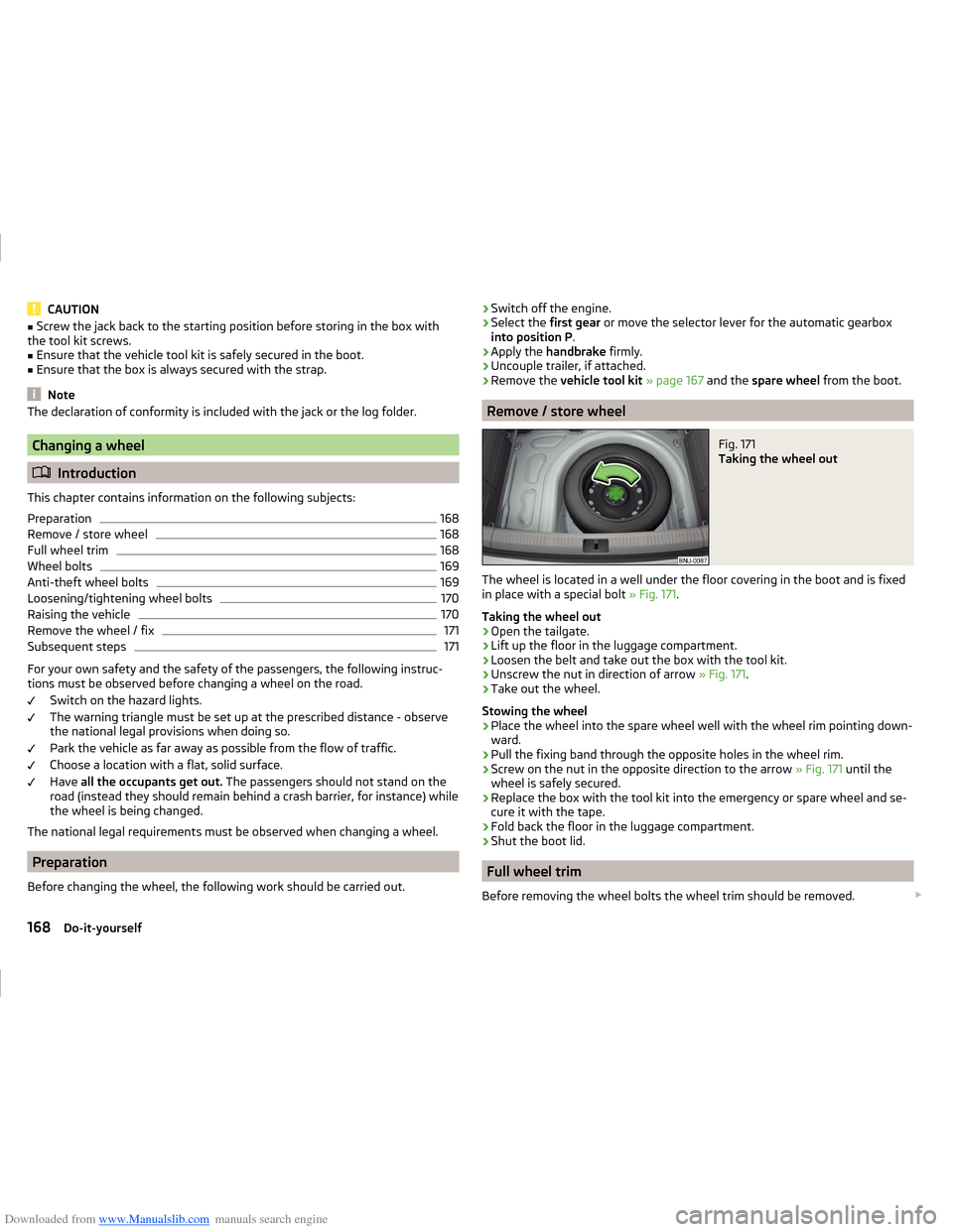
Fig. 171
Taking the wheel out
The wheel is located in a well under the floor covering in the boot and is fixed
in place with a special bolt » Fig. 171.
Taking the wheel out
›
Open the tailgate.
›
Lift up the floor in the luggage compartment.
›
Loosen the belt and take out the box with the tool kit.
›
Unscrew the nut in direction of arrow » Fig. 171.
›
Take out the wheel.
Stowing the wheel
›
Place the wheel into the spare wheel well with the wheel rim pointing down-
ward.
›
Pull the fixing band through the opposite holes in the wheel rim.
›
Screw on the nut in the opposite direction to the arrow » Fig. 171 until the
wheel is safely secured.
›
Replace the box with the tool kit into the emergency or spare wheel and se-
cure it with the tape.
›
Fold back the floor in the luggage compartment.
›
Shut the boot lid.
Full wheel trim
Before removing the wheel bolts the wheel trim should be removed.
168Do-it-yourself
Page 176 of 216
Downloaded from www.Manualslib.com manuals search engine General informationRead and observe
on page 172 first.
For your own safety and the safety of your passengers, the following instruc-
tions must be observed before carrying out a wheel repair on the road.
Switch on the hazard lights.
The warning triangle must be set up at the prescribed distance - observe
the national legal provisions when doing so.
Park the vehicle as far away as possible from the flow of traffic.
Choose a location with a flat, solid surface.
Have all the occupants get out. The passengers should not stand on the
road (instead they should remain behind a crash barrier, for instance) while
the wheel is being changed.
The national legal requirements must be observed when repairing a tyre.
The breakdown kit must not be used under the following circumstances. › The rim is damaged.
› The outside temperature is below -20 ° C.
› The cut or puncture is larger than 4 mm.
› The tyre wall is damaged.
› After the expiration date (see inflation bottle).
Preparations for using the breakdown kit
Read and observe
on page 172 first.
The following preparatory work must be carried out before using the break-
down kit.
›
Switch off the engine.
›
Select the first gear or move the selector lever for the automatic gearbox
into position P .
›
Apply the handbrake firmly.
›
Check that you can carry out the repairs with the breakdown kit » page 173,
General information .
›
Uncouple trailer, if attached.
›
Remove the breakdown kit from the boot.
›
Stick the corresponding sticker
1
» Fig. 177 on page 172 on the dashboard in
the driver's field of view.
›
Unscrew the valve cap.
› Use the valve remover 2 to unscrew the valve core and place it on a clean
surface (rag, paper, etc.).
Sealing and inflating the tyre
Read and observe
on page 172 first.
Sealing
›
Shake the tyre inflator bottle
10
» Fig. 177 on page 172 vigorously several
times.
›
Firmly screw the inflation hose
3
onto the tyre inflator bottle
10
in a clock-
wise direction. The film on the cap is pierced automatically.
›
Remove the plug from the inflation hose
3
and push the open end fully on-
to the tyre valve.
›
Hold the bottle
10
with the bottom facing upwards and fill all of the sealing
agent from the tyre inflator bottle into the tyre.
›
Remove the filler plug from the tyre valve.
›
Screw the valve core back into the tyre valve using the valve remover
2
.
Inflating
›
Screw the air compressor tyre inflation hose
7
» Fig. 177 on page 172 firmly
onto the tyre valve.
›
For vehicles with Manual transmission move the lever into the neutral posi-
tion and apply the parking brake firmly.
›
For vehicles with Automatic transmission move the selector lever to position
P and apply the parking brake firmly.
›
Start the engine and run it in idle.
›
Plug the connector
6
into 12 volt socket » page 78.
›
Switch on the air compressor with the ON and OFF switch
9
.
›
Allow the air compressor to run until a pressure of 2.0 - 2.5 bar is achieved.
Maximum run time of 8 minutes » .
›
Switch off the air compressor.
›
If you cannot reach an air pressure of 2.0 – 2.5 bar, unscrew the tyre inflation
hose
7
from the tyre valve.
›
Drive the vehicle 10 metres forwards or backwards to allow the sealing agent
to “distribute” in the tyre.
›
Firmly screw the tyre inflation hose
7
back onto the tyre valve and repeat
the inflation process.
›
If you still cannot reach the required tyre inflation pressure, this means the
tyre has sustained too much damage. You cannot seal with tyre with the
breakdown kit »
.
›
Switch off the air compressor.
173Emergency equipment, and self-help