window SKODA FABIA 2015 3.G / NJ User Guide
[x] Cancel search | Manufacturer: SKODA, Model Year: 2015, Model line: FABIA, Model: SKODA FABIA 2015 3.G / NJPages: 220, PDF Size: 32.46 MB
Page 60 of 220
WARNINGPower windows in the driver's door and the rear doors are equipped with a
force limiter (only applies to the Variant 2 ) » page 58 . If there is an obsta-
cle, the closing process is stopped and the window goes down by several
centimetres. The windows should nevertheless be closed carefully – risk of
injury.■
If the rear seats are accommodating people who are not completely inde-
pendent, e.g. children, it is recommended that for safety reasons the but-
tons in the rear doors are disabled with the button
E
» Fig. 45 .
CAUTION
■
Keep the windows clean to ensure the correct functionality of the electric
windows.■
In the winter, ice on the window may cause greater resistance as the win-
dow is closed. The window will stop and open again by several centimetres.
■
It is necessary to deactivate the force limiter to close the window
» page 58 .
■
Always close the sliding/tilting roof before disconnecting the battery.
Note
The window lift mechanism is equipped with protection against overheater.
Repeated opening and closing of the window can cause this mechanism to
overheat. If this happens, it will not be possible to operate the window for a
short time. You will be able to operate the window again as soon as the over-
heater protection has cooled down.
Opening the windows in the front passenger door and in the rear
doors
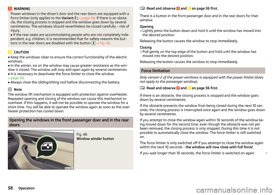
Fig. 46
Window winder button
Read and observe and on page 56 first.
There is a button in the front passenger door and in the rear doors for that
window.
Opening
›
Lightly press the button down and hold it until the window has moved into
the desired position.
Releasing the button causes the window to stop immediately.
Closing
›
Pull gently on the top edge of the button and hold until the window has
moved into the desired position.
Releasing the button causes the window to stop immediately.
Force limitation
Only version 2 of the power windows is equipped with the power limiter (does
not apply to the passenger window).
Read and observe
and on page 56 first.
If there is an obstacle, the closing process is stopped and the window goes
down by several centimetres.
If the obstacle prevents the window from being closed during the next 10 sec-
onds, the closing process is interrupted once again and the window goes down
by several centimetres.
If you attempt to close the window again within 10 seconds of the window be-
ing moved down for the second time, even though the obstacle was not yet
been removed, the closing process is only stopped. During this time it is not
possible to automatically close the window. The force limiter is still switched
on.
The force limiter is only switched off if you attempt to close the window again
within the next 10 seconds - the window will now close with full force!
If you wait longer than 10 seconds, the force limiter is switched on again.
58Operation
Page 61 of 220
WARNING■Variant 1 of the power window » Fig. 45 on page 57 has no force limiter.
The windows should be closed carefully – risk of injury!■
The passenger window in variant 2 of the power window » Fig. 45 on
page 57 has no force limiter. The window should nevertheless be closed
carefully – risk of injury!
Malfunctions
Read and observe
and on page 56 first.
If the battery has been disconnected and reconnected, it is possible that theautomatic window lifter will not operate. The system must be activated.
Activation sequence:
›
Switch on the ignition.
›
Pull the top edge of the button and close the window.
›
Release the button.
›
Pull the relevant button upwards again for approx. 1 seconds, and keep it
pressed down.
Lights and visibility
Lights
Introduction
This chapter contains information on the following subjects:
Operating the lights
60
Daylight running lights (DAY LIGHT)
60
Turn signal and main beam
61
Automatic driving lamp control
61
Front and rear fog light
62
Fog lights with the CORNER function
62
COMING HOME / LEAVING HOME
63
Hazard warning light system
63
Parking lights
63
Driving abroad
64
The lights work only with the ignition on, unless otherwise stated.
The layout of the controls on right-hand drive vehicles differs partially from
that shown in » Fig. 47 on page 60 . The symbols which mark the positions of
the controls are identical.
Keep the headlights lenses clean » page 143, Headlight glasses .
WARNINGThe automatic driving lamp control only operates as a support and
does not release the driver from his responsibility to check the lights and, if
necessary, to switch on the light depending on the prevailing light condi-
tions. 59Lights and visibility
Page 67 of 220
Visibility
Introduction
This chapter contains information on the following subjects:
Rear window heater
65
Sun visors in the front
65
Sun screen of the panoramic roof
66WARNINGMake sure that the view outside is not covered by ice, snow, mist or other
objects.
Rear window heater
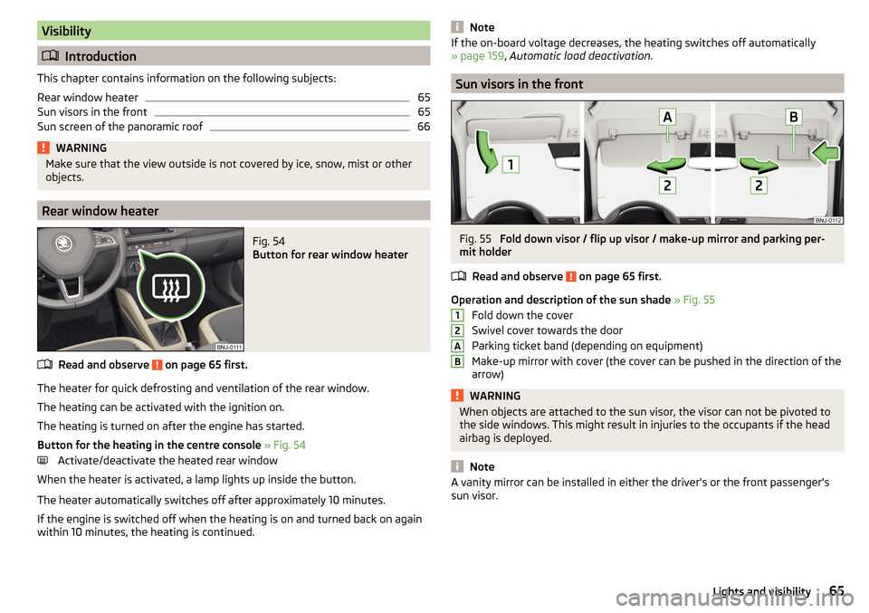
Fig. 54
Button for rear window heater
Read and observe on page 65 first.
The heater for quick defrosting and ventilation of the rear window.
The heating can be activated with the ignition on.
The heating is turned on after the engine has started.
Button for the heating in the centre console » Fig. 54
Activate/deactivate the heated rear window
When the heater is activated, a lamp lights up inside the button.
The heater automatically switches off after approximately 10 minutes.
If the engine is switched off when the heating is on and turned back on again
within 10 minutes, the heating is continued.
NoteIf the on-board voltage decreases, the heating switches off automatically
» page 159 , Automatic load deactivation .
Sun visors in the front
Fig. 55
Fold down visor / flip up visor / make-up mirror and parking per-
mit holder
Read and observe
on page 65 first.
Operation and description of the sun shade » Fig. 55
Fold down the cover
Swivel cover towards the door
Parking ticket band (depending on equipment)
Make-up mirror with cover (the cover can be pushed in the direction of the
arrow)
WARNINGWhen objects are attached to the sun visor, the visor can not be pivoted to
the side windows. This might result in injuries to the occupants if the head
airbag is deployed.
Note
A vanity mirror can be installed in either the driver's or the front passenger's
sun visor.12AB65Lights and visibility
Page 68 of 220
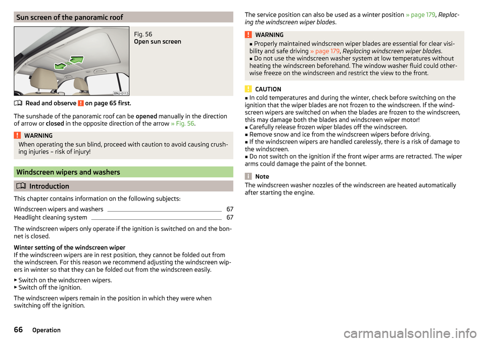
Sun screen of the panoramic roofFig. 56
Open sun screen
Read and observe on page 65 first.
The sunshade of the panoramic roof can be opened manually in the direction
of arrow or closed in the opposite direction of the arrow » Fig. 56.
WARNINGWhen operating the sun blind, proceed with caution to avoid causing crush-
ing injuries – risk of injury!
Windscreen wipers and washers
Introduction
This chapter contains information on the following subjects:
Windscreen wipers and washers
67
Headlight cleaning system
67
The windscreen wipers only operate if the ignition is switched on and the bon-
net is closed.
Winter setting of the windscreen wiper
If the windscreen wipers are in rest position, they cannot be folded out from
the windscreen. For this reason we recommend adjusting the windscreen wip-
ers in winter so that they can be folded out from the windscreen easily.
▶ Switch on the windscreen wipers.
▶ Switch off the ignition.
The windscreen wipers remain in the position in which they were when
switching off the ignition.
The service position can also be used as a winter position » page 179, Replac-
ing the windscreen wiper blades .WARNING■
Properly maintained windscreen wiper blades are essential for clear visi-
bility and safe driving » page 179, Replacing windscreen wiper blades .■
Do not use the windscreen washer system at low temperatures without
heating the windscreen beforehand. The window washer fluid could other-
wise freeze on the windscreen and restrict the view to the front.
CAUTION
■ In cold temperatures and during the winter, check before switching on the
ignition that the wiper blades are not frozen to the windscreen. If the wind-
screen wipers are switched on when the blades are frozen to the windscreen,
this may damage both the blades and windscreen wiper motor!■
Carefully release frozen wiper blades off the windscreen.
■
Remove snow and ice from the windscreen wipers before driving.
■
If the windscreen wipers are handled carelessly, there is a risk of damage to
the windscreen.
■
Do not switch on the ignition if the front wiper arms are retracted. The wiper
arms could damage the paint of the bonnet.
Note
The windscreen washer nozzles of the windscreen are heated automatically
after starting the engine.66Operation
Page 69 of 220
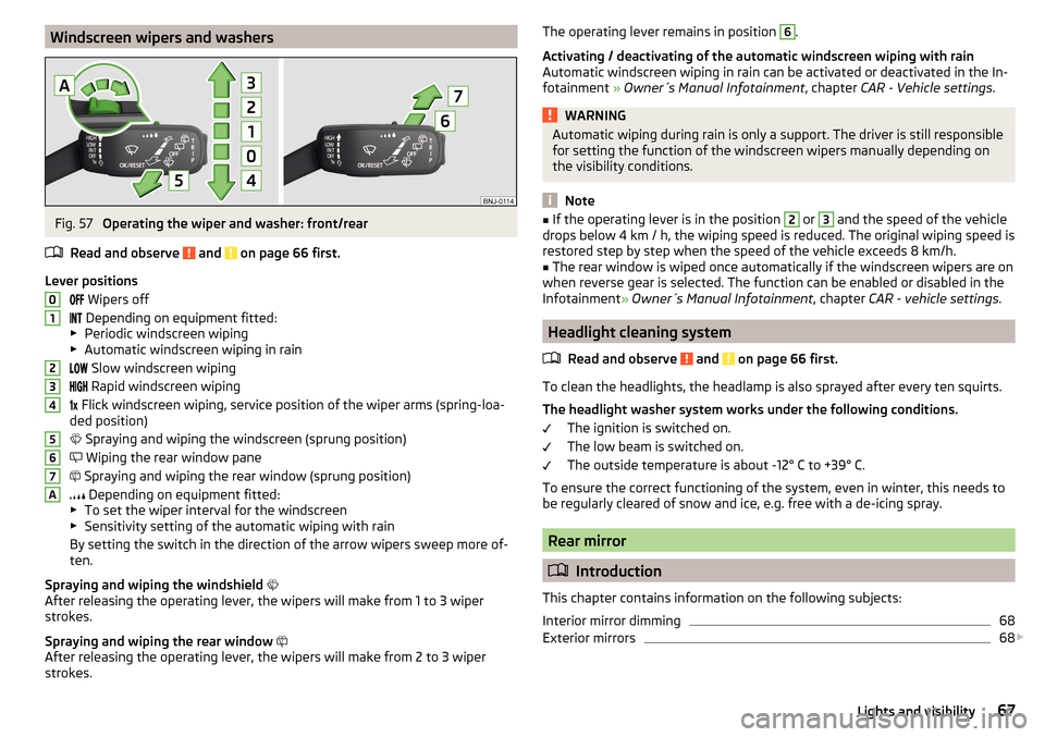
Windscreen wipers and washersFig. 57
Operating the wiper and washer: front/rear
Read and observe
and on page 66 first.
Lever positions Wipers off
Depending on equipment fitted:
▶ Periodic windscreen wiping
▶ Automatic windscreen wiping in rain
Slow windscreen wiping
Rapid windscreen wiping
Flick windscreen wiping, service position of the wiper arms (spring-loa-
ded position)
Spraying and wiping the windscreen (sprung position)
Wiping the rear window pane
Spraying and wiping the rear window (sprung position)
Depending on equipment fitted:
▶ To set the wiper interval for the windscreen
▶ Sensitivity setting of the automatic wiping with rain
By setting the switch in the direction of the arrow wipers sweep more of-
ten.
Spraying and wiping the windshield
After releasing the operating lever, the wipers will make from 1 to 3 wiper
strokes.
Spraying and wiping the rear window
After releasing the operating lever, the wipers will make from 2 to 3 wiper
strokes.
01234567AThe operating lever remains in position 6.
Activating / deactivating of the automatic windscreen wiping with rain
Automatic windscreen wiping in rain can be activated or deactivated in the In-
fotainment » Owner´s Manual Infotainment , chapter CAR - Vehicle settings .WARNINGAutomatic wiping during rain is only a support. The driver is still responsible
for setting the function of the windscreen wipers manually depending on
the visibility conditions.
Note
■ If the operating lever is in the position 2 or 3 and the speed of the vehicle
drops below 4 km / h, the wiping speed is reduced. The original wiping speed is
restored step by step when the speed of the vehicle exceeds 8 km/h.■
The rear window is wiped once automatically if the windscreen wipers are on
when reverse gear is selected. The function can be enabled or disabled in the
Infotainment » Owner´s Manual Infotainment , chapter CAR - vehicle settings .
Headlight cleaning system
Read and observe
and on page 66 first.
To clean the headlights, the headlamp is also sprayed after every ten squirts.The headlight washer system works under the following conditions. The ignition is switched on.
The low beam is switched on.
The outside temperature is about -12° C to +39° C.
To ensure the correct functioning of the system, even in winter, this needs to be regularly cleared of snow and ice, e.g. free with a de-icing spray.
Rear mirror
Introduction
This chapter contains information on the following subjects:
Interior mirror dimming
68
Exterior mirrors
68
67Lights and visibility
Page 71 of 220
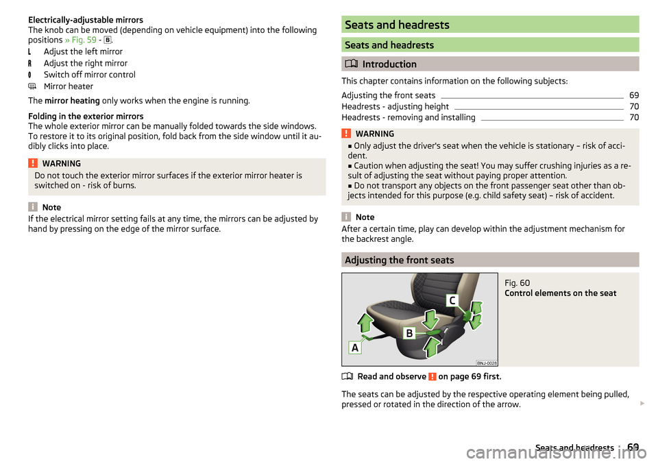
Electrically-adjustable mirrors
The knob can be moved (depending on vehicle equipment) into the following
positions » Fig. 59 -
.
Adjust the left mirror
Adjust the right mirror
Switch off mirror control
Mirror heater
The mirror heating only works when the engine is running.
Folding in the exterior mirrors
The whole exterior mirror can be manually folded towards the side windows.
To restore it to its original position, fold back from the side window until it au-
dibly clicks into place.WARNINGDo not touch the exterior mirror surfaces if the exterior mirror heater is
switched on - risk of burns.
Note
If the electrical mirror setting fails at any time, the mirrors can be adjusted by
hand by pressing on the edge of the mirror surface.Seats and headrests
Seats and headrests
Introduction
This chapter contains information on the following subjects:
Adjusting the front seats
69
Headrests - adjusting height
70
Headrests - removing and installing
70WARNING■ Only adjust the driver's seat when the vehicle is stationary – risk of acci-
dent.■
Caution when adjusting the seat! You may suffer crushing injuries as a re-
sult of adjusting the seat without paying proper attention.
■
Do not transport any objects on the front passenger seat other than ob-
jects intended for this purpose (e.g. child safety seat) – risk of accident.
Note
After a certain time, play can develop within the adjustment mechanism for
the backrest angle.
Adjusting the front seats
Fig. 60
Control elements on the seat
Read and observe on page 69 first.
The seats can be adjusted by the respective operating element being pulled,
pressed or rotated in the direction of the arrow.
69Seats and headrests
Page 86 of 220
When transporting cargo the instructions below must be followed
▶ When transporting heavy objects, the driving characteristics change due to
the shift in the centre of gravity. The speed and style of driving must be ad-
justed accordingly.
▶ The cargo is stowed in the luggage compartment. To prevent this from mov-
ing, it should be secured with suitable lashing straps to the lashing eyes or
secured with fixing nets.
▶ Distribute loads as evenly as possible.
▶ Place heavy objects as far forward as possible.
▶ Items carried in the luggage compartment must be stowed in such a way
that no objects are able to slip forward under sudden driving manoeuvres or
braking – risk of injury.
▶ Match the tyre pressure to the load.
▶ When transporting loads in the luggage compartment that has been en-
larged by folding the rear seats forward, ensure the safety of the passengers
transported on the other rear seats.
In the event of an accident, even small and light objects gain so much kinetic energy that they can cause severe injuries.
The magnitude of the kinetic energy is dependent on the speed at which the
vehicle is travelling and the weight of the object.
Example: In the event of a frontal collision at a speed of 50 km/h, an object
weighing 4.5 kg produces energy corresponding to 20 times its own weight.
This means that it results in a weight of approx. 90 kg “ ”.
Luggage compartment light
The warning light turns on when tailgate is opened.
The warning light turns off when the tailgate is closed.
If the boot lid is open and the ignition switched off, the light will extinguish
automatically after around 10 minutes.WARNING■ Never exceed the maximum permissible load of the respective fasteners,
nets, hooks etc., as heavy objects are not sufficiently secured - there is a
risk of injury!■
If the cargo is tied down with unsuitable or damaged lashing straps, inju-
ries can occur in the event of braking manoeuvres or accidents.
WARNING (Continued)■ Loose cargo can be thrown forward during a sudden manoeuvre or in case
of an accident, and can injure the occupants or other road users.■
Loose cargo could hit a deployed airbag and injure occupants – danger of
death!
CAUTION
■ Never exceed the maximum permissible load of the respective fasteners,
nets, hooks etc. - these could be damaged.■
Please ensure that the heating elements for the rear window heater are not
damaged as a result of abrasive objects.
Fastening elements
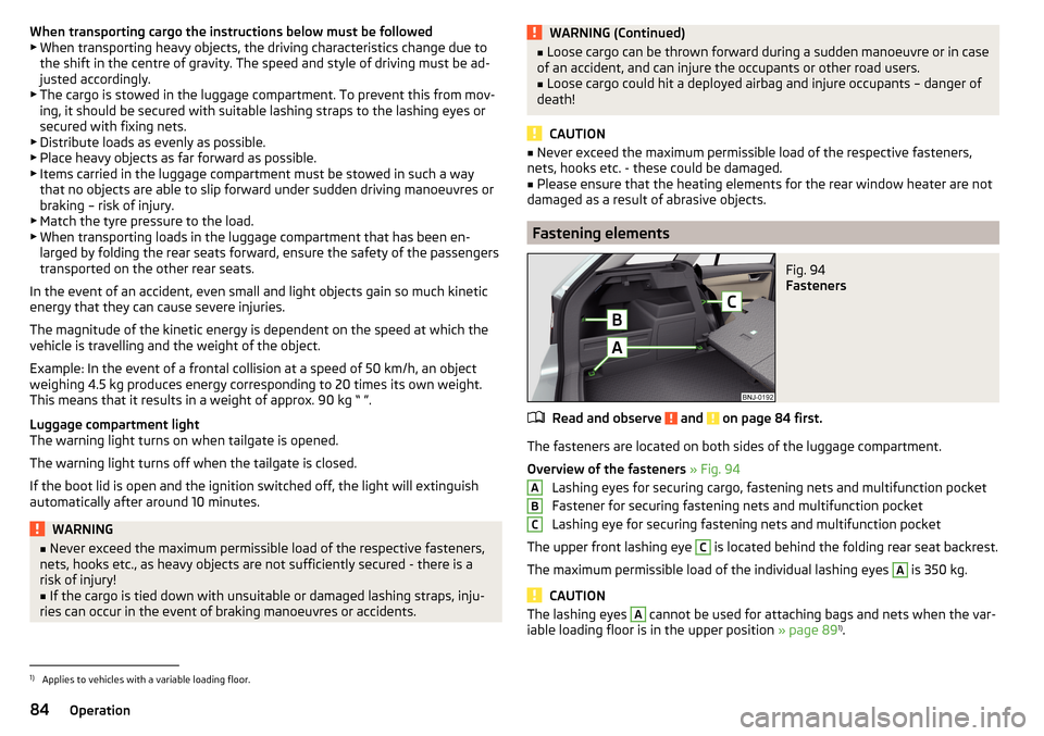
Fig. 94
Fasteners
Read and observe and on page 84 first.
The fasteners are located on both sides of the luggage compartment.
Overview of the fasteners » Fig. 94
Lashing eyes for securing cargo, fastening nets and multifunction pocket
Fastener for securing fastening nets and multifunction pocket
Lashing eye for securing fastening nets and multifunction pocket
The upper front lashing eye
C
is located behind the folding rear seat backrest.
The maximum permissible load of the individual lashing eyes
A
is 350 kg.
CAUTION
The lashing eyes A cannot be used for attaching bags and nets when the var-
iable loading floor is in the upper position » page 891)
.ABC1)
Applies to vehicles with a variable loading floor.
84Operation
Page 95 of 220
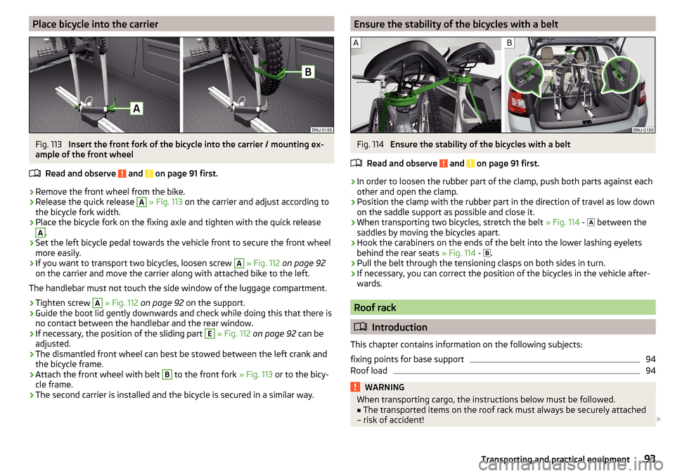
Place bicycle into the carrierFig. 113
Insert the front fork of the bicycle into the carrier / mounting ex-
ample of the front wheel
Read and observe
and on page 91 first.
›
Remove the front wheel from the bike.
›
Release the quick release
A
» Fig. 113 on the carrier and adjust according to
the bicycle fork width.
›
Place the bicycle fork on the fixing axle and tighten with the quick release
A
.
›
Set the left bicycle pedal towards the vehicle front to secure the front wheel
more easily.
›
If you want to transport two bicycles, loosen screw
A
» Fig. 112 on page 92
on the carrier and move the carrier along with attached bike to the left.
The handlebar must not touch the side window of the luggage compartment.
›
Tighten screw
A
» Fig. 112 on page 92 on the support.
›
Guide the boot lid gently downwards and check while doing this that there is
no contact between the handlebar and the rear window.
›
If necessary, the position of the sliding part
E
» Fig. 112 on page 92 can be
adjusted.
›
The dismantled front wheel can best be stowed between the left crank and
the bicycle frame.
›
Attach the front wheel with belt
B
to the front fork » Fig. 113 or to the bicy-
cle frame.
›
The second carrier is installed and the bicycle is secured in a similar way.
Ensure the stability of the bicycles with a beltFig. 114
Ensure the stability of the bicycles with a belt
Read and observe
and on page 91 first.
›
In order to loosen the rubber part of the clamp, push both parts against each
other and open the clamp.
›
Position the clamp with the rubber part in the direction of travel as low down
on the saddle support as possible and close it.
›
When transporting two bicycles, stretch the belt » Fig. 114 -
between the
saddles by moving the bicycles apart.
›
Hook the carabiners on the ends of the belt into the lower lashing eyelets
behind the rear seats » Fig. 114 -
.
›
Pull the belt through the tensioning clasps on both sides in turn.
›
If necessary, you can correct the position of the bicycles in the vehicle after-
wards.
Roof rack
Introduction
This chapter contains information on the following subjects:
fixing points for base support
94
Roof load
94WARNINGWhen transporting cargo, the instructions below must be followed.■The transported items on the roof rack must always be securely attached
– risk of accident! 93Transporting and practical equipment
Page 97 of 220
Heating and ventilation
Heating, manual air conditioning system, Climatronic
Introduction
This chapter contains information on the following subjects:
Heating and manual air conditioning
95
Climatronic (automatic air conditioning)
96
Climatronic - automatic operation
97
Recirculated air mode
97
Air outlet vents
98
The heating and air conditioning systems ventilate and heat the vehicle interi-
or. The air conditioning system also cools and dehumidifies the vehicle interior.
The heating effect is dependent upon the coolant temperature, thus full heat
output only occurs when the engine has reached its operating temperature.
The heating and air conditioning systems only operate when the ignition is
switched on.
The cooling system operates only if the following conditions are met. The cooling system is switched on.
The engine is running.
The outside temperature is above approximately +2 °C.
The blower is switched on.
If the cooling system is switched on, the temperature and air humidity drops in the vehicle. The cooling system prevents the windows from misting up during
winter months.
It is possible to briefly activate re-circulated air mode to enhance the cooling
effect » page 97 .
Health protection
To reduce health risks (e.g. common colds), the following instructions for the
use of the cooling system are to be observed. ▶ The difference between the indoor temperature and the outdoor air temper-
ature should not be greater than about 5 ° C.
▶ The cooling system is to be turned off about 10 minutes before the end of
the journey.
▶ Once a year, have the manual air conditioner or Climatronic system disinfec-
ted by a specialist company.WARNING■ For your own safety and that of other road users, ensure that all the win-
dows are free of ice, snow and misting. The blower should always be on to
prevent the windows from misting up.■
Under certain circumstances, air at a temperature of about 5 °C can flow
out of the vents when the cooling system is switched on.
CAUTION
■ The air inlet in front of the windscreen must be free (e.g. of ice, snow or
leaves) to ensure that the heating and cooling system operates properly.■
After switching on the cooling system condensation from the evaporator of
the air conditioning may drip down and form a puddle below the vehicle. This is
not a leak!
■
If the coolant temperature is too high, the cooling system is switched off to
ensure that the engine cools down.
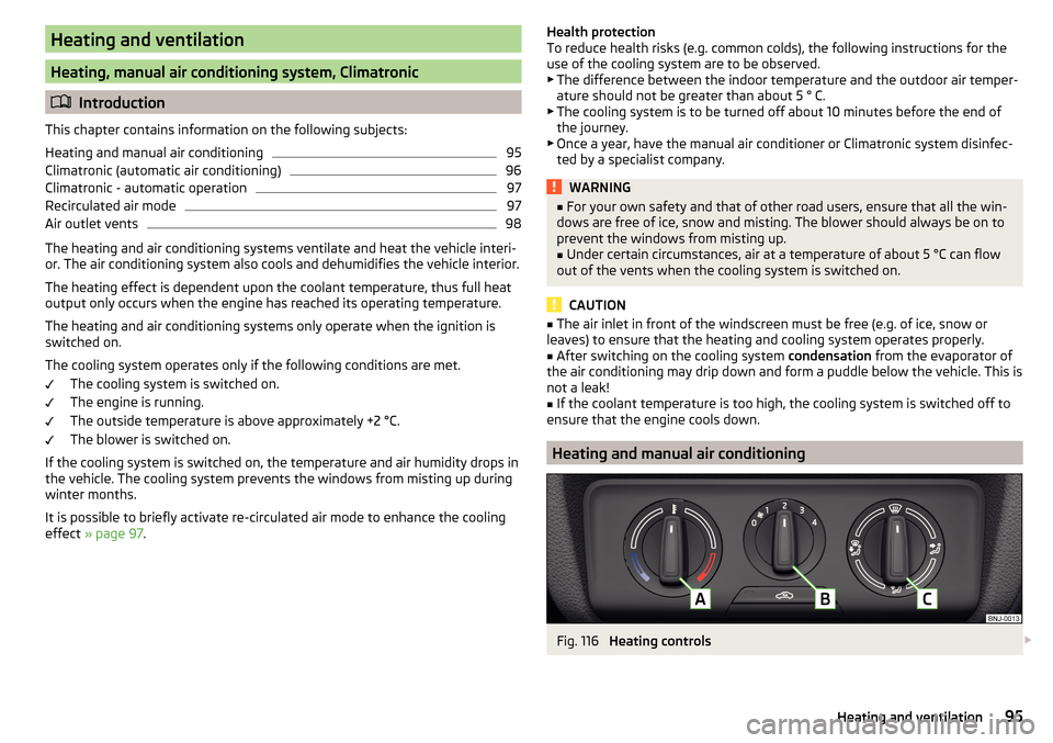
Heating and manual air conditioning
Fig. 116
Heating controls
95Heating and ventilation
Page 98 of 220
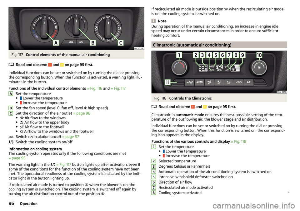
Fig. 117
Control elements of the manual air conditioning
Read and observe
and on page 95 first.
Individual functions can be set or switched on by turning the dial or pressing the corresponding button. When the function is activated, a warning light illu-
minates in the button.
Functions of the individual control elements » Fig. 116 and » Fig. 117
Set the temperature
▶ Lower the temperature
▶ Increase the temperature
Set the fan speed (level 0: fan off, level 4: high speed)
Set the direction of the air outlet » page 98
▶ Air flow to the windows
▶ Air flow to the upper body
▶ Air flow to the footwell
▶ Airflow to the windows and the footwell
Switch recirculation on/off » page 97
Switch the cooling system on/off
Information on cooling system
The cooling system operates only if the following conditions are met
» page 95 .
The warning light in the
» Fig. 117 button lights up after activation, even if
some of the conditions for the function of the cooling system have not been
met. The operational readiness of the cooling system is indicated by the indi-
cator light in the button lighting up.
If recirculated air mode is turned to position when the blower is on, the
cooling system is switched on. The cooling system is switched off again by
turning the air distribution control out of the position .
ABCIf recirculated air mode is outside position
when the recirculating air mode
is on, the cooling system is switched on.
Note
During operation of the manual air conditioning, an increase in engine idle
speed may occur under certain circumstances in order to ensure sufficient
heating comfort.
Climatronic (automatic air conditioning)
Fig. 118
Controls the Climatronic
Read and observe
and on page 95 first.
Climatronic in automatic mode ensures the best-possible setting of the tem-
perature of the outflowing air, the blower stage and air distribution.
Individual functions can be set or switched on by turning the dial or pressing the corresponding button. When this function is switched on, the correspond-
ing icon appears in the display.
Functions of the various controls and display » Fig. 118
Set the temperature
▶ Lower the temperature
▶ Increase the temperature
Selected temperature
Degrees Celsius or Fahrenheit
Automatic operation of the air conditioning system is switched on
Intensive windshield defroster switched on
Direction of air flow
Recirculated air mode activated
Cooling system activated
1234567896Operation