sensor SKODA FABIA 2016 3.G / NJ User Guide
[x] Cancel search | Manufacturer: SKODA, Model Year: 2016, Model line: FABIA, Model: SKODA FABIA 2016 3.G / NJPages: 196, PDF Size: 31.86 MB
Page 106 of 196
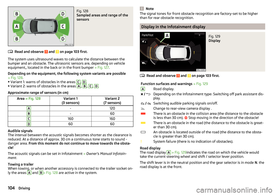
Fig. 128
Sampled areas and range of the
sensors
Read and observe and on page 103 first.
The system uses ultrasound waves to calculate the distance between the
bumper and an obstacle. The ultrasonic sensors are, depending on vehicle
equipment,, located in the back or in the front bumper » Fig. 127.
Depending on the equipment, the following system variants are possible
» Fig. 128 .
▶ Variant 1: warns of obstacles in the areas
C
,
D
.
▶ Variant 2: warns of obstacles in the areas
A
,
B
,
C
,
D
.
Approximate range of sensors (in cm)
Area » Fig. 128Variant 1
(3 sensors)Variant 2
(7 sensors)A-120B-60C160160D6060
Audible signals
The interval between the acoustic signals becomes shorter as the clearance is
reduced. At a distance of approx. 30 cm a continuous tone starts to sound -
danger area. From this moment do not continue to move towards the obsta-
cle!
The acoustic signals can be set in Infotainment » Owner's Manual Infotain-
ment .
Towing a trailer
When towing, or when another accessory is connected to the trailer socket on-
ly the areas
A
and
B
» Fig. 128 are active in the system.
NoteThe signal tones for front obstacle recognition are factory-set to be higher
than for rear obstacle recognition.
Display in the Infotainment display
Fig. 129
Display
Read and observe and on page 103 first.
Function surfaces and warnings » Fig. 129ARoad display. Depending on the Infotainment type: Switching off park assistant dis-
play. Switching audible parking signals on/off.Change to rear-view camera display .There is an obstacle in the collision area (the distance to the obstacle
is less than 30 cm).
Stop moving in the direction of the obstacle!There is an obstacle in the road (the distance to the obstacle is great-
er than 30 cm).An obstacle is located outside of the road (the distance to the obsta-
cle is greater than 30 cm).System failure (there is no indication of obstacles).
Road display
The road display
A
» Fig. 129 indicates the road on which the vehicle would
take the current steering wheel and shift / selector lever position.
The shift lever is in the neutral position and the gear selector is in mode N. the
road display is at the front.
104Driving
Page 108 of 196

WARNING■The general information relating to the use of assistance systems must
be observed » page 100, in section Introduction .■
The camera may not be soiled or obscured, otherwise the system function
will be significantly affected - there is a risk of accident. For information on
cleaning » page 132 , Exterior car care .
CAUTION
■
The camera image is distorted by contrast with eyesight. The display is
therefore only of limited use for estimating distances to following vehicles.■
Some items, such as thin columns, chain link fences or lattice, may not be
represented adequately in terms of display resolution.
■
In a crash or damage the vehicle's rear camera can possibly deviate from the
correct position. If this is the case, have the sensor checked by a specialist ga-
rage.
Note
The camera can be equipped with a cleaning system » page 60. The spraying is
carried out automatically when the rear window is sprayed.
Operation
Fig. 132
Installation location of the camera / scanned area behind the ve-
hicle
Read and observe
and on page 106 first.
The camera for capturing the area behind the vehicle is in the grip of the bootlid » Fig. 132 .
Area behind the vehicle » Fig. 132
Detection range of the camera
Area outside the detection range of the camera
The system can assist the driver when parking and manoeuvring under the fol-
lowing basic conditions.
The ignition is switched on.
The reverse gear is engaged. 1)
The luggage compartment lid is completely closed.
The vehicle is travelling at less than 15 km/h.
The area behind the vehicle is clearly visible.
The selected parking / manoeuvring area is clear and even.
Note
■ The display can be interrupted by pressing the symbol button » Fig. 130 on
page 105 .■
After disengaging the reverse gear, automatic display of the parking aid is
carried out (variant 2, 3) » page 103.
Guidelines and function interfaces
Fig. 133
Infotainment Display: Orientation lines / functional surfaces
Read and observe
and on page 106 first.
Orientation lines are shown along with the monitored area behind the vehicle
in the display.
AB1)
The area behind the vehicle can be displayed for a few seconds more after disengaging the reverse gear.
106Driving
Page 112 of 196
NoteBy pressing the button D during the control this is cancelled and the CCS is
activated.
Adaptive Cruise Control (ACC)
Introduction
This chapter contains information on the following subjects:
Operation
110
Automatic stop-start
111
Operation overview
111
Start control
112
Stop/resume control
112
Set/change the desired speed
112
Set the clearance level
113
Special driving conditions
113
Overtaking and towing
114
Malfunctions
114
The Adaptive Cruise Control (hereinafter referred to as ACC) maintains the set
speed or the distance to the vehicle ahead without the accelerator or brake
pedal being pressed.
The front of the vehicle and the distance to the vehicle ahead is monitored by
a radar sensor » page 100.
The state in which the ACC maintains the speed or the proximity is described
as control from here on.
WARNING■
The general information relating to the use of assistance systems must
be observed » page 100, in section Introduction .■
The driver must always be ready to take over the operation of the accel-
erator and brake pedal.
■
The ACC does not react when approaching a stationary obstacle, such as
traffic jams, vehicle breakdowns or vehicles waiting at a traffic light.
■
The ACC does not respond to crossing or oncoming objects.
■
If the ACC does not decelerate fast enough, immediately apply the vehi-
cle's foot brake.
WARNINGFor safety reasons, do not use the ACC under the following conditions.■When driving in turning lanes, motorway exits or construction sites, to
avoid an unwanted acceleration to the stored speed.■
When visibility is poor, (e.g. fog, heavy rain, thick snowfall).
■
When road conditions are poor (e.g. ice, slippery road, gravel, dirt road).
■
Driving into “sharp” corners or in steep gradients / on steep inclines.
■
When driving through places where metal objects (such as metal build-
ings, railway tracks, etc.) can be found.
■
When driving through very divided and enclosed spaces (such as large-ca-
pacity garages, car ferries, tunnels and the like.).
Note
■ The ACC is designed primarily for use on motorways.■The ACC reduces the speed by automatically releasing the accelerator or by
means of a braking procedure as appropriate. If the brakes are used for an au-
tomatic speed reduction at any moments, then the brake light illuminates.■
In case of failure of more than one brake light on the vehicle or on the con-
nected trailer, the ACC becomes unavailable.
■
The control automatically cancels the engagement of the brake supportive
assistance systems (e.g. ESC) or when the maximum permitted engine speed is
exceeded.
Operation
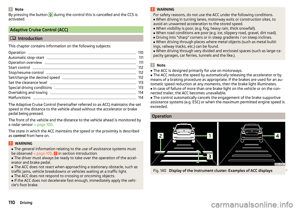
Fig. 140
Display of the instrument cluster: Examples of ACC displays
110Driving
Page 113 of 196

Fig. 141
Display of the instrument cluster: Examples of ACC status dis-
plays
Read and observe
on page 110 first.
The ACC allows a speed of 30-160 km/h to be set or a distance to the preced-
ing vehicle to be very short of very long to be set.
The ACC adjusts the set speed with respect to the detected vehicle ahead,
thus maintaining the selected proximity.
The ACC can detect a vehicle that is up to approx. 120 m ahead using the radar
sensor.
ACC display » Fig. 140
Vehicle detected (control active)
Line showing the displacement of the distance when setting » page 113,
Set the clearance level
Set distance to the vehicle ahead
Vehicle detected (control deactivated)
ACC status displays » Fig. 141
Control deactivated.
Control activated - no vehicle detected.
Regulation deactivated - no speed stored.
Control activated (vehicle detected).
Note to reduce speed
If the delay of the ACC is insufficient in relation to the vehicle in front, the
warning light lights up in the instrument cluster and the display shows a
message to engage the brake pedal.
1234NoteSome ACC notifications in the display of the instrument cluster may be hidden
by notifications for other functions. An ACC notification automatically appears
for a brief moment when there is a change in status of the ACC.
Automatic stop-start
Read and observe
on page 110 first.
Vehicles with an automatic transmission can decelerate to a complete stop
and start moving again using the ACC.
Decelerate to a complete stop
If a vehicle ahead decelerates to a standstill, the ACC will also decelerate your
vehicle to a complete stop.
Starting to drive again after a holding period
As soon as the vehicle ahead starts moving again after a holding period, your
vehicle will also move and the speed will continue to be controlled. Control is
automatically disconnected in case of longer holding periods.
Operation overview
Fig. 142
Operating lever
Read and observe
on page 110 first.
Overview of ACC functions operated with the lever » Fig. 1421Activate ACC (control deactivated)2Start control (resume) / increase speed by 1 km/h at a time
(sprung position)3Interrupt control (sprung position) 111Assist systems
Page 116 of 196

Overtaking and towingRead and observe
on page 110 first.
When overtaking
When your vehicle is being controlled at a speed that is lower than the set
speed and the turn signal is operated, ACC assesses this situation as meaning
that the driver wishes to overtake. The ACC automatically accelerates the vehi-
cle, thereby reducing the proximity to a vehicle ahead.
If your vehicle changes to the overtaking lane and no vehicle is detected
ahead, ACC accelerates until the set speed is reached and then keeps it con-
stant.
Acceleration can be cancelled at any time by touch on the brake pedal or
pressing the button on the lever
» Fig. 142 on page 111 .
Towing a trailer
When towing, or if another accessory is connected to the trailer socket, ACC control is set with a lower rate. The manner of driving should therefore be
adapted to this limitation.
Malfunctions
Read and observe
on page 110 first.
If, for some unknown reason, ACC is not available, the warning light appears
in the display of the instrument cluster and an appropriate message is shown.
Sensor covered / dirty
If the sensor is dirty or covered, a message indicating that there is no sensor
view appears. Clean the sensor cover or remove the obstacles » Fig. 125 on
page 100 .
ACC not available
If the ACC is currently unavailable, a message concerning the unavailability ap-
pears. Stop the vehicle, switch off the engine and then start it again. If ACC
continues to be unavailable, seek the assistance of a specialist garage.
ACC fault
With an ACC fault, an error message appears. Seek help from a specialist ga-
rage.
Front Assist
Introduction
This chapter contains information on the following subjects:
Operation
114
Distance warning
115
Warning and automatic braking
115
Deactivation/activation
116
Malfunctions
116
The Front Assist (hereinafter referred to as "system") warns you of the danger
of a collision with a vehicle or another obstacle in front of the vehicle, and tries
to avoid a collision or mitigate its consequences by automatically applying the
brakes where necessary.
The area in front of the vehicle is monitored by a radar sensor » page 100.
WARNING■
The general information relating to the use of assistance systems must
be observed » page 100, in section Introduction .■
The system does not respond to crossing or oncoming objects.
CAUTION
In case of failure of more than one brake light on the vehicle or on the electri-
cally connected trailer, the system becomes unavailable.
Operation
Read and observe
and on page 114 first.
The system support is provided in the following manner.▶ Alerts you about a dangerous proximity to the vehicle ahead.
▶ Warns you of an impending collision.
▶ Assists with a brake action triggered by the driver.
▶ If the driver fails to respond to a detected danger, an automatic braking ac-
tion is performed.
The system can work only if the following basic conditions are met. The system is activated.
TCS is activated » page 102.
The vehicle is travelling forwards at a speed of more than approx. 5 km/h.
114Driving
Page 118 of 196
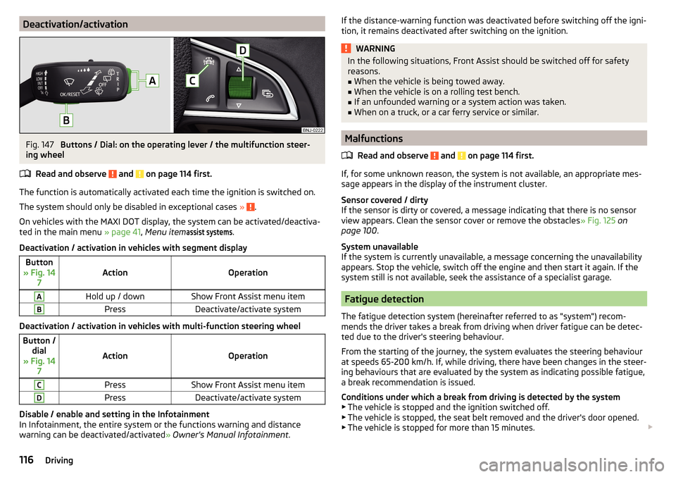
Deactivation/activationFig. 147
Buttons / Dial: on the operating lever / the multifunction steer-
ing wheel
Read and observe
and on page 114 first.
The function is automatically activated each time the ignition is switched on.
The system should only be disabled in exceptional cases »
.
On vehicles with the MAXI DOT display, the system can be activated/deactiva- ted in the main menu » page 41, Menu item
assist systems
.
Deactivation / activation in vehicles with segment display
Button
» Fig. 14 7ActionOperation
AHold up / downShow Front Assist menu itemBPressDeactivate/activate system
Deactivation / activation in vehicles with multi-function steering wheel
Button /dial
» Fig. 14 7
ActionOperation
CPressShow Front Assist menu itemDPressDeactivate/activate system
Disable / enable and setting in the Infotainment
In Infotainment, the entire system or the functions warning and distance
warning can be deactivated/activated » Owner's Manual Infotainment .
If the distance-warning function was deactivated before switching off the igni-
tion, it remains deactivated after switching on the ignition.WARNINGIn the following situations, Front Assist should be switched off for safety
reasons.■
When the vehicle is being towed away.
■
When the vehicle is on a rolling test bench.
■
If an unfounded warning or a system action was taken.
■
When on a truck, or a car ferry service or similar.
Malfunctions
Read and observe
and on page 114 first.
If, for some unknown reason, the system is not available, an appropriate mes-
sage appears in the display of the instrument cluster.
Sensor covered / dirty
If the sensor is dirty or covered, a message indicating that there is no sensor
view appears. Clean the sensor cover or remove the obstacles » Fig. 125 on
page 100 .
System unavailable
If the system is currently unavailable, a message concerning the unavailability
appears. Stop the vehicle, switch off the engine and then start it again. If the
system still is not available, seek the assistance of a specialist garage.
Fatigue detection
The fatigue detection system (hereinafter referred to as "system") recom-
mends the driver takes a break from driving when driver fatigue can be detec-
ted due to the driver's steering behaviour.
From the starting of the journey, the system evaluates the steering behaviour
at speeds 65-200 km/h. If, while driving, there have been changes in the steer-
ing behaviours that are evaluated by the system as indicating possible fatigue,
a break recommendation is issued.
Conditions under which a break from driving is detected by the system ▶ The vehicle is stopped and the ignition switched off.
▶ The vehicle is stopped, the seat belt removed and the driver's door opened.
▶ The vehicle is stopped for more than 15 minutes.
116Driving
Page 131 of 196
WARNING■No changes may be made to airbag system components, the front bump-
er and the bodywork.■
Any work on the airbag system including the installation and removal of
system components due to other repair work (e.g. removal of the steering
wheel) must only be carried out by a specialist garage.
■
Do not manipulate individual parts of the airbag system, as this might re-
sult in the airbag being deployed.
■
If the airbag has been deployed, the airbag system must be replaced.
WARNINGThe airbag system operates using pressure sensors located in the front
doors. For this reason, no adjustments may be carried out to the doors or
door panels (e.g. installation of additional loudspeakers). Resulting damage
can impair the functioning of the airbag system - risk of accidents and fatal
injuries! The following guidelines must therefore be observed.■
Any work on the front doors and their door panels must be carried out by
a specialist garage.
■
Never drive the vehicle with the inner door panels removed or with open-
ings in the panelling.
Acceptance and recycling of used vehicles
Read and observe
on page 127 first.
All new ŠKODA vehicles are 95% recyclable.
Service intervals
Introduction
This chapter contains information on the following subjects:
Overview of service intervals
130
Fixed service intervals QI1 - QI4
130
Variable service interval QI6
130
Digital Service Plan
131
The service interval display in the display of the instrument cluster will remind
you to carry out every service stipulated by the manufacturer at the right time
in order to prevent you from forgetting any » page 41.
The completion of services can be verified through the printed verification
from the digital service schedule and the respective receipts.
The specified service intervals are tailored to normal operating conditions.
In the case of aggravated operating conditions, it will be necessary to have
some service work carried out before the date of the next regular service or
between the specified service intervals. This applies mainly to the cleaning or
the replacement of the air filter insert in regions with heavy dust pollution as
well as checking and replacing the toothed belt, but also to vehicles with die-
sel particle filters, which can put greater strain on the engine oil.
The following is taken to mean aggravated operating conditions: ▶ Fuel containing sulphur.
▶ Frequent short trips.
▶ Longer periods of engine idling (e.g. taxis).
▶ Operation in areas with heavy dust pollution.
▶ Frequent trailer operation.
▶ Predominantly stop-and-go traffic as is e.g. often the case in city driving.
▶ Operation predominantly during winter.
You will be told at the specialist garage whether the operating conditions of your vehicle may make it necessary for service work to be carried out between
the normal service intervals.
Different service charges may apply according to the particular scope of work
required, the vehicle type and specification, and your vehicle’s condition.
Note
■ The customer is responsible for covering the cost of all services including
changing or replenishing the oil, even during the warranty period, unless sta-
ted otherwise in the ŠKODA AUTO warranty terms or other agreements.■
You will be informed about the service checks and actions at each service by
the specialist garage.
129Care and maintenance
Page 134 of 196
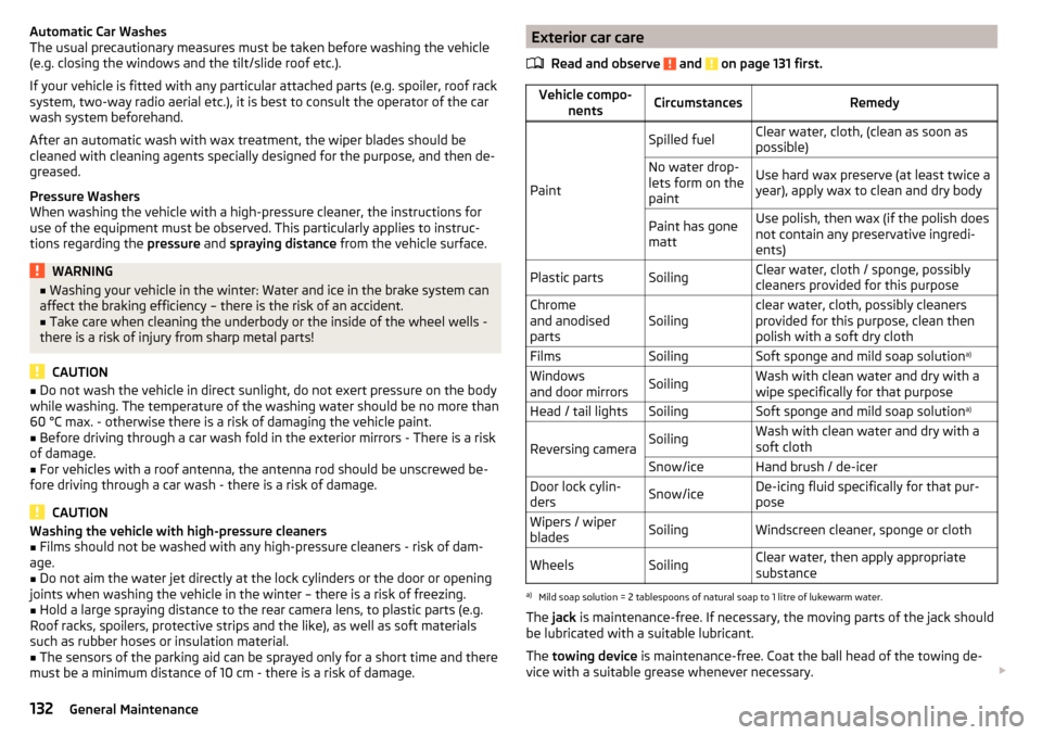
Automatic Car Washes
The usual precautionary measures must be taken before washing the vehicle
(e.g. closing the windows and the tilt/slide roof etc.).
If your vehicle is fitted with any particular attached parts (e.g. spoiler, roof rack system, two-way radio aerial etc.), it is best to consult the operator of the car
wash system beforehand.
After an automatic wash with wax treatment, the wiper blades should be
cleaned with cleaning agents specially designed for the purpose, and then de-
greased.
Pressure Washers
When washing the vehicle with a high-pressure cleaner, the instructions for
use of the equipment must be observed. This particularly applies to instruc-
tions regarding the pressure and spraying distance from the vehicle surface.WARNING■
Washing your vehicle in the winter: Water and ice in the brake system can
affect the braking efficiency – there is the risk of an accident.■
Take care when cleaning the underbody or the inside of the wheel wells -
there is a risk of injury from sharp metal parts!
CAUTION
■ Do not wash the vehicle in direct sunlight, do not exert pressure on the body
while washing. The temperature of the washing water should be no more than
60 °C max. - otherwise there is a risk of damaging the vehicle paint.■
Before driving through a car wash fold in the exterior mirrors - There is a risk
of damage.
■
For vehicles with a roof antenna, the antenna rod should be unscrewed be-
fore driving through a car wash - there is a risk of damage.
CAUTION
Washing the vehicle with high-pressure cleaners■Films should not be washed with any high-pressure cleaners - risk of dam-
age.■
Do not aim the water jet directly at the lock cylinders or the door or opening
joints when washing the vehicle in the winter – there is a risk of freezing.
■
Hold a large spraying distance to the rear camera lens, to plastic parts (e.g.
Roof racks, spoilers, protective strips and the like), as well as soft materials
such as rubber hoses or insulation material.
■
The sensors of the parking aid can be sprayed only for a short time and there
must be a minimum distance of 10 cm - there is a risk of damage.
Exterior car care
Read and observe
and on page 131 first.
Vehicle compo- nentsCircumstancesRemedy
Paint
Spilled fuelClear water, cloth, (clean as soon as
possible)No water drop-
lets form on the
paintUse hard wax preserve (at least twice a
year), apply wax to clean and dry bodyPaint has gone
mattUse polish, then wax (if the polish does
not contain any preservative ingredi-
ents)Plastic partsSoilingClear water, cloth / sponge, possibly
cleaners provided for this purposeChrome
and anodised
partsSoilingclear water, cloth, possibly cleaners
provided for this purpose, clean then
polish with a soft dry clothFilmsSoilingSoft sponge and mild soap solution a)Windows
and door mirrorsSoilingWash with clean water and dry with a
wipe specifically for that purposeHead / tail lightsSoilingSoft sponge and mild soap solution a)
Reversing cameraSoilingWash with clean water and dry with a
soft clothSnow/iceHand brush / de-icerDoor lock cylin-
dersSnow/iceDe-icing fluid specifically for that pur-
poseWipers / wiper
bladesSoilingWindscreen cleaner, sponge or clothWheelsSoilingClear water, then apply appropriate
substancea)
Mild soap solution = 2 tablespoons of natural soap to 1 litre of lukewarm water.
The jack is maintenance-free. If necessary, the moving parts of the jack should
be lubricated with a suitable lubricant.
The towing device is maintenance-free. Coat the ball head of the towing de-
vice with a suitable grease whenever necessary.
132General Maintenance
Page 165 of 196
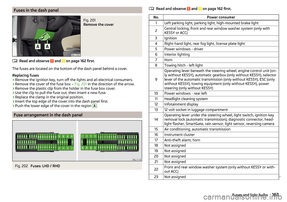
Fuses in the dash panelFig. 201
Remove the cover
Read and observe and on page 162 first.
The fuses are located on the bottom of the dash panel behind a cover.
Replacing fuses
›
Remove the ignition key, turn off the lights and all electrical consumers.
›
Remove the cover of the fuse box » Fig. 201 in the direction of the arrow.
›
Remove the plastic clip from the holder in the fuse box cover.
›
Use the clip to pull the fuse out, then insert a new fuse.
›
Replace the clamp in the original position.
›
Insert the top edge of the cover into the dash panel first.
›
Push the lower edge of the cover in the region
A
.
Fuse arrangement in the dash panel
Fig. 202
Fuses: LHD / RHD
Read and observe and on page 162 first.No.Power consumer1Left parking light, parking light, high-mounted brake light2Central locking, front and rear window washer system (only with
KESSY or ACC)3Ignition4Right-hand light, rear fog light, license plate light5Power windows - driver6Interior lighting7Horn8Towing hitch - left light
9
Operating lever beneath the steering wheel, engine control unit (on-
ly without KESSY), automatic gearbox (only without KESSY), selector
lever of the automatic transmission (only without KESSY), ESC (only
without KESSY), towing equipment (only without KESSY), power
steering (only without KESSY)10Power windows - rear left11Headlight cleaning system12Infotainment display1312 volt socket in luggage compartment14Operating lever under the steering wheel, light switch, ignition key
removal lock (automatic transmission), diagnostic connector, head-
light flasher, SmartGate, rain sensor, light sensor, reversing camera15Air conditioning, automatic transmission16Instrument cluster17Anti-theft alarm, horn18Not assigned19Not assigned20Not assigned21Not assigned22Front and rear window washer system (only without KESSY or with-
out ACC)23Not assigned 163Fuses and light bulbs
Page 167 of 196
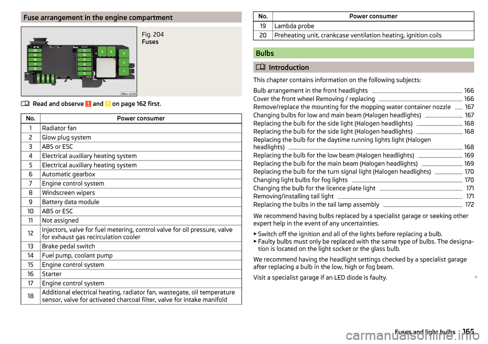
Fuse arrangement in the engine compartmentFig. 204
Fuses
Read and observe and on page 162 first.
No.Power consumer1Radiator fan2Glow plug system3ABS or ESC4Electrical auxiliary heating system5Electrical auxiliary heating system6Automatic gearbox7Engine control system8Windscreen wipers9Battery data module10ABS or ESC11Not assigned12Injectors, valve for fuel metering, control valve for oil pressure, valve
for exhaust gas recirculation cooler13Brake pedal switch14Fuel pump, coolant pump15Engine control system16Starter17Engine control system18Additional electrical heating, radiator fan, wastegate, oil temperature
sensor, valve for activated charcoal filter, valve for intake manifoldNo.Power consumer19Lambda probe20Preheating unit, crankcase ventilation heating, ignition coils
Bulbs
Introduction
This chapter contains information on the following subjects:
Bulb arrangement in the front headlights
166
Cover the front wheel Removing / replacing
166
Remove/replace the mounting for the mopping water container nozzle
167
Changing bulbs for low and main beam (Halogen headlights)
167
Replacing the bulb for the side light (Halogen headlights)
168
Replacing the bulb for the side light (Halogen headlights)
168
Replacing the bulb for the daytime running lights light (Halogen
headlights)
168
Replacing the bulb for the low beam (Halogen headlights)
169
Replacing the bulb for the main beam (Halogen headlights)
169
Replacing the bulb for the turn signal light (Halogen headlights)
170
Changing light bulbs for fog lights
170
Changing the bulb for the licence plate light
171
Removing/installing tail light
171
Replacing the bulbs in the tail lamp assembly
172
We recommend having bulbs replaced by a specialist garage or seeking other
expert help in the event of any uncertainties.
▶ Switch off the ignition and all of the lights before replacing a bulb.
▶ Faulty bulbs must only be replaced with the same type of bulbs. The designa-
tion is located on the light socket or the glass bulb.
We recommend having the headlight settings checked by a specialist garage after replacing a bulb in the low, high or fog beam.
Visit a specialist garage if an LED diode is faulty.
165Fuses and light bulbs