sensor SKODA FABIA 2016 3.G / NJ Owner's Manual
[x] Cancel search | Manufacturer: SKODA, Model Year: 2016, Model line: FABIA, Model: SKODA FABIA 2016 3.G / NJPages: 196, PDF Size: 31.86 MB
Page 20 of 196
WARNINGInformation about the front airbags■For the driver and front passenger, it is important to maintain a distance
of at least 25 cm to the steering wheel or the dashboard » Fig. 9 - A
, If you
do not keep this distance, it means that the airbag system cannot protect
you - There is a risk to life! The front seats and the head restraints must
always also be correctly adjusted to match the body size of the occupant.
■
It is essential to switch off the front passenger airbag if you are using a
child seat on the front passenger seat in which the child is carried with its
back facing the direction of travel » page 18, Airbag deactivation . If this is
not done, there is a risk of the child suffering severe or even fatal injuries if
the front passenger airbag is deployed.
■
No other persons, animals or objects should be placed in front of the oc-
cupants in the front seats in the deployment area of the front airbags.
■
The steering wheel and the surface of the dash panel on the passenger
side must not be plastered, covered or modified in any way. No parts (e.g.
cup holders, mobile phone mounts etc.) may be mounted near the airbag
installation points and in the airbag deployment area.
■
Never place objects on the surface of the dash panel on the passenger
side.
WARNINGInformation on side and head airbags■No objects (e.g. sun visors turned towards the windows) should be loca-
ted in the deployment area of the side and head airbags. No accessories
(e.g. cup holders etc.) should be fitted to the doors - risk of injury!■
Hang only light clothing on the hooks in the vehicle, do not leave any
heavy or sharp objects in the pockets. Do not use hangers to hang up
clothes.
■
The airbag system operates using pressure sensors located in the front
doors. For this reason, no adjustments may be carried out to the doors or
door panels (e.g. installation of additional loudspeakers). Further informa-
tion » page 128 .
■
No excessive force, e.g. through blows, kicks etc. should be applied to the
seat backrests - there is a risk of damage to the side airbags. The side air-
bags would not be deployed in such a case!
WARNING (Continued)■ Any seat or protective covers which you fit to the driver or front passen-
ger seats must only be of a type expressly authorised by ŠKODA AUTO. In
view of the fact that the airbag inflates out of the backrest of the seat, use
of non-approved seat or protective covers would considerably impair the
protective function of the side airbag.■
Any damage to the original seat covers or stitching at the installation
points for the side airbags should be immediately repaired by a specialist
company.
WARNINGInformation on the use of the airbag system■Any work on the airbag system, including the installation and removal of
system components due to other repair work (e.g. removal of the steering
wheel), must only be carried out by a specialist garage. Further information
» page 128 .■
No changes of any sort should be made to parts of the airbag system, the
front bumper or the bodywork.
■
Do not manipulate individual parts of the airbag system, as this might re-
sult in the airbag being deployed.
Airbag deactivation
Introduction
This chapter contains information on the following subjects:
Deactivating airbags
18
Deactivating the front passenger airbag
19
Deactivating airbags
The front passenger airbag can be switched off with the key-operated switch
» Fig. 10 on page 19 -
.
We recommend that you ask a ŠKODA Service Partner to switch off any other
airbags.
A warning light
indicates that the airbag has been deactivated » page 31.
18Safety
Page 36 of 196
GeneratorRead and observe
on page 29 first.
lights up – the battery is not being charged whilst the engine is running.
▶ As the vehicle battery during your journey, are all non-essential electrical
loads (e.g. Infotainment) must be switched off.
▶ You can drive on, exercising appropriate caution. Seek assistance from a spe-
cialist garage immediately.
CAUTION
If in addition to the light the light lights up while driving, stop driving -
risk of engine damage! Switch off the engine and seek assistance from a spe-
cialist garage.
Coolant
Read and observe
on page 29 first.
Coolant level too low
Illumi-
nates
ENGINE COOLANT PLEASE CHECK! Log book!ENGINE COOLANT PLEASE CHECK
▶ Stop the vehicle, switch off the engine, and allow the engine to cool down.
▶ Check the coolant level » page 141, Checking and refilling .
If the coolant level is within the specified range and the warning light lights
up again, then there may be a malfunction of the cooling fan.
▶ Switch off the ignition.
▶ Check the fuse for the radiator fan, replace if necessary.
If the coolant level and fan fuse are both OK but the warning light lights up
again,
stop driving!
▶ Seek help from a specialist garage.
Coolant temperature too high
Illumi-
nates
Engine overheat. Stop! Log book!ENGINE OVERHEAT STOP
▶ Stop the vehicle, switch off the engine, and allow the engine to cool down.
▶ Continue your journey only after the warning light has disappeared.
Engine oil pressure
Read and observe
on page 29 first.
flashes – the engine oil pressure is too low.
▶ Stop the vehicle, switch off the engine, and check the engine oil level.
▶ Even if the oil level is correct,
do not drive any further if the warning light
is flashing. Also do not leave the engine running at an idling speed.
▶ Seek help from a specialist garage.
CAUTION
If, under the given conditions, it is not possible to top up with engine oil, stop
driving - there is a risk of engine damage! Switch off the engine and seek as-
sistance from a specialist garage.
Engine oil level
Read and observe
on page 29 first.
Engine oil level too low
Illumi-
nates
Oil level: refill oil!ADD OIL
▶ Stop the vehicle, switch off the engine, and check the engine oil level, top up
if necessary.
The warning light will go out if the bonnet is left open for more than 30 sec-
onds. If the engine oil is not refilled, the warning light will come on again after
driving about 100 km.
Engine oil level too high
Illumi-
nates
Reduce oil level!OIL LEVEL TOO HIGH
▶ You can drive on, exercising appropriate caution. Seek assistance from a spe-
cialist garage immediately.
Fault on the engine oil level sensor
Illumi-
nates
Oil sensor: Workshop!OIL SENSOR WORKSHOP
▶ You can drive on, exercising appropriate caution. Seek assistance from a spe-
cialist garage immediately.
34Operation
Page 48 of 196
Unlocking/locking - KESSYFig. 31
Vehicle unlocking / vehicle locking
Read and observe
and on page 45 first.
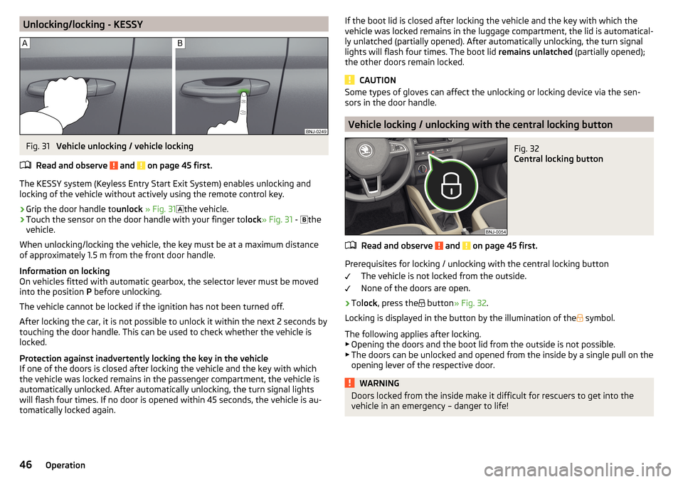
The KESSY system (Keyless Entry Start Exit System) enables unlocking and
locking of the vehicle without actively using the remote control key.
›
Grip the door handle to unlock » Fig. 31
the vehicle.
›
Touch the sensor on the door handle with your finger to
lock» Fig. 31 -
the
vehicle.
When unlocking/locking the vehicle, the key must be at a maximum distance
of approximately 1.5 m from the front door handle.
Information on locking
On vehicles fitted with automatic gearbox, the selector lever must be moved
into the position P before unlocking.
The vehicle cannot be locked if the ignition has not been turned off.
After locking the car, it is not possible to unlock it within the next 2 seconds by touching the door handle. This can be used to check whether the vehicle is
locked.
Protection against inadvertently locking the key in the vehicle
If one of the doors is closed after locking the vehicle and the key with which
the vehicle was locked remains in the passenger compartment, the vehicle is
automatically unlocked. After automatically unlocking, the turn signal lights
will flash four times. If no door is opened within 45 seconds, the vehicle is au-
tomatically locked again.
If the boot lid is closed after locking the vehicle and the key with which the vehicle was locked remains in the luggage compartment, the lid is automatical-
ly unlatched (partially opened). After automatically unlocking, the turn signal
lights will flash four times. The boot lid remains unlatched (partially opened);
the other doors remain locked.
CAUTION
Some types of gloves can affect the unlocking or locking device via the sen-
sors in the door handle.
Vehicle locking / unlocking with the central locking button
Fig. 32
Central locking button
Read and observe and on page 45 first.
Prerequisites for locking / unlocking with the central locking button
The vehicle is not locked from the outside.
None of the doors are open.
›
To lock , press the
button » Fig. 32 .
Locking is displayed in the button by the illumination of the
symbol.
The following applies after locking. ▶ Opening the doors and the boot lid from the outside is not possible.
▶ The doors can be unlocked and opened from the inside by a single pull on the
opening lever of the respective door.
WARNINGDoors locked from the inside make it difficult for rescuers to get into the
vehicle in an emergency – danger to life!46Operation
Page 57 of 196
WARNINGOnly turn on the main beam or the headlight flasher if other road users will
not be dazzled.
Automatic driving light control
Fig. 42
Light switch: AUTO position
Read and observe on page 53 first.
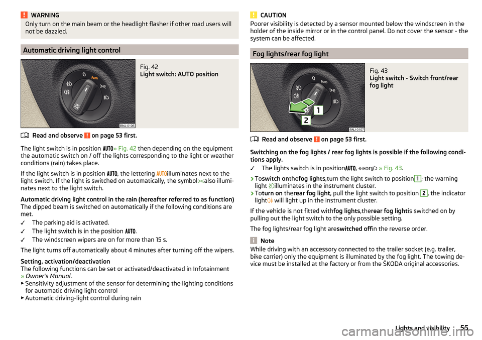
The light switch is in position
» Fig. 42 then depending on the equipment
the automatic switch on / off the lights corresponding to the light or weather
conditions (rain) takes place.
If the light switch is in position
, the lettering
illuminates next to the
light switch. If the light is switched on automatically, the symbol
also illumi-
nates next to the light switch.
Automatic driving light control in the rain (hereafter referred to as function)
The dipped beam is switched on automatically if the following conditions are
met.
The parking aid is activated.
The light switch is in the position
.
The windscreen wipers are on for more than 15 s.
The light turns off automatically about 4 minutes after turning off the wipers.
Setting, activation/deactivation
The following functions can be set or activated/deactivated in Infotainment
» Owner's Manual .
▶ Sensitivity adjustment of the sensor for determining the lighting conditions
for automatic driving light control
▶ Automatic driving-light control during rain
CAUTIONPoorer visibility is detected by a sensor mounted below the windscreen in the
holder of the inside mirror or in the control panel. Do not cover the sensor - the
system can be affected.
Fog lights/rear fog light
Fig. 43
Light switch - Switch front/rear
fog light
Read and observe on page 53 first.
Switching on the fog lights / rear fog lights is possible if the following condi-
tions apply.
The lights switch is in position
,
or
» Fig. 43 .
›
Toswitch on thefog lights ,turn the light switch to position
1
; the warning
light
illuminates in the instrument cluster.
›
To turn on therear fog light , pull the light switch to position
2
, the indicator
light
will light up in the instrument cluster.
If the vehicle is not fitted with fog lights,therear fog light is switched on by
pulling out the light switch to the only possible setting.
The fog lights/rear fog light are switched offin the reverse order.
Note
While driving with an accessory connected to the trailer socket (e.g. trailer,
bike carrier) only the equipment is illuminated by the fog light. The towing de-
vice must be installed at the factory or from the ŠKODA original accessories.55Lights and visibility
Page 58 of 196
Fog lights with the CORNER functionRead and observe
on page 53 first.
The CORNER function automatically switches on the fog lights on the respec-tive side of the vehicle (e.g. when cornering), if the following conditions are
met.
The turn signal is switched on or the front wheels are turned sharply 1)
.
The vehicle speed is below 40 km/h.
The low beam is switched on.
The fog lights are not switched on.
The two fog lights are switched on when you shift into the reverse gear.
COMING HOME / LEAVING HOME
Read and observe
on page 53 first.
The function COMING HOME ensures that the vehicle's environment is illumi-
nated after switching off the ignition and opening the driver's door.
The function LEAVING HOME ensures that the vehicle's environment is illumi-
nated after unlocking the vehicle with the radio remote control unit.
The function switches the light on only if there is poorer visibility and the light
switch is in the position .
The two functions can be activated/deactivated and set in Infotainment
» Owner's Manual Infotainment .
CAUTION
■
Poorer visibility is detected by a sensor mounted below the windscreen in
the holder of the inside mirror or in the control panel. Do not cover the sensor -
the system can be affected.■
If this option is always enabled, then the battery is heavily loaded.
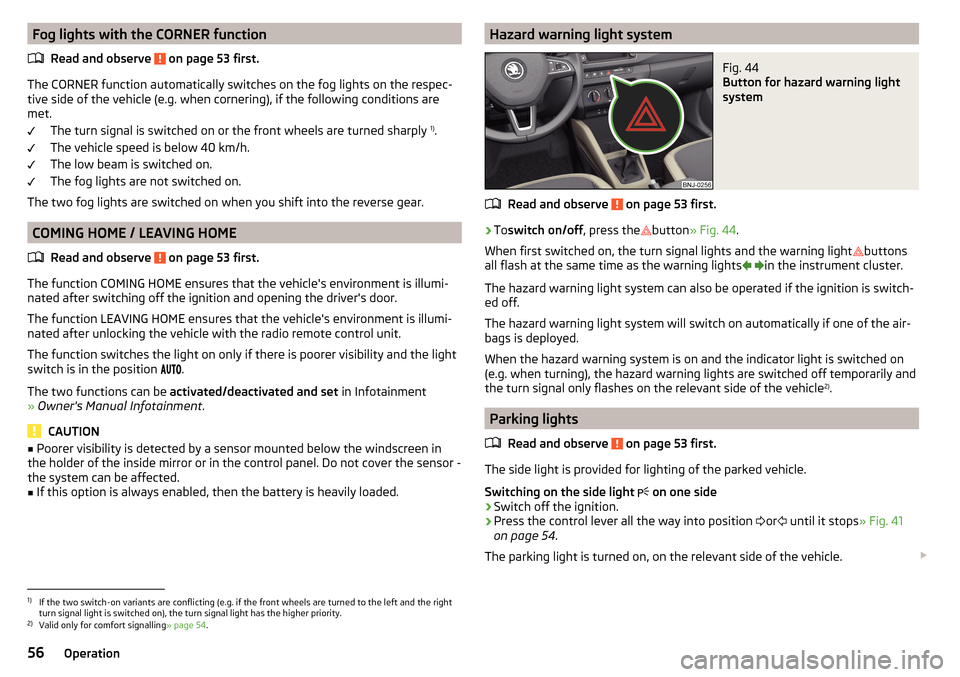
Hazard warning light systemFig. 44
Button for hazard warning light
system
Read and observe on page 53 first.
›
To switch on/off , press the
button
» Fig. 44 .
When first switched on, the turn signal lights and the warning light buttons
all flash at the same time as the warning lights
in the instrument cluster.
The hazard warning light system can also be operated if the ignition is switch-
ed off.
The hazard warning light system will switch on automatically if one of the air-
bags is deployed.
When the hazard warning system is on and the indicator light is switched on
(e.g. when turning), the hazard warning lights are switched off temporarily and
the turn signal only flashes on the relevant side of the vehicle 2)
.
Parking lights
Read and observe
on page 53 first.
The side light is provided for lighting of the parked vehicle.
Switching on the side light on one side
›
Switch off the ignition.
›
Press the control lever all the way into position
or
until it stops
» Fig. 41
on page 54 .
The parking light is turned on, on the relevant side of the vehicle.
1)
If the two switch-on variants are conflicting (e.g. if the front wheels are turned to the left and the right
turn signal light is switched on), the turn signal light has the higher priority.
2)
Valid only for comfort signalling » page 54.
56Operation
Page 63 of 196
Rear view mirror
Introduction
This chapter contains information on the following subjects:
Interior mirror dimming
61
Mirrors
61WARNINGExterior mirrors increase the field of view, however, they make objects ap-
pear smaller and further away. Therefore, use the interior mirror whenever
possible for assessing the distances to the vehicles following behind.
Interior mirror dimming
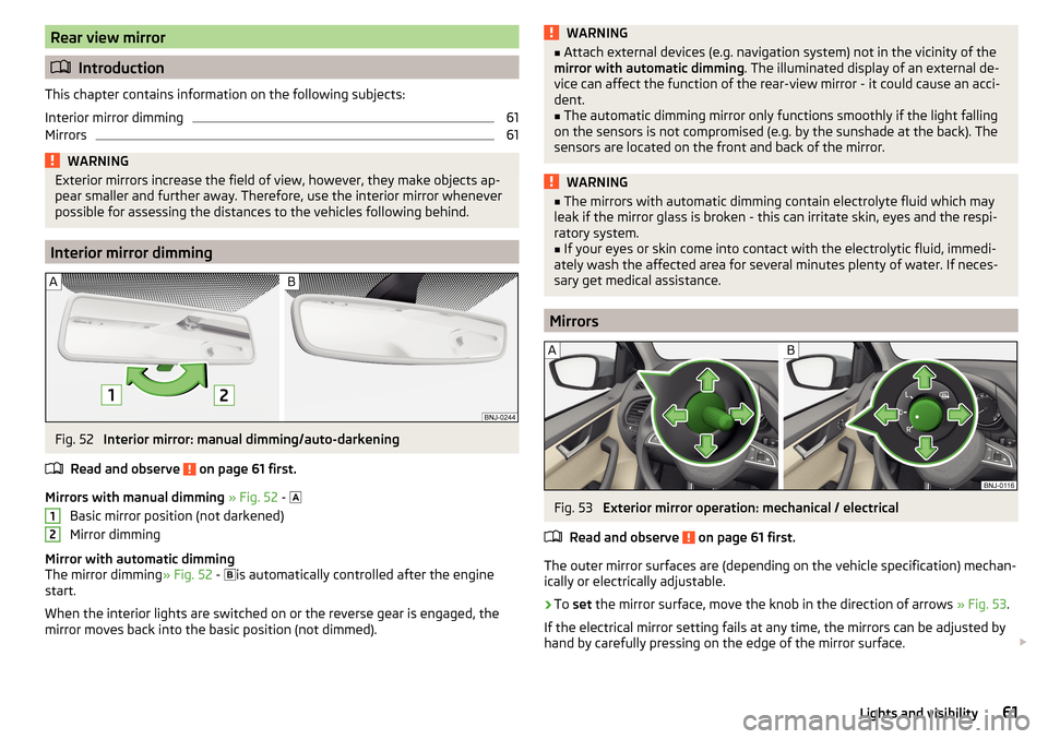
Fig. 52
Interior mirror: manual dimming/auto-darkening
Read and observe
on page 61 first.
Mirrors with manual dimming » Fig. 52 -
Basic mirror position (not darkened)
Mirror dimming
Mirror with automatic dimming
The mirror dimming » Fig. 52 -
is automatically controlled after the engine
start.
When the interior lights are switched on or the reverse gear is engaged, the
mirror moves back into the basic position (not dimmed).
12WARNING■ Attach external devices (e.g. navigation system) not in the vicinity of the
mirror with automatic dimming . The illuminated display of an external de-
vice can affect the function of the rear-view mirror - it could cause an acci-
dent.■
The automatic dimming mirror only functions smoothly if the light falling
on the sensors is not compromised (e.g. by the sunshade at the back). The
sensors are located on the front and back of the mirror.
WARNING■ The mirrors with automatic dimming contain electrolyte fluid which may
leak if the mirror glass is broken - this can irritate skin, eyes and the respi-
ratory system.■
If your eyes or skin come into contact with the electrolytic fluid, immedi-
ately wash the affected area for several minutes plenty of water. If neces-
sary get medical assistance.
Mirrors
Fig. 53
Exterior mirror operation: mechanical / electrical
Read and observe
on page 61 first.
The outer mirror surfaces are (depending on the vehicle specification) mechan-
ically or electrically adjustable.
›
To set the mirror surface, move the knob in the direction of arrows » Fig. 53.
If the electrical mirror setting fails at any time, the mirrors can be adjusted by
hand by carefully pressing on the edge of the mirror surface.
61Lights and visibility
Page 89 of 196
Climatronic (automatic air conditioning)Fig. 112
Controls the Climatronic
Read and observe
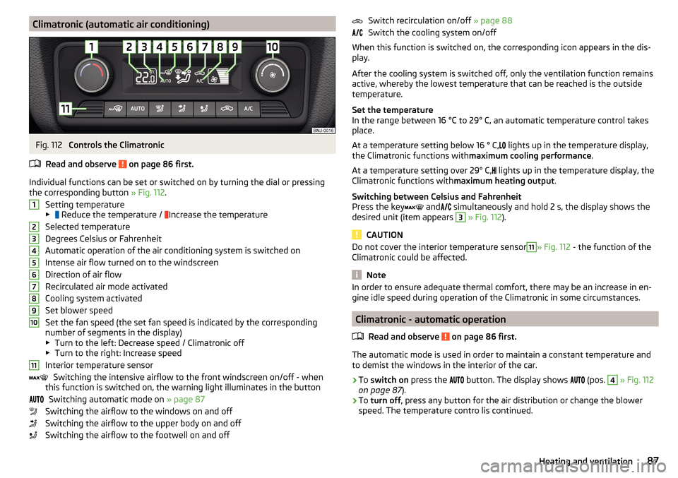
on page 86 first.
Individual functions can be set or switched on by turning the dial or pressing the corresponding button » Fig. 112.
Setting temperature
▶ Reduce the temperature /
Increase the temperature
Selected temperature
Degrees Celsius or Fahrenheit
Automatic operation of the air conditioning system is switched on
Intense air flow turned on to the windscreen
Direction of air flow
Recirculated air mode activated
Cooling system activated
Set blower speed
Set the fan speed (the set fan speed is indicated by the corresponding
number of segments in the display)
▶ Turn to the left: Decrease speed / Climatronic off
▶ Turn to the right: Increase speed
Interior temperature sensor Switching the intensive airflow to the front windscreen on/off - when
this function is switched on, the warning light illuminates in the button
Switching automatic mode on » page 87
Switching the airflow to the windows on and off
Switching the airflow to the upper body on and off
Switching the airflow to the footwell on and off
1234567891011Switch recirculation on/off » page 88
Switch the cooling system on/off
When this function is switched on, the corresponding icon appears in the dis-
play.
After the cooling system is switched off, only the ventilation function remains
active, whereby the lowest temperature that can be reached is the outside
temperature.
Set the temperature
In the range between 16 °C to 29° C, an automatic temperature control takes
place.
At a temperature setting below 16 ° C, lights up in the temperature display,
the Climatronic functions with maximum cooling performance .
At a temperature setting over 29° C, lights up in the temperature display, the
Climatronic functions with maximum heating output.
Switching between Celsius and Fahrenheit
Press the key and
simultaneously and hold 2 s, the display shows the
desired unit (item appears 3
» Fig. 112 ).
CAUTION
Do not cover the interior temperature sensor11» Fig. 112 - the function of the
Climatronic could be affected.
Note
In order to ensure adequate thermal comfort, there may be an increase in en-
gine idle speed during operation of the Climatronic in some circumstances.
Climatronic - automatic operation
Read and observe
on page 86 first.
The automatic mode is used in order to maintain a constant temperature andto demist the windows in the interior of the car.
›
To switch on press the
button. The display shows
(pos.
4
» Fig. 112
on page 87 ).
›
To turn off , press any button for the air distribution or change the blower
speed. The temperature contro lis continued.
87Heating and ventilation
Page 102 of 196
The following instructions must be observed if vehicle damage is to be avoided
when driving through water (e.g. flooded roads).›
Therefore, always determine the depth of the water before driving through
water. The water level must not go above the web of the lower beam
» Fig. 124 .
›
Drive at no more than walking pace, otherwise a wave may form in front of
the vehicle, which could cause the water to enter into the vehicle’s systems
(e.g. the air intake system for the engine).
›
Never stop in the water, do not reverse and do not switch the engine off.
CAUTION
■ If water gets into the vehicle’s systems (e.g. the air intake system for the en-
gine) it can cause serious damage to the vehicle!■
Oncoming vehicles can generate water waves which can exceed the permis-
sible water level for your vehicle.
■
Do not drive through salt water, as the salt can cause corrosion. A vehicle
coming into contact with salt water is to be thoroughly rinsed with fresh wa-
ter.
Assist systems
General information
Introduction
This chapter contains information on the following subjects:
Radar sensor
100WARNING■ The assistance systems only serve to support and do not relieve the driv-
er of the responsibility for driving the vehicle.■
The increased safety provision, as well as the increased occupant protec-
tion provided by the assistance systems must not tempt you to take risks -
risk of accident!
■
Adjust the speed and driving style to the current visibility, weather, road
and traffic conditions.
■
The assistance systems have physical and system-related limitations. For
this reason, the driver may experience some undesired or delayed system
responses in certain situations. You should therefore always be alert and
ready to intervene!
■
Only enable, disable or set the assistance systems so that you have the
car fully under control in every traffic situation - risk of accident!
Radar sensor
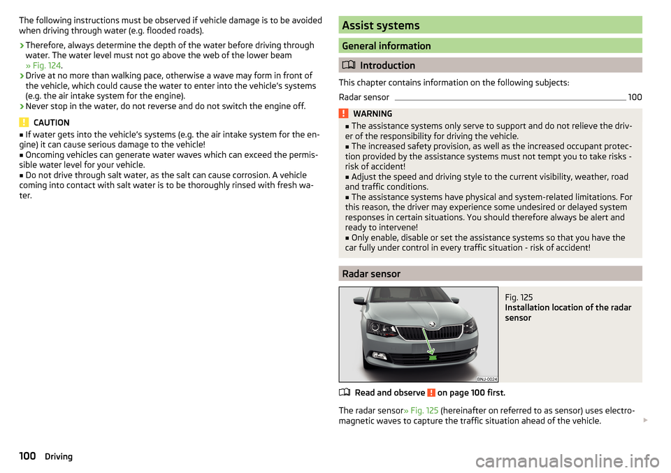
Fig. 125
Installation location of the radar
sensor
Read and observe on page 100 first.
The radar sensor » Fig. 125 (hereinafter on referred to as sensor) uses electro-
magnetic waves to capture the traffic situation ahead of the vehicle.
100Driving
Page 103 of 196
The sensor is part of the ACC» page 110 and Front Assist » page 114systems.
The sensor function may be impaired in the events of one of the following. ▶ The sensor cover is soiled (e.g. with mud, snow etc.).
▶ The area in front of and around the sensor cover is obscured (e.g. by labels,
auxiliary headlights etc.).
▶ When visibility is poor, (e.g. fog, heavy rain, thick snowfall).
If the sensor is covered or dirty, the corresponding message appears in the in-
strument cluster display for the ACC system » page 114, Malfunctions or Front
Assist system » page 116, Malfunctions .WARNING■
If you suspect that the sensor is damaged, deactivate the ACC system and
Front Assist system » page 111, » page 116 . Have the sensor checked by a
specialist garage.■
A collision or damage in the front or lower area of the vehicle could affect
the sensor function - there is risk of accident! Have the sensor checked by
a specialist garage.
■
Do not cover the area in front of and around the sensor cover. This can
lead to impaired function of the sensor - risk of accidents!
CAUTION
Remove the snow with a brush and the ice with a solvent-free de-icer.
Braking and stabilisation systems
Introduction
This chapter contains information on the following subjects:
Stability Control (ESC)
101
Anti-lock braking system (ABS)
101
Engine drag torque control (MSR)
101
Traction control (TCS)
102
Electronic differential lock (EDL and XDS)
102
Brake Assist (HBA)
102
Hill Start Assist (HHC)
102
Multi collision brake (MCB)
103
The brake and stabilization systems are automatically activated each time the
ignition is switched on, unless otherwise indicated.
The error display is in Chapter » page 28, Warning lights .WARNINGThe general information relating to the use of assistance systems must be
observed » page 100, in section Introduction .
Stability Control (ESC)
Read and observe
on page 101 first.
The ESC improves vehicle stability when driving at the limit (e.g. if the vehiclestarts to skid) by braking individual wheels to maintain the desired direction.
If there is a TCS intervention, the indicator light flashes in the instrument
cluster.
Anti-lock braking system (ABS)
Read and observe
on page 101 first.
ABS prevents the wheels locking when braking. Thereby, it helps the driver to
maintain control of the vehicle.
The intervention of the ABS is noticeable from the pulsating movements of
the brake pedal which is accompanied by noises.
When the ABS system is active, do not pump the brakes or lift off the brake
pedal.
Engine drag torque control (MSR)
Read and observe
on page 101 first.
MSR counteracts the tendency of the drive wheels to lock during downshifts
or sudden deceleration (e.g. on icy or an otherwise slippery road surface).
If the drive wheels should lock, then the engine speed is automatically in-
creased. This reduces the braking effect of the engine and the wheels can ro-
tate freely again.
101Assist systems
Page 105 of 196

Multi collision brake (MCB)Read and observe
on page 101 first.
MCB helps to decrease speed after a collision by means of automatic braking
interventions and to stabilise the vehicle. This reduces the risk of a subse-
quent crash due to uncontrolled vehicle movement.
The automatic brake interventions can take place only if the following condi-
tions are met.
There was a front, side and rear-end collision of a certain severity.
The impact speed was greater than approx. 10 km/h.
The brakes, the ESL and other required electrical systems remain function-
al after impact.
The accelerator pedal is not actuated.
Parking aid (ParkPilot)
Introduction
This chapter contains information on the following subjects:
Function
103
Display in the Infotainment display
104
Activation / deactivation
105
Automatic system activation when moving forward
105
The parking aid (hereinafter referred to as "system") draws attention to obsta-
cles in the vicinity of the vehicle via acoustic signals or on the Infotainment
display when manoeuvring.
WARNING■ The general information relating to the use of assistance systems must
be observed » page 100, in section Introduction .■
Moving persons or objects may not be recognised by the system sensors.
■
Under certain circumstances, surfaces of certain objects and types of
clothing cannot reflect the system signals. There is a danger that such ob-
jects or people may not be recognised by the system sensors.
WARNING (Continued)■ External noise sources may affect the signals of the system sensors.
There is a danger that obstacles may not be recognised by the system sen-
sors.■
Before reversing, you should satisfy yourself that there are no small ob-
stacle, such as a rock, thin post etc., in front or behind your vehicle. Such
obstacles may not be recognised by the system sensors.
CAUTION
■ Keep the system sensors » Fig. 127 on page 103 clean, snow-and ice-free
and do not cover with any objects of any kind, otherwise the system function-
ing may be impaired.■
In adverse weather conditions (heavy rain, water vapour, very low or high
temperatures, etc.), the functioning of the system may be impaired - “incorrect
recognition of obstacles”.
■
Accessories additionally installed on the vehicle rear, such as bicycle carriers,
can impair the system function.
Function
Fig. 127
Installation location of the sensors on the left side of the vehicle:
front / rear
103Assist systems