display SKODA KODIAQ 2016 1.G Owner's Guide
[x] Cancel search | Manufacturer: SKODA, Model Year: 2016, Model line: KODIAQ, Model: SKODA KODIAQ 2016 1.GPages: 344, PDF Size: 58.96 MB
Page 49 of 344
There is the option to show/hide the representation of the menu items of the
multifunction display in Infotainment in the instrument cluster display by tap-
ping
→
→
Instrument cluster
and reset the journey data.
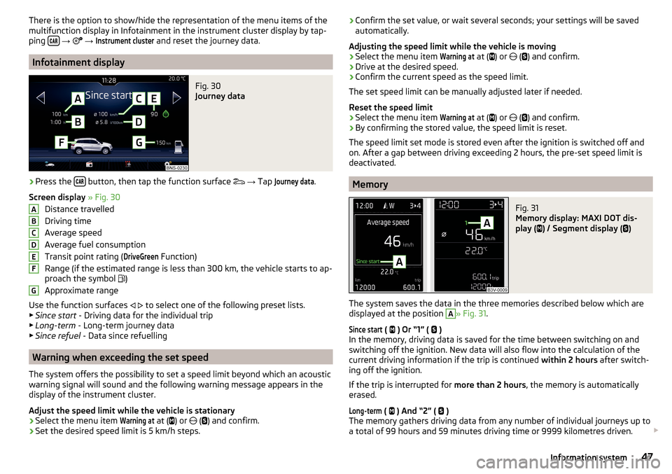
Infotainment display
Fig. 30
Journey data
›
Press the button, then tap the function surface
→ Tap
Journey data
.
Screen display » Fig. 30
Distance travelled
Driving time
Average speed
Average fuel consumption
Transit point rating (
DriveGreen
Function)
Range (if the estimated range is less than 300 km, the vehicle starts to ap-
proach the symbol )
Approximate range
Use the function surfaces
to select one of the following preset lists.
▶ Since start - Driving data for the individual trip
▶ Long-term - Long-term journey data
▶ Since refuel - Data since refuelling
Warning when exceeding the set speed
The system offers the possibility to set a speed limit beyond which an acoustic
warning signal will sound and the following warning message appears in the
display of the instrument cluster.
Adjust the speed limit while the vehicle is stationary
›
Select the menu item
Warning at
at ( ) or
(
) and confirm.
›
Set the desired speed limit is 5 km/h steps.
ABCDEFG› Confirm the set value, or wait several seconds; your settings will be saved
automatically.
Adjusting the speed limit while the vehicle is moving›
Select the menu item
Warning at
at (
) or
(
) and confirm.
›
Drive at the desired speed.
›
Confirm the current speed as the speed limit.
The set speed limit can be manually adjusted later if needed.
Reset the speed limit
›
Select the menu item
Warning at
at (
) or
(
) and confirm.
›
By confirming the stored value, the speed limit is reset.
The speed limit set mode is stored even after the ignition is switched off and
on. After a gap between driving exceeding 2 hours, the pre-set speed limit is
deactivated.
Memory
Fig. 31
Memory display: MAXI DOT dis-
play (
) / Segment display (
)
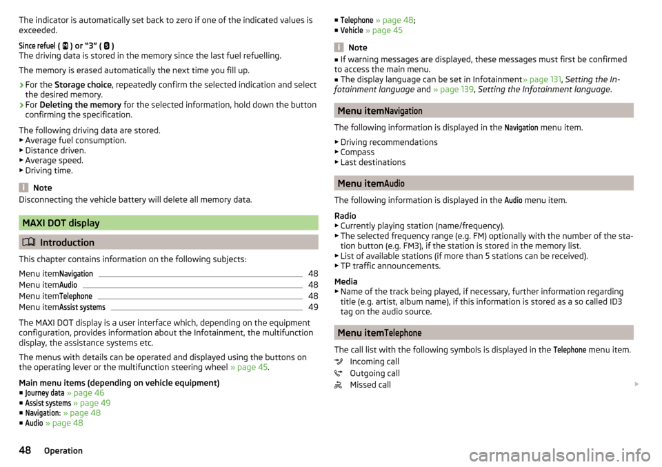
The system saves the data in the three memories described below which are
displayed at the position
A
» Fig. 31 .
Since start
(
) Or “1” (
)
In the memory, driving data is saved for the time between switching on and
switching off the ignition. New data will also flow into the calculation of the
current driving information if the trip is continued within 2 hours after switch-
ing off the ignition.
If the trip is interrupted for more than 2 hours, the memory is automatically
erased.
Long-term
( ) And “2” (
)
The memory gathers driving data from any number of individual journeys up to
a total of 99 hours and 59 minutes driving time or 9999 kilometres driven.
47Information system
Page 50 of 344
The indicator is automatically set back to zero if one of the indicated values is
exceeded.Since refuel
(
) or “3” (
)
The driving data is stored in the memory since the last fuel refuelling.
The memory is erased automatically the next time you fill up.
›
For the Storage choice , repeatedly confirm the selected indication and select
the desired memory.
›
For Deleting the memory for the selected information, hold down the button
confirming the specification.
The following driving data are stored. ▶ Average fuel consumption.
▶ Distance driven.
▶ Average speed.
▶ Driving time.
Note
Disconnecting the vehicle battery will delete all memory data.
MAXI DOT display
Introduction
This chapter contains information on the following subjects:
Menu item
Navigation48
Menu item
Audio48
Menu item
Telephone48
Menu item
Assist systems49
The MAXI DOT display is a user interface which, depending on the equipment
configuration, provides information about the Infotainment, the multifunction
display, the assistance systems etc.
The menus with details can be operated and displayed using the buttons on
the operating lever or the multifunction steering wheel » page 45.
Main menu items (depending on vehicle equipment) ■
Journey data
» page 46
■
Assist systems
» page 49
■
Navigation:
» page 48
■
Audio
» page 48
■Telephone » page 48 ;
■Vehicle
» page 45
Note
■
If warning messages are displayed, these messages must first be confirmed
to access the main menu.■
The display language can be set in Infotainment » page 131, Setting the In-
fotainment language and » page 139 , Setting the Infotainment language .
Menu item
Navigation
The following information is displayed in the
Navigation
menu item.
▶ Driving recommendations
▶ Compass
▶ Last destinations
Menu item
Audio
The following information is displayed in the
Audio
menu item.
Radio
▶ Currently playing station (name/frequency).
▶ The selected frequency range (e.g. FM) optionally with the number of the sta-
tion button (e.g. FM3), if the station is stored in the memory list.
▶ List of available stations (if more than 5 stations can be received).
▶ TP traffic announcements.
Media
▶ Name of the track being played, if necessary, further information regarding
title (e.g. artist, album name), if this information is stored as a so called ID3
tag on the audio source.
Menu item
Telephone
The call list with the following symbols is displayed in the
Telephone
menu item.
Incoming call
Outgoing call
Missed call
48Operation
Page 51 of 344
Symbols in the displayCharge status of the telephone battery 1)
Signal strength 1 )
A telephone is connected to the unit
Missed calls (if there are several missed calls, the number of calls is shown
next to the symbol)
Switch-off microphone
Menu item
Assist systems
The following systems are activated/deactivated in the
Assist systems
menu
item.
▶ Front Assist
▶ Lane Assist
▶ Rear Traffic Alert
▶ Assist system for blind spot monitoring
Service interval display
Introduction
This chapter contains information on the following subjects:
Displaying the distance and days until the next service interval
49
Service messages
49
Resetting the service interval display
50
The service interval display shows the kilometres or days until the next service
event.
Information regarding the service intervals » page 268.
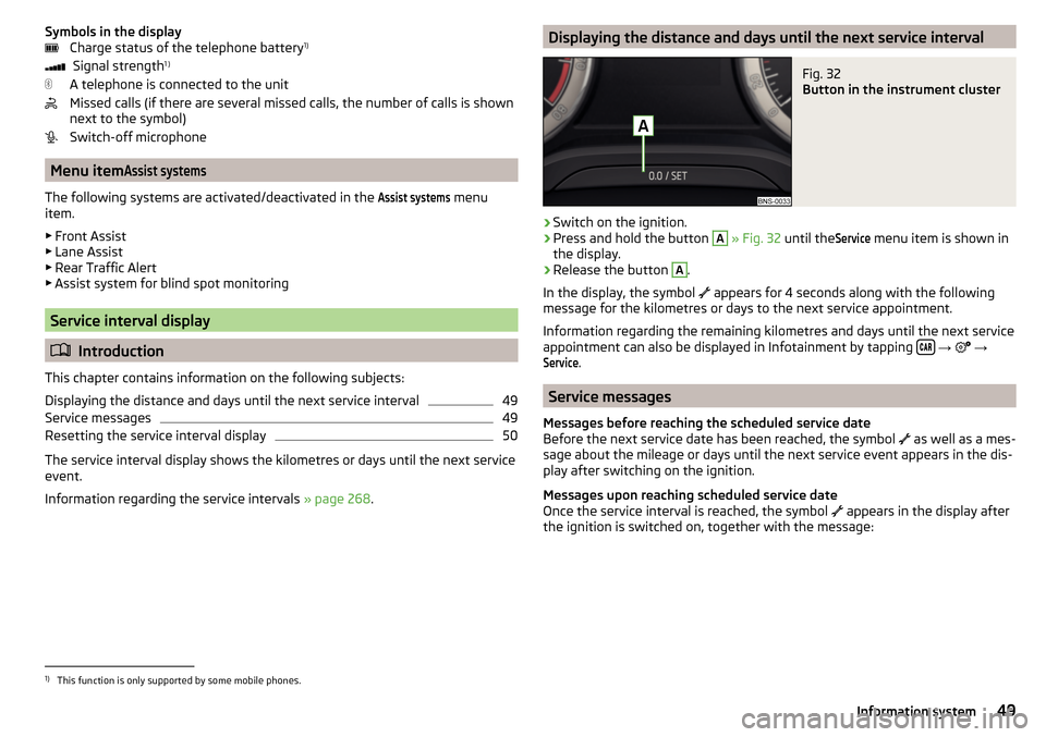
Displaying the distance and days until the next service intervalFig. 32
Button in the instrument cluster
›
Switch on the ignition.
›
Press and hold the button
A
» Fig. 32 until the
Service
menu item is shown in
the display.
›
Release the button
A
.
In the display, the symbol appears for 4 seconds along with the following
message for the kilometres or days to the next service appointment.
Information regarding the remaining kilometres and days until the next service appointment can also be displayed in Infotainment by tapping
→
→
Service
.
Service messages
Messages before reaching the scheduled service date
Before the next service date has been reached, the symbol as well as a mes-
sage about the mileage or days until the next service event appears in the dis-
play after switching on the ignition.
Messages upon reaching scheduled service date
Once the service interval is reached, the symbol appears in the display after
the ignition is switched on, together with the message:
1)
This function is only supported by some mobile phones.
49Information system
Page 52 of 344
Resetting the service interval display
We recommend that the display reset is completed by a specialist garage.
We recommend that you do not reset the service interval display yourself. In-
correctly setting the service interval display could cause problems to the vehi-
cle.
Variable service interval
For vehicles with variable service intervals, after resetting the oil change serv-
ice display in a specialist garage, the values of the new service interval are dis-
played, which are based on the previous operating conditions of the vehicle.
These values are then continuously matched according to the actual operating
conditions of the vehicle.
Personalization
Introduction
This chapter contains information on the following subjects:
Operating principle
50
Overview of some personalized functions
51
Setting the personalization
51
Thanks to the personalisation, more drivers have the opportunity to use a ve-
hicle with individually set system functions by means of a user account which
is assigned to the respective vehicle key.
WARNINGMake all adjustments when the vehicle is stationary - otherwise there is
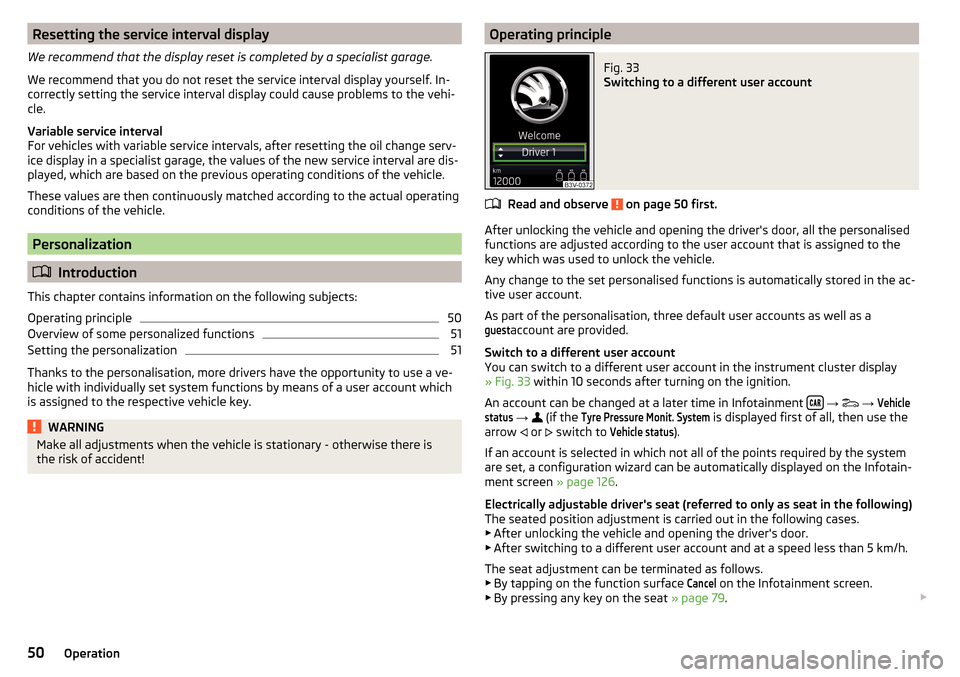
the risk of accident!Operating principleFig. 33
Switching to a different user account
Read and observe on page 50 first.
After unlocking the vehicle and opening the driver's door, all the personalised
functions are adjusted according to the user account that is assigned to the
key which was used to unlock the vehicle.
Any change to the set personalised functions is automatically stored in the ac- tive user account.
As part of the personalisation, three default user accounts as well as a
guest
account are provided.
Switch to a different user account
You can switch to a different user account in the instrument cluster display
» Fig. 33 within 10 seconds after turning on the ignition.
An account can be changed at a later time in Infotainment
→
→
Vehiclestatus
→
(if the
Tyre Pressure Monit. System
is displayed first of all, then use the
arrow or
switch to
Vehicle status
).
If an account is selected in which not all of the points required by the system
are set, a configuration wizard can be automatically displayed on the Infotain-
ment screen » page 126.
Electrically adjustable driver's seat (referred to only as seat in the following)
The seated position adjustment is carried out in the following cases. ▶ After unlocking the vehicle and opening the driver's door.
▶ After switching to a different user account and at a speed less than 5 km/h.
The seat adjustment can be terminated as follows.
▶ By tapping on the function surface
Cancel
on the Infotainment screen.
▶ By pressing any key on the seat » page 79.
50Operation
Page 53 of 344
NoteVehicles with the personalisation function are provided with three vehicle
keys.
Overview of some personalized functions
Read and observe
on page 50 first.
▶Driving mode - the last selected mode, mode setting
Individual
▶Setting the electrically adjustable driver's seat.
▶ Exterior mirror adjustment.
▶ Assistance systems - Lane Assist, parking aid (Park Pilot).
▶ Light - ambient lighting, convenience turn signal, COMING HOME / LEAVING
HOME.
▶ Climatronic - temperature in each individual area, fan speed, recirculation
mode.
▶ Infotainment settings - brightness level of the screen, keyboard arrange-
ment.
▶ Radio - sound settings, station sorting.
▶ Media - shuffle / repeat title, selected video format.
▶ Voice control - acoustic signals.
▶ Navigation - home address, alternative routes, recommended route, remind-
er of the lack of fuel.
Note
The scope of the personalisation functions is dependent on the type of Info-
tainment package.
Setting the personalization
Read and observe
on page 50 first.
›
On Infotainment, press the button, then tap the function surface
→
Personalisation
.
The following menu items are displayed.
Personalisation
Active
- activate/deactivate the personalisation
Select a user account
A list of user accounts with the option to manage user accounts and to switch
to another account.
■ - Account management with the following options:
■Rename user account
- rename the user account (not applicable to the
Guest
account)
■
Copy settings to another account
- copy the settings of an active user account to
another user account
■
Reset user account
- reset the selected user account to factory settings
Adjusting ■
Key assignment:
- options for assigning the vehicle key to the user account:
■
Manual
- detected vehicle key must be assigned to the active user account
manually
■
Automatic
- detected vehicle key automatically assigned to a different ac-
count of the active user account
■
Assign vehicle key to current user account
- manual assignment of the detected ve-
hicle key to the active user account - follow the instructions on the Infotain-
ment screen
■
Reset all
- reset the personalisation and the user accounts to factory settings
51Information system
Page 54 of 344
Unlocking and opening
Unlocking and locking
Introduction
This chapter contains information on the following subjects:
Unlocking/locking with the remote control key
52
Remove KESSY emergency key
53
Locking / unlocking - KESSY
53
Locking/unlocking the vehicle with the central locking button
54
SafeLock
54
Individual settings
54
Opening / closing door
55
Door edge protection
55
Child safety lock
56
Malfunctions
57
The vehicle is equipped with a central locking system which makes it possible
to unlock / lock all the doors, the fuel filler flap and boot lid simultaneously.
The door unlocking can be adjusted individually » page 54.
The unlocking of the vehicle is displayed by the turn signal lights flashing
twice.
If you unlock the vehicle and do not open a door or the boot lid within the next
45 seconds, the vehicle will lock again automatically.
The locking of the vehicle is displayed by the turn signal lights flashing once.
If the driver's door has been opened, the vehicle cannot be locked.
If the doors or the boot lid remain open after the vehicle has been locked, the turn signal lights do not flash until they have been closed.
WARNING■ Never leave the key in the vehicle when you exit the vehicle. Unauthor-
ized persons (e.g. children) could lock the car, turn on the ignition or start
the engine - there is a danger of injury and accidents!■
When leaving the vehicle, never leave people who are not completely in-
dependent, such as children, unattended in the vehicle. These individuals
might not be able to leave the vehicle on their own or to help themselves.
Can be fatal at very high or very low temperatures!
CAUTION
■ Each key contains electronic components; therefore it must be protected
against moisture and severe shocks.■
Keep the keyway clean. Impurities (textile fibres, dust etc.) have a negative
effect on the functionality of the locking cylinder and ignition lock.
Unlocking/locking with the remote control key
Fig. 34
Key with fold/out key bit/KESSY key
Read and observe
and on page 52 first.
Description of the key » Fig. 34
Unlock button
Lock button
Depending on equipment fitted:
▶ Unlock/unlatch the boot lid (vehicles fitted with manual folding opera-
tion)
▶ Open/close/ the boot lid Stop movement of the boot lid (vehicles with
electric folding operation)
52Operation
Page 56 of 344
If the boot lid is closed after locking the vehicle and the key with which the
vehicle was locked remains in the luggage compartment, the lid is automatical-
ly unlatched (partially opened). After automatically unlocking, the turn signal
lights will flash four times. The boot lid remains unlatched (partially opened);
the other doors remain locked.
CAUTION
Some types of gloves can affect the unlocking or locking device via the sen-
sors in the door handle.
Locking/unlocking the vehicle with the central locking button
Fig. 37
Central locking button
Read and observe and on page 52 first.
Conditions for the locking/unlocking using the central locking button.
The vehicle is not locked from the outside.
None of the doors are open.
›
To lock , press the
button » Fig. 37 .
Locking is displayed in the button by the illumination of the symbol
in the
button.
The following applies after locking. ▶ Opening the doors and the boot lid from the outside is not possible.
▶ The doors can be unlocked and opened from the inside by a single pull on the
opening lever of the respective door.
WARNINGDoors locked from the inside make it difficult for rescuers to get into the
vehicle in an emergency – risk to life!SafeLock
Read and observe
and on page 52 first.
SafeLock prevents the doors from behind opened from inside as well as win-
dow operation. This makes it more difficult for anyone to break into the vehi-
cle.
Switching on
SafeLock switches on when the vehicle is locked.
This function is pointed out by the following message on the display of the in-
strument cluster after the ignition is switched off.
SAFE interlock. note! Log book!CHECK SAFELOCK
Switch-on display
With the activated SafeLock, the warning light in the driver´s door flashes for 2
seconds in rapid succession, this then starts to flash at longer intervals.
Switching off ▶ By locking twice within 2 seconds.
▶ or: by deactivating the interior monitor and the towing protection
» page 58 .
The warning light in the driver´s door flashes fast for about 2 seconds, goes
out and starts to flash at longer intervals after about 30 seconds.
If the vehicle is locked and the safe securing system is switched off, the door
can be opened separately from the inside by a single pull on opening lever.
The safelock switches on the next time the vehicle is locked.
WARNINGIf the car is locked and the safe securing system activated, no people must
remain in the car as it will then not be possible to either unlock a door or
open a window from the inside. The locked doors make it more difficult for
rescuers to get into the vehicle in an emergency – risk to life!
Individual settings
Read and observe
and on page 52 first.
The following functions of central locking can be individually adjusted in the
Infotainment menu
→
→
Opening and closing
.
54Operation
Page 59 of 344
Locking is displayed in the button by the illumination of the symbol .
When with electric operation in addition to the electric window is blocked in
the respective door.
Malfunctions
Read and observe
and on page 52 first.
Synchronising the remote control
If the buttons on the remote control key have been operated several times be-
yond the effective range of the system or the battery in the remote control key
has been replaced and the vehicle cannot be unlocked using the remote con-
trol, the key must be synchronised.
›
Press any button on the remote control key.
›
Unlock the door with the key in the lock cylinder within 1 minute of pressing
the button.
Fault with the central locking
If the warning light in the driver's door initially flashes quickly for around 2 sec-
onds, and then illuminates for 30 seconds without interruption before flashing
again slowly, you will need to seek the assistance of a specialist garage.
A fault in the central locking system means the vehicle doors and the boot lid
cannot be emergency locked or emergency unlocked » page 302.
Failure of the system KESSY
If there is a fault in the KESSY system, the appropriate error message is dis-
played in the instrument cluster.
Low voltage of the key battery
If the voltage of the key battery is too low, a message appears in the display of
the instrument cluster referring to the need to replace the battery. Replace
the battery » page 300.
Anti-theft alarm system
Introduction
This chapter contains information on the following subjects:
Alarm trigger
57
Interior monitor and towing protection
58The alarm system triggers audible and visual signals if an attempt is made to
break into the vehicle (hereafter referred to as alarm).
The alarm system is activated automatically approximately 30 seconds after
the vehicle is locked. This is automatically disabled after release.
CAUTION
Before leaving the vehicle, it must be checked that all of the windows, doors
and the sliding/tilting roof are locked in order to ensure the full functionality of
the anti-theft alarm system.
Note
The alarm system has its own power source, the service life of which is 5 years.
In order to ensure functionality of the alarm system, we recommend that you
get the alarm checked after this time by a specialist garage.
Alarm trigger
Read and observe
on page 57 first.
The alarm is triggered when one of the following unauthorised actions is acti-
vated on the vehicle with an activated warning system. ▶ Opening the bonnet.
▶ Opening the boot lid.
▶ Opening the doors.
▶ Manipulation of the ignition lock.
▶ Towing the vehicle.
▶ Movement in the vehicle.
▶ Sudden and significant voltage drop of the electrical system.
▶ Uncoupling the trailer.
An alarm is triggered also when the driver's door is unlocked and opened by
the lock cylinder.
The alarm is switched off by pressing the
button on the key or switching on
the ignition.
57Unlocking and opening
Page 70 of 344
CAUTIONPoorer visibility is evaluated by a sensor mounted below the windscreen in the
holder of the rear-view mirror. Do not cover the sensor - the system can be af-
fected.
Note
The setting (activate/deactivate) of the automatic driving light control during
rain is stored (depending on the Infotainment type) in the active user account
personalisation » page 50.
LED headlights
Read and observe
on page 65 first.
The LED headlights (hereinafter referred to as just system) use the journey da-ta to automatically ensure the best possible light cone in front of the vehicle.
The system will automatically operate in the following modes: urban, extra-ur-
ban, highway and mist. The static corning light provides for the illumination of
the road in the curve.
The system works as long as the light switch is in position
.
WARNINGIf there is a system malfunction the headlights are automatically lowered
to the emergency position, which prevents a possible dazzling of oncoming
traffic. This reduces the cone of light in front of the vehicle. Seek help from
a specialist garage.
Light Assist
Fig. 55
Installation location versions of the sensor / system on/off
Read and observe on page 65 first.
The system automatically switches the high beam on/off in accordance with
the existing traffic (other vehicles) and environmental conditions (e.g. driving
through a lit village).
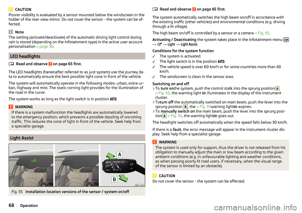
The high beam on/off is controlled by a sensor or a camera » Fig. 55.
Activating / Deactivating the system takes place in the Infotainment menu
→
→
Light
→
Light Assist
.
Conditions for the system function The system is activated.
The light switch is in the position .
The vehicle speed is over 60 km/h or for some countries more than 40
km/h.
The windscreen is clean in the sensor area.
Switching on and off
›
To turn on the system, push the control stalk into the sprung position
A
» Fig. 55 , the warning light
illuminates in the display of the instrument
cluster.
›
To turn off the automatically switched on main beam, push the lever into the
sprung position
B
, the » Fig. 55 warning light
expires.
›
To
manually switch on the main beam, push the lever into the sprung posi-
tion
A
» Fig. 55 , the warning light
goes out.
The headlight switches off automatically when the speed falls below 30 km/h.
If there is a fault, the error message will appear in the instrument cluster dis-
play. Seek help from a specialist garage.
WARNINGThe system is used only for support, thus the driver is not released from his
obligation to manually adjust the main or low beam according to the given
ambient conditions (e.g. in unfavourable lighting and weather conditions,
as when passing poorly lit road users, if necessary, when the visual range
of the sensor is limited by an obstacle).
CAUTION
Do not cover the sensor - the system can be affected.68Operation
Page 74 of 344
Option 3 - switching on/off (by pressing relevant switch) » Fig. 60
Reading lamp left
Reading lamp right
The rear lighting (variants 1 and 3) is controlled together with the automatic
operation of the lighting from the front seats. ▶ When the front interior lighting is switched on, the rear interior lighting also
turns on automatically.
▶ When the front interior lighting is switched off, the rear interior lighting can
be turned on/off as required.
Ambient lighting
Fig. 61
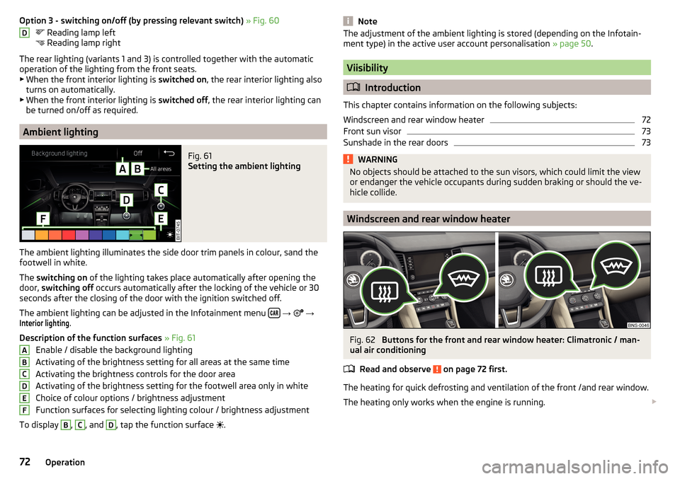
Setting the ambient lighting
The ambient lighting illuminates the side door trim panels in colour, sand the
footwell in white.
The switching on of the lighting takes place automatically after opening the
door, switching off occurs automatically after the locking of the vehicle or 30
seconds after the closing of the door with the ignition switched off.
The ambient lighting can be adjusted in the Infotainment menu
→
→
Interior lighting
.
Description of the function surfaces » Fig. 61
Enable / disable the background lighting
Activating of the brightness setting for all areas at the same time
Activating the brightness controls for the door area
Activating of the brightness setting for the footwell area only in white
Choice of colour options / brightness adjustment
Function surfaces for selecting lighting colour / brightness adjustment
To display
B
,
C
, and
D
, tap the function surface .
DABCDEFNoteThe adjustment of the ambient lighting is stored (depending on the Infotain-
ment type) in the active user account personalisation » page 50.
Viisibility
Introduction
This chapter contains information on the following subjects:
Windscreen and rear window heater
72
Front sun visor
73
Sunshade in the rear doors
73WARNINGNo objects should be attached to the sun visors, which could limit the view
or endanger the vehicle occupants during sudden braking or should the ve-
hicle collide.
Windscreen and rear window heater
Fig. 62
Buttons for the front and rear window heater: Climatronic / man-
ual air conditioning
Read and observe
on page 72 first.
The heating for quick defrosting and ventilation of the front /and rear window.
The heating only works when the engine is running.
72Operation