display SKODA KODIAQ 2016 1.G Owner's Manual
[x] Cancel search | Manufacturer: SKODA, Model Year: 2016, Model line: KODIAQ, Model: SKODA KODIAQ 2016 1.GPages: 344, PDF Size: 58.96 MB
Page 4 of 344
Table of Contents
Liability for defects and ŠKODA warranty for
new cars5
Printed Owner's Manual
7
Online Owner's Manual
8
Notes
9
Structure of the Owner´s Manual and further
information
10
Abbreviations
Safety
Passive Safety
12
General information
12
Correct and safe seated position
12
emergency call
14
Seat belts
15
Using seat belts
15
Inertia reel and belt tensioners
18
Airbag system
19
Description of the airbag system
19
Airbag deactivation
22
Transporting children safely
23
Child seat
23
Fastening systems
27
Operation
Cockpit
31
Overview
30
Instruments and warning lights
32
Instrument cluster
32
Warning lights
33Information system43Driver information system43
Operation of the information system
45
Driving data (Multifunction display)
46
MAXI DOT display
48
Service interval display
49
Personalization
50
Unlocking and opening
52
Unlocking and locking
52
Anti-theft alarm system
57
Manually operated tailgate
58
Electric boot lid
59
Window operation
61
Panoramic tilt / slide sunroof
63
Lights and visibility
65
Light
65
Interior lighting
71
Viisibility
72
Windscreen wipers and washers
73
Rear view mirror
75
Seats and head restraints
78
Front seats
78
Rear seats
80
Headrests
83
Seat heating and ventilation
85
Heated steering wheel
86
Practical features
87
Interior equipment
87
Electrical sockets
96
Ashtray and cigarette lighter
98
Tablet holder
99Transport of cargo100Luggage compartment100
Variable loading floor in the luggage
compartment (Estate)
106
Transportation on the roof rack
108
Heating and ventilation
109
Heating, manual air conditioning system,
Climatronic
109
Auxiliary heating (auxiliary heating and
ventilation)
114
Online services ŠKODA Connect
117
Introductory information
117
Care Connect-Services
118
infotainment online-Services
118
Infotainment
Introductory information
120
Important information
120
Infotainment Overview
121
Infotainment operation
124
Infotainment operation
124
Voice control
127
Updating the Infotainment software
129
Infotainment settings - Columbus, Amundsen,
Bolero
130
Infotainment system settings
130
Radio menu settings
133
Media menu settings
134
Image menu settings
134
Video DVD menu settings
134
Settings
134
SmartLink menu settings
136
Navigation menu settings
1362Table of Contents
Page 9 of 344
Printed Owner's Manual
In the printed Owner's Manual, the most important information relating to ve-
hicle operation is included. The Owner's Manual with further detailed informa- tion is available in the Online Version on ŠKODAweb pages » Fig. 1 on
page 8 .
These Owner´s Manual apply to all body variants of the vehicle and all related
model versions as well as all equipment levels .
This Owner's Manual describes all possible equipment variants without identi-
fying them as special equipment, model variants or market-dependent equip-
ment. Consequently, this vehicle does not contain all of the equipment com-
ponents described in this Owner's Manual.
The level of equipment in your vehicle refers to your purchase contract for the
vehicle. For any questions regarding the scope of equipment, please contact a
ŠKODA Partner.
The Pictures in this Owner's Manual are for illustrative purposes only. The il-
lustrations can differ in minor details from your vehicle; they are only intended
to provide general information.
ŠKODA AUTO pursues a policy of ongoing product and model development
with all vehicles. Changes in terms of supply scope are possible at any time
with regard to design, equipment and technology. The information listed in
this Owner's Manual corresponds to the information available at the time of
going to press.
Therefore legal claims cannot be made based on the technical data, illustra-
tions and information contained in this Owner's Manual.
We recommend that the web pages that are referred to in this Owner's Man-
ual are displayed using the classic view. If the web pages are displayed using
the mobile view, they may not contain all necessary information.7Printed Owner's Manual
Page 10 of 344
Online Owner's ManualFig. 1
Online manual on the ŠKODA
websites
The online Owner's Manual contains some detailed information, which is not
listed in the printed version of the manual.
To display the online Owner's Manual , proceed as follows.
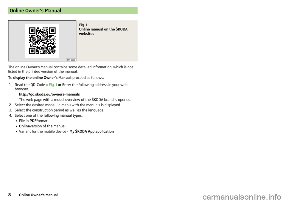
1.Read the QR-Code » Fig. 1 or Enter the following address in your web
browser. http://go.skoda.eu/owners-manuals The web page with a model overview of the ŠKODA brand is opened.2.Select the desired model - a menu with the manuals is displayed.3.Select the construction period as well as the language.4.Select one of the following manual types. File in PDFformat Online version of the manual Variant for the mobile device - My ŠKODA App application8Online Owner's Manual
Page 11 of 344
Notes
Terms used - Workshop - a workshop that carries out specialist service tasks
for ŠKODA vehicles. A specialist can be a ŠKODA Partner, a ŠKODA Serv- ice Partner, or an independent workshop.
- A workshop that has been contractually authorised
by ŠKODA AUTO or its distribution partner to perform service work on
ŠKODA vehicles and to sell ŠKODA Genuine Parts.
- A company that has been authorised by ŠKODA AUTO or its
distribution partner to sell new ŠKODA vehicles and, when applicable, to
service them using ŠKODA Genuine Parts and sell ŠKODA Genuine Parts.
Text notes - Short press (e.g. a button) within 1 s
- Long press (e.g. a button) for more than 1 s
Explanation of symbolsReference to the introductory module of a chapter with important infor-
mation and safety warningsSituations in which the vehicle must be stopped as soon as possible®Registered trademarkTelephone operation in the MAXI DOT displayText display in the segment display→Marker to the next operation stepWARNINGTexts with this symbol draw attention to threats of a serious accident, in-
jury or loss of life .
CAUTION
Texts with this symbol draw attention to the risk of vehicle damage or possible
inoperability of some systems.
Note
Texts with this symbol contain additional information.“Specialist”“ŠKODA Service Partner”“ŠKODA Partner”“Press”“Hold”9Notes
Page 12 of 344
Structure of the Owner´s Manual and further
information
Structure of the manual
The Owner's Manual is hierarchically divided into the following areas.
■ Paragraph (e.g. Operating instructions) - the title of the paragraph is always
indicated on the lower left-hand side ■ Main chapter (e.g. Checking and refilling) - the title of the main chapter is
always indicated on the lower right-hand side ■ Chapter (e.g. Engine oil)
■ Introductory information
- Module overview within the chapter, in-
troductory information about the chapter content and, where appropri-
ate, information relevant to the whole chapter
■ Module (e.g. Checking and refilling)
Information search
When searching for information in the Owner´s Manual, we recommend using
the Index at the end of the Owner's Manual.
Direction indications
All direction indications such as “left”, “right”, “front”, “rear” relate to the for- ward direction of travel of the vehicle.
Units
The volume, weight, speed and length data are given in metric units, unless
otherwise indicated.
Display
In this Owner's Manual, the MAXI DOT display is used as the display in the in-
strument cluster unless otherwise stated.
Emergency assistance
In the case of a breakdown, the required breakdown service contact informa- tion can be found in the following locations.
▶ Contact information from ŠKODA Partner (e.g. window sticker)
▶ Infotainment (Phone - breakdown service / information service menu)
▶ Mobile application ŠKODA
▶ ŠKODA websites10Structure of the Owner´s Manual and further information
Page 17 of 344
Manual establishment of connection›Press the button B » Fig. 4 for longer than 3 s (the established connectioncan be terminated by pressing the button again).
›
To confirm the connection setup displayed in the Infotainment screen / onthe display of the instrument cluster or wait a few seconds, the connection isset up automatically. The warning light
A
flashes green.
The Function of the system is displayed after switching on the ignition bylighting up of warning light
A
» Fig. 4.▶When the system is operational, the warning light will illuminate green.▶In the case of a system fault, the warning light illuminates red.
WARNING■The availability of a mobile network is indispensable for the system func-tion - no emergency call is possible if a mobile network is not available.■
In the case of a system fault there is a risk that the system will not acti-vate in the event of an accident. This must be checked immediately by aspecialized garage.
Note
Seat belts
Using seat belts
Introduction
This chapter contains information on the following subjects:
Correct routing of seat belt
16
Fastening and unfastening seat belts
17
Seat belts that are fastened correctly offer good protection in the event of anaccident. They reduce the risk of an injury and increase the chance of survivalin the event of a major accident.
The seat belts reduce the kinetic energy considerably. They also prevent un-controlled movements which, in turn, may well result in severe injuries.
When transporting children, observe the following information» page 23,Transporting children safely.
WARNING■Put the seat belt on before starting any journey! This also applies to otherpassengers - there is a danger of injury!■
Maximum seat belt protection is only achieved if you are correctly seated» page 12, Correct and safe seated position.
■
The seat backrests of the front seats must not be tilted too far to the rearotherwise the seatbelts can lose their effectiveness.
WARNINGInformation on dealing with the safety belts■The belt webbing must not be jammed in-between at any point or twis-ted, or chafe against any sharp edges.
■
Make sure you do not catch the seat belt in the door when closing it.
WARNINGInformation on the proper use of safety belts■Adjust the height of the belt in such a way that the shoulder part of thebelt is roughly positioned across the middle of your shoulder - on no ac-count across your neck.
15Seat belts■Along with the connection to the emergency call number, the system sendsthe predefined vehicle and occupant data time at the time of the accident (e.g.the vehicle identification number, the vehicle location, the number of unbeltedoccupants, the number of deployed airbags and other similar information) tothe emergency call centre.
■
If the vehicle is located in an area without an operational emergency call sys-tem infrastructure, then the vehicle data is not transmitted to the emergencycall centre.
Page 24 of 344
Airbag deactivation
Introduction
This chapter contains information on the following subjects:
Deactivating airbags
22
Deactivating the front passenger airbag
22
Deactivating airbags
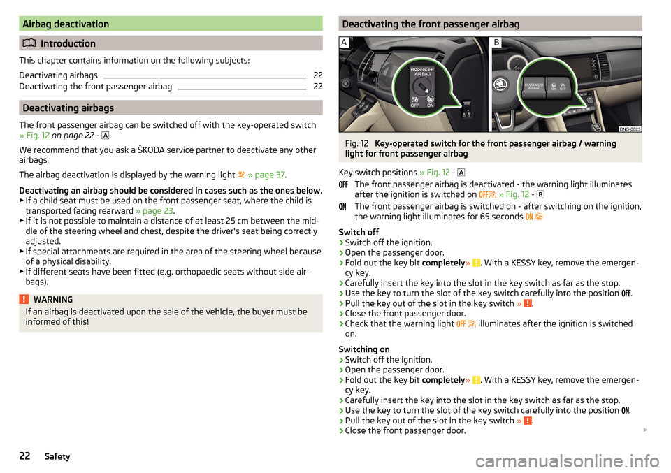
The front passenger airbag can be switched off with the key-operated switch
» Fig. 12 on page 22 -
.
We recommend that you ask a ŠKODA service partner to deactivate any other
airbags.
The airbag deactivation is displayed by the warning light
» page 37 .
Deactivating an airbag should be considered in cases such as the ones below. ▶ If a child seat must be used on the front passenger seat, where the child is
transported facing rearward » page 23.
▶ If it is not possible to maintain a distance of at least 25 cm between the mid-
dle of the steering wheel and chest, despite the driver's seat being correctly
adjusted.
▶ If special attachments are required in the area of the steering wheel because
of a physical disability.
▶ If different seats have been fitted (e.g. orthopaedic seats without side air-
bags).
WARNINGIf an airbag is deactivated upon the sale of the vehicle, the buyer must be
informed of this!Deactivating the front passenger airbagFig. 12
Key-operated switch for the front passenger airbag / warning
light for front passenger airbag
Key switch positions » Fig. 12 -
The front passenger airbag is deactivated - the warning light illuminates
after the ignition is switched on
» Fig. 12 -
The front passenger airbag is switched on - after switching on the ignition,
the warning light illuminates for 65 seconds
Switch off
›
Switch off the ignition.
›
Open the passenger door.
›
Fold out the key bit completely» . With a KESSY key, remove the emergen-
cy key.
›
Carefully insert the key into the slot in the key switch as far as the stop.
›
Use the key to turn the slot of the key switch carefully into the position .
›
Pull the key out of the slot in the key switch
» .
›
Close the front passenger door.
›
Check that the warning light
illuminates after the ignition is switched
on.
Switching on
›
Switch off the ignition.
›
Open the passenger door.
›
Fold out the key bit completely» . With a KESSY key, remove the emergen-
cy key.
›
Carefully insert the key into the slot in the key switch as far as the stop.
›
Use the key to turn the slot of the key switch carefully into the position .
›
Pull the key out of the slot in the key switch
» .
›
Close the front passenger door.
22Safety
Page 34 of 344
Instruments and warning lights
Instrument cluster
Introduction
Fig. 20
Instrument cluster
This chapter contains information on the following subjects:
Engine revolutions counter
32
Coolant temperature gauge
32
Fuel gauge
33
Display in the rear centre console
33
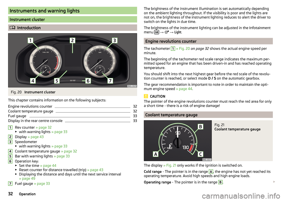
Rev counter » page 32
▶ with warning lights » page 33
Display » page 43
Speedometer
▶ with warning lights » page 33
Coolant temperature gauge » page 32
Bar with warning lights » page 33
Operation key:
▶ Set the time » page 44
▶ Reset counter for distance travelled (trip) » page 43
▶ Displaying the distance and days until the next service interval
» page 49
Fuel gauge » page 33
1234567The brightness of the instrument illumination is set automatically depending
on the ambient lighting throughout. If the visibility is poor and the lights are
not on, the brightness of the instrument lighting reduces to alert the driver to
switch on the lights in due time.
The brightness of the instrument lighting can be adjusted in the Infotainment
menu
→
→
Light
.
Engine revolutions counter
The tachometer
1
» Fig. 20 on page 32 shows the actual engine speed per
minute.
The beginning of the tachometer red scale range indicates the maximum per-
mitted speed for an engine that has been driven-in and has reached operating
temperature.
You should shift into the next highest gear before the red scale of the revolu-
tion counter is reached, or select mode D / S on the automatic gearbox.
The gear recommendation is important to note in order to maintain the opti-
mum engine speed » page 44.
CAUTION
The pointer of the engine revolutions counter must reach the red area for only
a short time - there is a risk of engine damage!
Coolant temperature gauge
Fig. 21
Coolant temperature gauge
The display » Fig. 21 only works if the ignition is switched on.
Cold range - The pointer is in the range
A
, the engine has not yet reached its
operating temperature. Avoid high speeds and high engine loads.
Operating range - The pointer is in the range
B
.
32Operation
Page 35 of 344
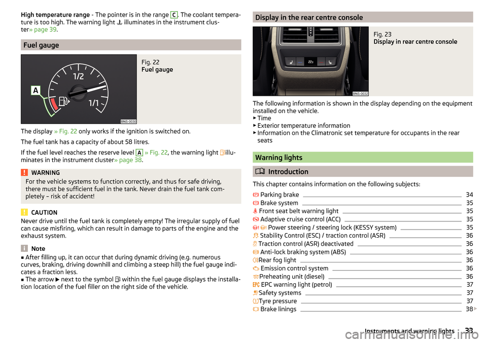
High temperature range - The pointer is in the range C. The coolant tempera-
ture is too high. The warning light illuminates in the instrument clus-
ter » page 39 .
Fuel gauge
Fig. 22
Fuel gauge
The display » Fig. 22 only works if the ignition is switched on.
The fuel tank has a capacity of about 58 litres.
If the fuel level reaches the reserve level
A
» Fig. 22 , the warning light
illu-
minates in the instrument cluster » page 38.
WARNINGFor the vehicle systems to function correctly, and thus for safe driving,
there must be sufficient fuel in the tank. Never drain the fuel tank com-
pletely – risk of accident!
CAUTION
Never drive until the fuel tank is completely empty! The irregular supply of fuel
can cause misfiring, which can result in damage to parts of the engine and the
exhaust system.
Note
■ After filling up, it can occur that during dynamic driving (e.g. numerous
curves, braking, driving downhill and climbing a steep hill) the fuel gauge indi-
cates a fraction less.■
The arrow
next to the symbol
within the fuel gauge displays the installa-
tion location of the fuel filler on the right side of the vehicle.
Display in the rear centre consoleFig. 23
Display in rear centre console
The following information is shown in the display depending on the equipment
installed on the vehicle.
▶ Time
▶ Exterior temperature information
▶ Information on the Climatronic set temperature for occupants in the rear
seats
Warning lights
Introduction
This chapter contains information on the following subjects:
Parking brake
34
Brake system
35
Front seat belt warning light
35
Adaptive cruise control (ACC)
35
Power steering / steering lock (KESSY system)
35
Stability Control (ESC) / traction control (ASR)
36
Traction control (ASR) deactivated
36
Anti-lock braking system (ABS)
36
Rear fog light
36
Emission control system
36
Preheating unit (diesel)
36
EPC warning light (petrol)
37
Safety systems
37
Tyre pressure
37
Brake linings
38
33Instruments and warning lights
Page 36 of 344
Fuel reserve38 Lane Departure Warning (Lane Assist)38
Turn signal system
38
Trailer turn signal lights
38
Fog lights
38
Speed regulating system / speed limiter
38
Brake pedal (automatic gearbox)
38
Auto Hold function
39
Main beam
39
Automatic gearbox
39
Rear seat belt warning light
39
Generator
39
Coolant
39
Engine oil pressure
40
Engine oil level
40
AdBlue ®
(diesel engine)
40
Lamp failure
41
Diesel particle filter (diesel)
41
Windscreen washer fluid level
41
High-beam assistant
41
START-STOPsystem
41
Display of a low temperature
42
Water in the fuel filter (diesel engine)
42
Adaptive Cruise Control (ACC)
42
Front Assist
42
Front assist
42
Economy mode
42
OFF ROAD mode
42
Adaptive Chassis Control (DCC)
42
Service
43
The warning lights in the instrument cluster indicate certain functions or
faults.
Some warning lights can be accompanied by acoustic signals and messages in
the display of the instrument cluster.
After switching on the ignition, some warning lights light up briefly as a func-
tion test. If the tested systems are OK, the corresponding warning lights go
out a few seconds after switching on the ignition or after starting the engine.
The warning lights are located at the following positions in the instrument
cluster » Fig. 20 on page 32 .
▶ Engine revolutions counter 1
▶Display
2
▶Speedometer
3
▶Bar with warning lights
5
Warning lights in the display
Depending on the importance the warning light
(danger) or
(warning) illu-
minate along with some of the warning lights in the list with the warning
lights.
Depending on vehicle equipment some warning lights can be displayed in col-
our on the display. For example. the coolant warning lamp may be represented
as follows.
▶ - Segment display / monochromatic (“black and white”) MAXI DOT display
▶ - Coloured MAXI DOT display
WARNING■
Ignoring illuminated warning lights and related messages or instructions
in the display of the instrument cluster may lead to serious personal injury
or damage to the vehicle.■
If you have to stop for technical reasons, then park the vehicle at a safe
distance from the traffic, switch off the engine and switch on the hazard
warning lights » page 70. Place the warning triangle at the prescribed dis-
tance.
■
The engine compartment of your car is a hazardous area. While working in
the engine compartment, be sure to observe the following warnings
» page 278 .
Parking brake
Read and observe
on page 34 first.
illuminates - the parking brake is switched on.
Parking brake error
Illumi-
nates
Error: electronic parking brakePARKING BRAKE FAILURE
▶ Seek help from a specialist garage.
34Operation