ESP SKODA OCTAVIA 2005 1.G / (1U) Owner's Manual
[x] Cancel search | Manufacturer: SKODA, Model Year: 2005, Model line: OCTAVIA, Model: SKODA OCTAVIA 2005 1.G / (1U)Pages: 315, PDF Size: 11.8 MB
Page 7 of 315
Contents
6
Important safety information regarding the use
of seat belts . . . . . . . . . . . . . . . . . . . . . . . . . .
How are seat belts correctly fastened? . . . . .
Belt tensioners . . . . . . . . . . . . . . . . . . . . . . . .
Airbag system. . . . . . . . . . . . . . . . . . . . . . . . .
Description of the airbag system . . . . . . . . . .
Front airbags . . . . . . . . . . . . . . . . . . . . . . . . .
Side airbags* . . . . . . . . . . . . . . . . . . . . . . . . .
Head airbags* . . . . . . . . . . . . . . . . . . . . . . . .
Deactivating an airbag . . . . . . . . . . . . . . . . . .
Transporting children safely. . . . . . . . . . . . .
What you should know about transporting
children! . . . . . . . . . . . . . . . . . . . . . . . . . . . . .
Child seat . . . . . . . . . . . . . . . . . . . . . . . . . . . .
Attaching child seat using the “ISOFIX” system
Driving Tips . . . . . . . . . . . . . . . . . . . . . .
Intelligent Technology . . . . . . . . . . . . . . . . . .
Electronic stability programme (ESP)* . . . . . .
Brakes . . . . . . . . . . . . . . . . . . . . . . . . . . . . . .
Brake booster . . . . . . . . . . . . . . . . . . . . . . . .
Antilock brake system (ABS) . . . . . . . . . . . . .
Brake Assist* . . . . . . . . . . . . . . . . . . . . . . . . .
Uphill-Start off-Assist* . . . . . . . . . . . . . . . . . .
Electromechanical power steering . . . . . . . . .
Tyre inflation pressure-control system* . . . . .
Driving and the Environment. . . . . . . . . . . .
The first 1 500 kilometres and then afterwards
Catalytic converter . . . . . . . . . . . . . . . . . . . . .
Driving in an economical and environmentally
conscious manner . . . . . . . . . . . . . . . . . . . . .
Environmental compatibility . . . . . . . . . . . . . .
Motoring abroad . . . . . . . . . . . . . . . . . . . . . . .
Avoiding damage to your vehicle . . . . . . . . . .
Towing a trailer. . . . . . . . . . . . . . . . . . . . . . . .
Towing a trailer . . . . . . . . . . . . . . . . . . . . . . .
Detachable ball head* . . . . . . . . . . . . . . . . . .
General Maintenance. . . . . . . . . .
Taking care of your vehicle and cleaning the
vehicle . . . . . . . . . . . . . . . . . . . . . . . . . . . . . . .
General . . . . . . . . . . . . . . . . . . . . . . . . . . . . .
Care of the exterior of vehicle . . . . . . . . . . . .
Care of the interior of vehicle . . . . . . . . . . . . .
Fuel. . . . . . . . . . . . . . . . . . . . . . . . . . . . . . . . . .
Petrol . . . . . . . . . . . . . . . . . . . . . . . . . . . . . . .
Diesel . . . . . . . . . . . . . . . . . . . . . . . . . . . . . .
Refuelling . . . . . . . . . . . . . . . . . . . . . . . . . . .
Inspecting and Replenishing. . . . . . . . . . . .
Engine compartment . . . . . . . . . . . . . . . . . . .
Engine oil . . . . . . . . . . . . . . . . . . . . . . . . . . . .
Cooling system . . . . . . . . . . . . . . . . . . . . . . .
Brake fluid . . . . . . . . . . . . . . . . . . . . . . . . . . .
The battery . . . . . . . . . . . . . . . . . . . . . . . . . .
Windscreen Wiper and Washer System . . . .
Wheels and Tyres . . . . . . . . . . . . . . . . . . . . .
Wheels . . . . . . . . . . . . . . . . . . . . . . . . . . . . .
Accessories, changes and replacement of
parts . . . . . . . . . . . . . . . . . . . . . . . . . . . . . . . . .
Accessories and replacement parts . . . . . . .
Technical changes . . . . . . . . . . . . . . . . . . . . .
Breakdown assistance . . . . . . . .
Breakdown assistance . . . . . . . . . . . . . . . . .
First-aid box* and warning triangle* (Octavia)
First-aid box* and warning triangle* (Estate
car) . . . . . . . . . . . . . . . . . . . . . . . . . . . . . . . . Fire extinguisher* . . . . . . . . . . . . . . . . . . . . .
Vehicle tool kit . . . . . . . . . . . . . . . . . . . . . . . .
Tyre repair kit* . . . . . . . . . . . . . . . . . . . . . . . .
Spare wheel . . . . . . . . . . . . . . . . . . . . . . . . .
Changing a wheel . . . . . . . . . . . . . . . . . . . . .
Jump-starting . . . . . . . . . . . . . . . . . . . . . . . .
Tow-starting and towing vehicle . . . . . . . . . .
Fuses and light bulbs . . . . . . . . . . . . . . . . . .
Electric fuses . . . . . . . . . . . . . . . . . . . . . . . . .
Bulbs . . . . . . . . . . . . . . . . . . . . . . . . . . . . . . .
Te c h n i c a l D a ta . . . . . . . . . . . . . . . . . .
General . . . . . . . . . . . . . . . . . . . . . . . . . . . . . .
Identification data . . . . . . . . . . . . . . . . . . . . .
Index . . . . . . . . . . . . . . . . . . . . . . . . . . . . . .
185
186
188
190
190
192
195
197
199
202
202
206
210
213
213
213
216
217
218
218
219
219
220
221
221
222
223
227
228
228 229
229
231
233
233
233
233
239
242
242
242
245
247
247
250
253
256
258
262
263
263
270
270
270
273
273
273
273274
274
275
275
276
281
283
288
288
294
303
303
303
305
s24s.book Page 6 Thursday, November 24, 2005 12:27 PM
Page 9 of 315
Layout of this Owner's Manual (explanations)
8
Layout of this Owner' s Manual (explanations)
The Owner's Manual has been systematically designed, in order to make
it easy for you to find and absorb the information you require.
Chapters, table of contents and subject index
The text of the manual are divided into relatively short sections which are
combined into easy-to-read chapters. The chapter you are reading at any
particular moment is highlighted at the bottom right of the page.
The Table of contents is arranged according to the chapters and the
detailed Subject index at the end of the Owner's Manual helps you to
rapidly find the information you are looking for.
Sections
The majority of Sections apply to all models.
Since there is a wide range of different equipment and options available it
is clearly unavoidable, despite dividing the contents into sections, that
mention may be made of equipment which is not fitted to your vehicle.
Equipment which is marked * is only standard on certain vehicle model
versions or only suppliable as optional equipment for certain models.
Brief information and instructions
Each section has a Heading.
This is followed by Brief information (in large italic lettering), which tells
you the subject which is dealt with in this section.
Most of the illustrations are accompanied by an Instruction (in relatively
large letters) which explains to you in a straightforward way the action you
have to take. Work steps which have to be carried out are illustrated with
a hyphen.
Notes
All four kinds of notes, which are used in the text, are always stated at the
end of the respective section.
WARNING
The most important notes are marked with the heading Warning.
These Warning notes draw your attention to a serious risk of acci-
dent or injury. While reading the text you will frequently encounter
a double arrow followed by a small warning symbol. This symbol is
intended to draw your attention to a Warning note at the end of the
section to which you must pay careful attention.
Caution
A Caution note draws your attention to the possibility of damage to your
vehicle (e.g. damage to gearbox), or points out general risks of an acci-
dent .
For the sake of the environment
An Environmental note draws your attention to environmental protection
aspects. This is where you will, for example, find tips aimed at reducing
your fuel consumption.
Note
A normal Note draws your attention in a general way to important informa-
tion.
Direction indications
All direction indications such as “left”, “right”, “front”, “rear” relate to the
direction of travel of the vehicle.
s24s.book Page 8 Thursday, November 24, 2005 12:27 PM
Page 12 of 315
Cockpit11
Using the systemSafetyDriving TipsGeneral MaintenanceBreakdown assistanceTechnical Data
Cockpit
An overview
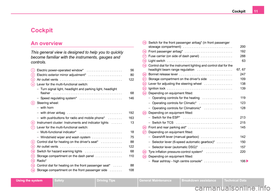
This general view is designed to help you to quickly
become familiar with the instruments, gauges and
controls.
Electric power-operated window* . . . . . . . . . . . . . . . . . . . .
Electric exterior mirror adjustment* . . . . . . . . . . . . . . . . . . .
Air outlet vents . . . . . . . . . . . . . . . . . . . . . . . . . . . . . . . . . . .
Lever for the multi-functional switch:
−Turn signal light, headlight and parking light, headlight
flasher . . . . . . . . . . . . . . . . . . . . . . . . . . . . . . . . . . . . . . .
− Speed regulating system* . . . . . . . . . . . . . . . . . . . . . . . .
Steering wheel:
− with horn
− with driver airbag . . . . . . . . . . . . . . . . . . . . . . . . . . . . . . .
− with pushbuttons for radio and mobile phone* . . . . . . . .
Instrument cluster: Instruments and indicator lights . . . . . .
Lever for the multi-functional switch:
− Multi-functional indicator* . . . . . . . . . . . . . . . . . . . . . . . .
− Windshield wiper and wash system . . . . . . . . . . . . . . . . .
Control dial for heating on the driver's seat* . . . . . . . . . . . .
Air outlet vents . . . . . . . . . . . . . . . . . . . . . . . . . . . . . . . . . . .
Switch for hazard warning lights . . . . . . . . . . . . . . . . . . . . .
Storage compartment on the dash panel . . . . . . . . . . . . . . .
Radio*
Control dial for heating on the front passenger seat* . . . . .
Storage compartment on the front passenger side . . . . . . . Switch for the front passenger airbag* (in front passenger
stowage compartment) . . . . . . . . . . . . . . . . . . . . . . . . . . . .
Front passenger airbag* . . . . . . . . . . . . . . . . . . . . . . . . . . .
Fuse carrier (on side of dash panel) . . . . . . . . . . . . . . . . . .
Light switch . . . . . . . . . . . . . . . . . . . . . . . . . . . . . . . . . . . . .
Control dial for the instrument lighting and control dial for the
headlight beam range regulation . . . . . . . . . . . . . . . . . . . .
Bonnet release lever . . . . . . . . . . . . . . . . . . . . . . . . . . . . . .
Storage compartment on the driver's side . . . . . . . . . . . . .
Lever for adjusting the steering wheel . . . . . . . . . . . . . . . .
Ignition lock . . . . . . . . . . . . . . . . . . . . . . . . . . . . . . . . . . . . .
Depending on equipment fitted:
−
Operating controls for the heating . . . . . . . . . . . . . . . . .
− Operating controls for Climatic* . . . . . . . . . . . . . . . . . . .
− Operating controls for Climatronic* . . . . . . . . . . . . . . . .
Depending on equipment fitted:
− Switch for the ESP* . . . . . . . . . . . . . . . . . . . . . . . . . . . .
− Switch for TCS . . . . . . . . . . . . . . . . . . . . . . . . . . . . . . . .
Front and rear parking aid* . . . . . . . . . . . . . . . . . . . . . . . . .
Depending on equipment fitted:
− Gearshift lever (manual gearbox) . . . . . . . . . . . . . . . . . .
− Selector lever (6-speed automatic gearbox)* . . . . . . . . .
− Selector lever (automatic DSG)* . . . . . . . . . . . . . . . . . .
Tyre inflation pressure-control system* . . . . . . . . . . . . . . .
Depending on equipment fitted:
− Rear ashtray - high centre console* . . . . . . . . . . . . . . . . A156
A280
A3122
A4
68
146
A5
192
163
A613
A7
18
75
A888
A9122
A1068
A1111 0
A12
A1388
A14108
A15200
A16192
A17288
A1863
A1967, 67
A20247
A21109
A22138
A23139
A24
11 9
123
128
A25
213
215
A26145
A27
142
150
157
A28220
A29
106
s24s.book Page 11 Thursday, November 24, 2005 12:27 PM
Page 28 of 315
Instruments and Indicator/Warning Lights27
Using the systemSafetyDriving TipsGeneral MaintenanceBreakdown assistanceTechnical Data
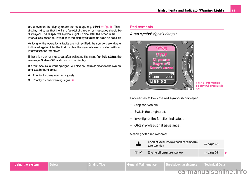
are shown on the display under the message e.g.
01/03 ⇒ fig. 15 . This
display indicates that the first of a total of three error messages should be
displayed. The respective symbols light up one after the other in an
interval of 5 seconds. Investigate the displayed faults as soon as possible.
As long as the operational faults are not rectified, the symbols are always
indicated again. After the first display, the symbols are indicated without
information for the driver.
If there is no error message, after selecting the menu Vehicle status the
message Status OK is shown on the display.
If a fault occurs, a warning signal will also sound in addition to the symbol
and text in the display:
•Priority 1 - three warning signals
•Priority 2 - one warning signal
Red symbols
A red symbol signals danger.
Proceed as follows if a red symbol is displayed:
– Stop the vehicle.
– Switch the engine off.
– Investigate the function indicated.
– Obtain professional assistance.
Meaning of the red symbols:
Coolant level too low/coolant tempera-
ture too high⇒ page 35
Engine oil pressure too low⇒page 37
Fig. 16 Information
display: Oil pressure is
low
s24s.book Page 27 Thursday, November 24, 2005 12:27 PM
Page 30 of 315
Instruments and Indicator/Warning Lights29
Using the systemSafetyDriving TipsGeneral MaintenanceBreakdown assistanceTechnical Data
You can change certain settings by means of the information display. The
current setting is shown on the information display in the respective menu
at the top below the line
⇒page 28, fig. 18 .
You can select the following information (depending on the equipment
installed on the vehicle):
•Time
•Winter tyres
•Language
•Units
•Lights & Vision
•Aux. Heating (auxiliary heating)
•Back
After selecting the menu Back you will reach one level higher in the menu.
Setting clock
Here you can set the time, the time format (12 or 24 hour indicator) and
the time change summer/winter time.
Setting for winter tyre speed
Here you can set at which speed a warning signal should sound. These
functions are used for e.g on winter tyres with the permissible maximum
speed less than the maximum speed of the vehicle ⇒page 266.
When exceeding the speed, the following is displayed on the information
display*: Speed warning
Language setting
Here you can set in which language the warning and information texts
should be displayed. After selecting the language, e.g. English, the
following is displayed on the information display: Language: english set Setting units
Here you can set the units for temperature, consumption and distance
driven.
Setting lights
Here you can switch on or off the function convenience turn signal
⇒
page 68. Furthermore you can set how long the light should stay on for
the function Coming/Leaving Home ⇒page 66.
After selecting the menu Factory setting the factory setting is established
again.
s24s.book Page 29 Thursday, November 24, 2005 12:27 PM
Page 32 of 315
Instruments and Indicator/Warning Lights31
Using the systemSafetyDriving TipsGeneral MaintenanceBreakdown assistanceTechnical Data
WARNING
•If you do not pay attention to the warning lights coming on and
the corresponding descriptions and warning notes, this may result
in severe body injuries or major vehicle damage.
•The engine compartment of your car is a hazardous area. There
is a risk of injuries, scalding, accidents and fire when working in
the engine compartment, e.g. inspecting and replenishing oil and
other fluids. It is also essential to observe all warnings ⇒page 248.
Note
•Arrangement of the indicator lights depends on the model and model
version. The symbols shown in the following functional description are to
be found as indicator lights in the instrument cluster.
•Operational faults are shown in the instrument cluster as red symbols
(priority 1 - danger) or yellow symbols (priority 2 - warning).
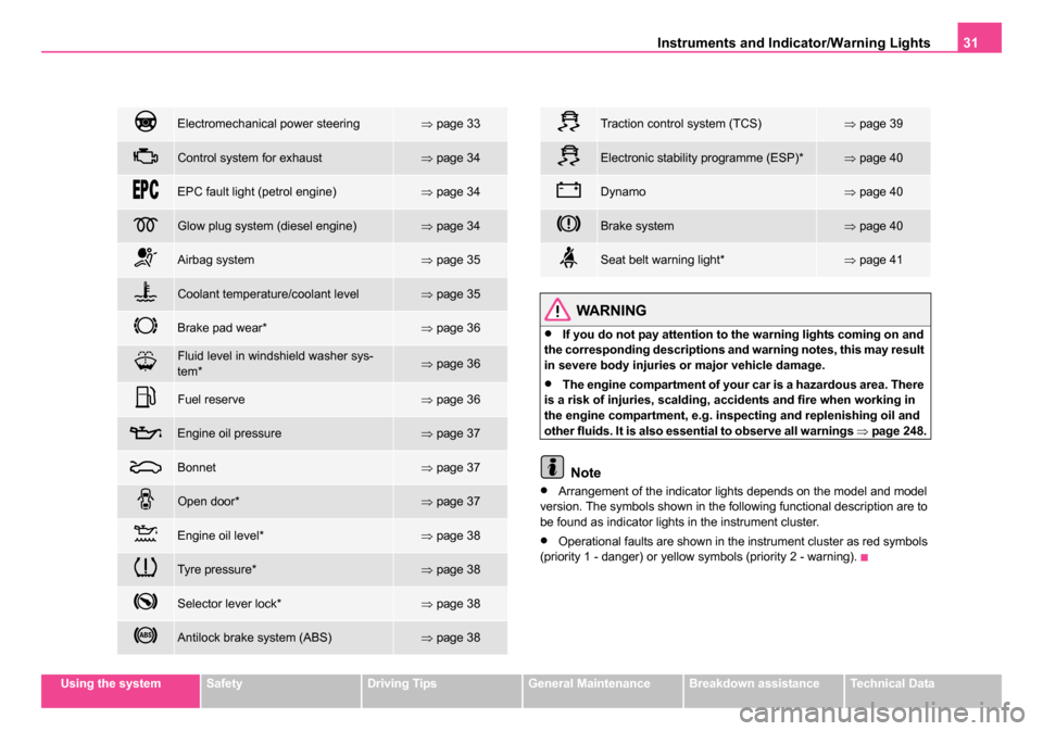
Electromechanical power steering⇒ page 33
Control system for exhaust⇒page 34
EPC fault light (petrol engine)⇒page 34
Glow plug system (diesel engine)⇒page 34
Airbag system⇒page 35
Coolant temperature/coolant level⇒page 35
Brake pad wear*⇒page 36
Fluid level in windshield washer sys-
tem*⇒page 36
Fuel reserve⇒page 36
Engine oil pressure⇒page 37
Bonnet⇒page 37
Open door*⇒page 37
Engine oil level*⇒page 38
Tyre pressure*⇒page 38
Selector lever lock*⇒page 38
Antilock brake system (ABS)⇒page 38
Traction control system (TCS)⇒page 39
Electronic stability programme (ESP)*⇒page 40
Dynamo⇒page 40
Brake system⇒page 40
Seat belt warning light*⇒page 41
s24s.book Page 31 Thursday, November 24, 2005 12:27 PM
Page 34 of 315
Instruments and Indicator/Warning Lights33
Using the systemSafetyDriving TipsGeneral MaintenanceBreakdown assistanceTechnical Data
Diesel particle filter (diesel engine)
In the diesel particle filter the resulting soot particles are
collected and burnt during the combustion of diesel fuel.
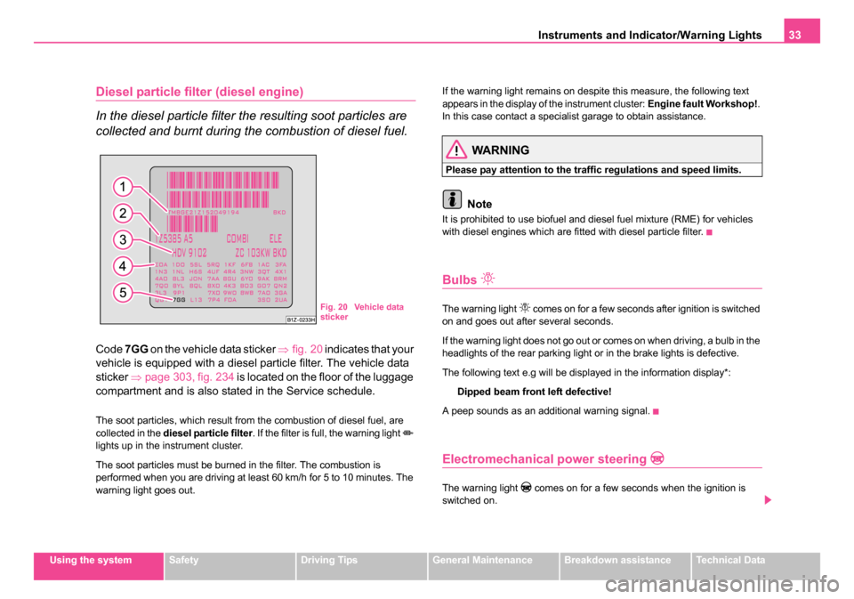
Code 7GG on the vehicle data sticker ⇒fig. 20 indicates that your
vehicle is equipped with a diesel particle filter. The vehicle data
sticker ⇒page 303, fig. 234 is located on the floor of the luggage
compartment and is also stated in the Service schedule.
The soot particles, which result from the combustion of diesel fuel, are
collected in the diesel particle filter . If the filter is full, the warning light
lights up in the instrument cluster.
The soot particles must be burned in the filter. The combustion is
performed when you are driving at least 60 km/h for 5 to 10 minutes. The
warning light goes out. If the warning light remains on despite this measure, the following text
appears in the display of the instrument cluster:
Engine fault Workshop!.
In this case contact a specialist garage to obtain assistance.
WARNING
Please pay attention to the traffic regulations and speed limits.
Note
It is prohibited to use biofuel and diesel fuel mixture (RME) for vehicles
with diesel engines which are fitted with diesel particle filter.
Bulbs
The warning light comes on for a few seconds after ignition is switched
on and goes out after several seconds.
If the warning light does not go out or comes on when driving, a bulb in the
headlights of the rear parking light or in the brake lights is defective.
The following text e.g will be displayed in the information display*:
Dipped beam front left defective!
A peep sounds as an additional warning signal.
Electromechanical power steering
The warning light comes on for a few seconds when the ignition is
switched on.
Fig. 20 Vehicle data
sticker
s24s.book Page 33 Thursday, November 24, 2005 12:27 PM
Page 41 of 315
Instruments and Indicator/Warning Lights
40
Note
If the battery has been disconnected and reconnected, the warning light comes on after switching on the ignition. The warning light must go out
after driving a short distance.
Electronic Stability Programme (ESP)*
The warning light comes on for a few seconds when the ignition is
switched on.
Components of the ESP system also include the Traction Control System
(TCS), Electronic Differential Lock (EDL), and the Antilock Brake System
(ABS).
The warning light comes on when driving when a control cycle is acti-
vated.
The warning lig ht will come on an d remains on if the ESP is switched off
or if there is a fault in the system.
The fact that the ESP system operates together with the ABS means that
the ESP warning light will also come on if the ABS system is not operating
properly.
If the warning light
comes on immediately after starting the engine, the
ESP system can be switched off for technical reasons. In this case, the
ESP system can be switched on again by switching the ignition on and off.
If the warning light goes out, the ESP system is fully functional again.
Further information on the ESP ⇒page 213, “Electronic stability
programme (ESP)*”.
Electronic Differential Lock (EDL)*
The EDL is a part of the ESP. A fault in the EDL is indicated by the ESP
warning light in the instrument cluster. Have the vehicle inspected without delay by a Škoda dealer. Further information on the EDL
⇒page 214,
“Electronic Differential Lock (EDL)*”.
Note
If the battery has been disconnected and reconnected, the warning light comes on after switching on the ignition. The warning light must go out
after driving a short distance.
Dynamo
The warning light comes on after the ignition has been switched on. It
should go out after the engine has started.
If the warning light does not go out after the engine has started, or comes
on when driving, drive to the nearest specialist garage. The vehicle battery
will be discharged in this case so switch off all non-essential electrical
components.
Caution
If the warning light comes on when driving and in addition the warning
light (cooling system fault) also comes on in display, you must then
stop the car immediately and switch the engine off - risk of engine
damage!
Brake system
The warning light flashes or comes on if the brake fluid level is too low,
if there is a fault in the ABS or if the handbrake is applied.
s24s.book Page 40 Thursday, November 24, 2005 12:27 PM
Page 57 of 315
Unlocking and locking
56
– Open the driver door.
– Press the button
at the centre colum on the driver side
⇒ page 55, fig. 35 , the symbol
lights up in the button.
– Lock the vehicle within 30 seconds.
The interior monitor is switched on again automatically the next time the
car is locked.
Power windows*
Buttons on the driver's door
The power windows operate only when ignition is switched on. Opening a window
– A window is opened by pressing lightly on the respective
button in the door. The process stops when one releases the
button.
– Additionally you can open the window automatically (fully opened) by pressing the button up to the stop. Renewed
pressing of the button causes the window to stop immediately.
Closing a window
– A window is closed through pulling lightly on the respective button in the door. The closing process stops when one
releases the button.
– Additionally you can close the window automatically (fully closed) by pulling the button up to the stop. Renewed pulling
of the button causes the window to stop immediately.
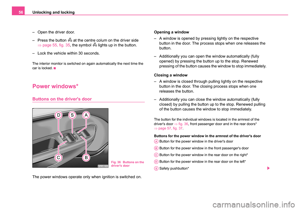
The button for the individual windows is located in the armrest of the
driver's door ⇒fig. 36 , front passenger door and in the rear doors*
⇒ page 57, fig. 37 .
Buttons for the power window in the armrest of the driver's door Button for the power window in the driver's door
Button for the power window in the front passenger's door
Button for the power window in the rear door on the right*
Button for the power window in the rear door on the left*
Safety pushbutton*
Fig. 36 Buttons on the
driver's door
AA
AB
AC
AD
AS
s24s.book Page 56 Thursday, November 24, 2005 12:27 PM
Page 66 of 315
Lights and Visibility65
Using the systemSafetyDriving TipsGeneral MaintenanceBreakdown assistanceTechnical Data
WARNING
The automatic driving lamp control only operates as a support. The
driver is not released from his responsibility to inspect the light
and if necessary to switch on the light depending on the light
conditions. The light sensor cannot detect for example rain or
snow. Always switch on the low beam
under these conditions
as well as when driving in the dark!
Note
•Do not affix any stickers in front of the light sensor, so that you do not
impair its function or put it out of operation.
•The same principles as for using the automatic driving lamp control
also apply to the light which is switched on manually ⇒page 63.
Fog lights*
Switching on the fog lights
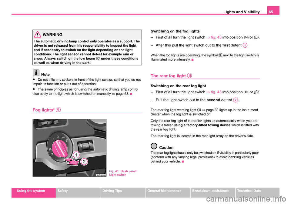
– First of all turn the light switch ⇒fig. 43 into position
or .
– After this pull the light switch out to the first detent .
When the fog lights are operating, the symbol next to the light switch is
illuminated more intensely.
The rear fog light
Switching on the rear fog light
– First of all turn the light switch ⇒fig. 43 into position
or .
– Pull the light switch out to the second detent .
The rear fog light warning light ⇒ page 30 lights up in the instrument
cluster when the fog light is switched off.
Only the rear fog light of the trailer lights up automatically when you are
towing a trailer using a factory-fitted towing device which is fitted with
the rear fog light.
The rear fog light is located in the rear light array on the driver's side.
Caution
The rear fog light should only be switched on if visibility is particularly poor
(conform with any varying legal provisions) to avoid dazzling vehicles
behind your vehicle.
Fig. 43 Dash panel:
Light switch
A1
A2
s24s.book Page 65 Thursday, November 24, 2005 12:27 PM