auxiliary battery SKODA OCTAVIA 2006 Owner´s Manual
[x] Cancel search | Manufacturer: SKODA, Model Year: 2006, Model line: OCTAVIA, Model: SKODA OCTAVIA 2006Pages: 218, PDF Size: 5.48 MB
Page 89 of 218

Switching recirculated air mode on
›
Repeatedly press the button
5
» Fig. 90
on page 85 until the warning
light on the left side of the button is illuminated.
Switch on automatic air distribution control
› Repeatedly press the button
5
» Fig. 90
on page 85 until the warning
light on the right side of the button is illuminated.
Switch off automatic air distribution control temporarily
› If the air quality sensor does not automatically switch on the air distribution
control in the event of an unpleasant odour, you can switch it on yourself by
pressing the button 5
» Fig. 90
on page 85. The warning light lights up in
the button on the left side.
Switching recirculated air mode off
› Press the button
AUTO 8
» Fig. 90
on page
85 or repeatedly press the button
5
» Fig. 90 on page 85
until the warning lights in the button go out.WARNING
Do not leave recirculated air mode on over a longer period of time, as “stale”
air can cause fatigue of the driver and passengers, reduce attention levels and
also cause the windows to mist up. The risk of having an accident increases.
Switch off recirculated air mode as soon as the windows start to mist up. Note
■ If the windscreen mists up, press the button 1
» Fig. 90 on page 85
. Press
the button AUTO 8
» Fig. 90
on page 85 when the windshield is demisted.
■ The automatic air distribution control operates only if the outside temperature
is higher than approx. 2 °C. ÐControlling blower
The Climatronic system controls the blower stages automatically in line with the
interior temperature. However, the blower stages can be manually adapted to
suit your particular needs.
› Repeatedly press the button
10
» Fig. 90
on page 85 on the left side (reduce
blower speed) or on the right side (increase blower speed).
If the blower is switched off, the Climatronic system is switched off.
The set blower speed is displayed above the button 10
» Fig. 90 on page 85
when the respective number of warning lights come on. WARNING
■ “
Stale air” may result in fatigue in the driver and occupants, reduce attention
levels and also cause the windows to mist up. The risk of having an accident
increases.
■ Do not switch off the Climatronic system for longer than necessary.
■ Switch on the Climatronic system as soon as the windows mist up. Ð Defrosting windscreen
Switching on › Press the button
1
» Fig. 90
on page 85.
Switching off
› Once again press the button
1
» Fig. 90 on page 85
or the button AUTO .
The temperature control is controlled automatically. More air flows out of the air
outlet vents 1 » Fig. 86 on page 80
. Ð Auxiliary heating (auxiliary heating and ventilation)
ä
Introduction
This chapter contains information on the following subjects:
Direct switching on/off 88
System settings 89
Radio remote control 89
Changing the battery of the radio remote control 90
Auxiliary heating (parking heating)
The auxiliary heater (parking heater) functions in connection with the air-condi-
tioning system or Climatronic.
It can be used when stationary, when the engine is switched off to preheat the
vehicle and while driving (e.g. during the heating phase of the engine).
The engine is also preheated, if the auxiliary heating is switched on when the ve-
hicle is stationary and the engine is switched off. £
87
Heating and air conditioning system
Page 90 of 218
The auxiliary heating (parking heating) warms up the coolant by combusting fuel
from the vehicle tank. The coolant warms up the air, which (if the blower speed is
not set to zero) flows into the passenger compartment.
Auxiliary ventilation
The auxiliary ventilation enables fresh air to flow into the vehicle interior by
switching off the engine, whereby the interior temperature is effectively de-
creased (e.g. with the vehicle parked in the sun).
WARNING
■ The auxiliary heating must never be operated in closed rooms - risk of poi-
soning! ■ The auxiliary heating must not be running during refuelling - risk of fire.
■ The exhaust pipe of the auxiliary heating is located on the underside of the
vehicle. Therefore, if you wish to operate the auxiliary heating, do not park the
vehicle in such a way that the exhaust gases from the auxiliary heating can
come into contact with highly flammable materials (e.g. dry grass) or easily in-
flammable substances (e.g. spilt fuel). Note
■ If the auxiliary heating runs, the fuel consumption comes from the vehicle tank.
The auxiliary heating automatically controls the filling level in the fuel tank. If only
a low quantity of fuel is present in the fuel tank, the function of the auxiliary
heating is blocked. ■ The exhaust pipe of the auxiliary heating, which is located on the underside of
the vehicle, must not be clogged and the exhaust flow must not be blocked.
■ If the auxiliary heating and ventilation is running, the vehicle battery discharges.
If the auxiliary heating and ventilation has been operated several times over a
longer period, the vehicle must be driven a few kilometres in order to recharge
the vehicle battery.
■ The auxiliary heating only switches the blower on, if it has achieved a coolant
temperature of approx. 50 °C.
■ At low outside temperatures, this can result in a formation of water vapour in
the area of the engine compartment. This is quite normal and is not an operating
problem.
■ After switching off the auxiliary heating, the coolant pump runs for a short peri-
od.
■ The auxiliary heating and ventilation does not switch on or comes on, if the ve-
hicle battery indicates a low loading state » page 169, Automatic load deactiva-
tion . ■
The auxiliary heating (parking heating) does not switch on, if the following was
shown in the information display or before switching off the ignition: Please re-
fuel! ■ The air inlet in front of the windscreen must be free of ice, snow or leaves in
order to ensure that the auxiliary heating operates properly.
■ So that warm air can flow into the vehicle interior after switching on the auxili-
ary heating, you must maintain the comfort temperature normally selected by
you, leave the fan switched on and leave the air outlet vents in an open position.
It is recommended to put the air flow in the position or .Ð Direct switching on/off
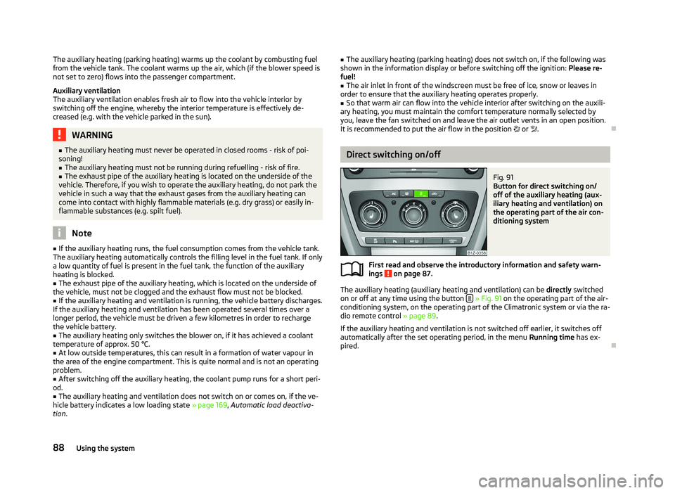
Fig. 91
Button for direct switching on/
off of the auxiliary heating (aux-
iliary heating and ventilation) on
the operating part of the air con-
ditioning system
First read and observe the introductory information and safety warn-
ings on page 87.
The auxiliary heating (auxiliary heating and ventilation) can be
directly switched
on or off at any time using the button » Fig. 91 on the operating part of the air-
conditioning system, on the operating part of the Climatronic system or via the ra-
dio remote control » page 89.
If the auxiliary heating and ventilation is not switched off earlier, it switches off
automatically after the set operating period, in the menu Running time has ex-
pired. Ð
ä
88 Using the system
Page 91 of 218
System settings
First read and observe the introductory information and safety warn-
ings on page 87.
The following menu items can be selected in the menu
Aux. heating in the infor-
mation display (depending on the equipment fitted in the vehicle):
■ Day of the wk. - Set the current weekday.
■ Time- Set the desired running time in 5
minute increments. The running time
can be 10 to 60 minutes.
■ Mode - Set the desired heating/ventilation mode.
■ Starting time 1-3 - In each pre-set time, the day and the time (hour and minute)
can be set for switching on the auxiliary heating and/or ventilation. An empty
position can be found between Sunday and Monday when selecting the day. If
this empty position is selected, the activation is performed without taking into
account the day.
■ Activate - Enable pre-set mode.
■ Dectivate - Disable pre-set mode.
■ Factory setting - Restore factory setting.
■ Back - Return to main menu.
Only one programmed pre-set time can be active.
The last programmed pre-set time remains active.
After the auxiliary heating activates at the set time, it is necessary to pre-set a
time again.
If the pre-set menu is closed by selecting the menu item Back or if no changes
are made on the display for more than 10 seconds, the set values are stored, but
the pre-set time is not activated.
An warning light on the button »
Fig. 91
on page 88 is illuminated when the
system is running.
The running system deactivates after expiration of the operating period or can be
deactivated earlier by pressing the button to directly switch on/off the auxiliary
heating » Fig. 91 on page 88
or by using the radio remote control. Ð
ä Radio remote control
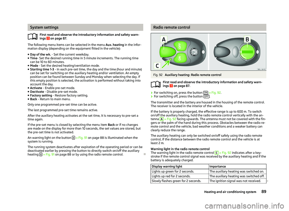
Fig. 92
Auxiliary heating: Radio remote control
First read and observe the introductory information and safety warn-
ings on page 87.
›
For switching on, press the button
ON » Fig. 92.
› For switching off, press the button
OFF .
The transmitter and the battery are housed in the housing of the remote control.
The receiver is located in the interior of the vehicle.
If the battery is properly charged, the effective range is up to 600
m. To switch
on/off the auxiliary heating, hold the radio remote control vertically with the an-
tenna A
» Fig. 92 facing upwards. The antenna must not be covered with the fin-
gers or the palm of the hand during this process. Obstacles between the radio re-
mote control and the vehicle, bad weather conditions and a weaker battery can
clearly reduce the range.
The auxiliary heating can only be switched on/off safely using the radio remote
control, if the distance between the radio remote control and the vehicle is at
least 2
m.
Warning light in the radio remote control
The warning light in the radio remote control C
» Fig. 92 indicates after a key-
stroke if the remote control signal was received by the auxiliary heating and if the
battery is adequately charged.
Display warning light Importance
Lights up green for 2 seconds. The auxiliary heating was switched on.
Lights up red for 2 seconds. The auxiliary heating was switched off.
Slowly flashes green for 2 seconds. The ignition signal was not received. £ ä
89
Heating and air conditioning system
Page 92 of 218
Display warning light
Importance
Quickly flashes green for 2 seconds. The auxiliary heating is blocked, e. g
because the tank is nearly empty or
there is a fault in the auxiliary heating.
Flashes red for 2 seconds. The switch off signal was not received.
Lights up orange for 2 seconds, then
green or red. The battery is weak, however the
switching on or off signal was received.
Lights up orange for 2 seconds, then
flashes green or red. The battery is weak, however the
switching on or off signal was not re-
ceived.
Flashes orange for 5 seconds. The battery is discharged, however the
switching on or off signal was not re-
ceived.CAUTION
The radio remote control comprises electronic components and must therefore be
protected against water, severe impacts and direct sunlight. ÐChanging the battery of the radio remote control
First read and observe the introductory information and safety warn-
ings on page 87.
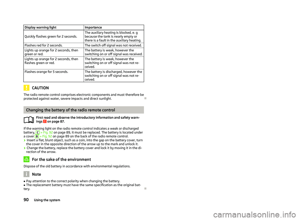
If the warning light on the radio remote control indicates a weak or discharged
battery, C
» Fig. 92 on page 89
, it must be replaced. The battery is located under
a cover B
» Fig. 92
on page 89 on the back of the radio remote control.
› Insert a flat, blunt object, such as a coin, into the gap on the battery cover, turn
the cover in the opposite direction of the arrow up to the mark and unlock it.
› Change the battery, replace the battery cover and lock it by moving it in the di-
rection of the arrow. For the sake of the environment
Dispose of the old battery in accordance with environmental regulations. Note
■ Pay attention to the correct polarity when changing the battery.
■ The replacement battery must have the same specification as the original bat-
tery. Ð
ä
90
Using the system
Page 193 of 218
Fuses in the engine compartment
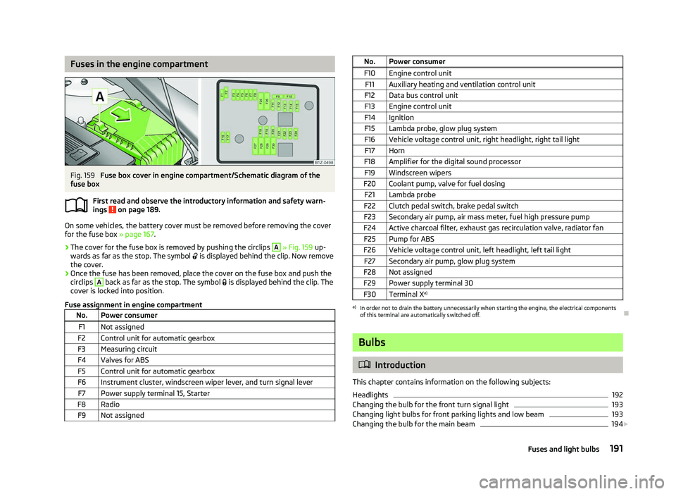
Fig. 159
Fuse box cover in engine compartment/Schematic diagram of the
fuse box
First read and observe the introductory information and safety warn-
ings on page 189.
On some vehicles, the battery cover must be removed before removing the cover
for the fuse box
» page 167.
› The cover for the fuse box is removed by pushing the circlips A
» Fig. 159
up-
wards as far as the stop. The symbol is displayed behind the clip. Now remove
the cover.
› Once the fuse has been removed, place the cover on the fuse box and push the
circlips A
back as far as the stop. The symbol
is displayed behind the clip. The
cover is locked into position.
Fuse assignment in engine compartment No. Power consumer
F1 Not assigned
F2 Control unit for automatic gearbox
F3 Measuring circuit
F4 Valves for ABS F5 Control unit for automatic gearbox
F6 Instrument cluster, windscreen wiper lever, and turn signal lever F7 Power supply terminal 15, Starter
F8 Radio F9 Not assigned ä
No. Power consumer
F10 Engine control unit F11 Auxiliary heating and ventilation control unit
F12 Data bus control unit
F13 Engine control unit
F14 Ignition F15 Lambda probe, glow plug system
F16 Vehicle voltage control unit, right headlight, right tail light F17 Horn
F18 Amplifier for the digital sound processor F19 Windscreen wipers
F20 Coolant pump, valve for fuel dosing F21 Lambda probe
F22 Clutch pedal switch, brake pedal switch
F23 Secondary air pump, air mass meter, fuel high pressure pump
F24 Active charcoal filter, exhaust gas recirculation valve, radiator fan F25 Pump for ABS
F26 Vehicle voltage control unit, left headlight, left tail light F27 Secondary air pump, glow plug system
F28 Not assigned F29 Power supply terminal 30
F30 Terminal X a) a)
In order not to drain the battery unnecessarily when starting the engine, the electrical components
of this terminal are automatically switched off. Ð Bulbs
ä
Introduction
This chapter contains information on the following subjects:
Headlights 192
Changing the bulb for the front turn signal light 193
Changing light bulbs for front parking lights and low beam 193
Changing the bulb for the main beam 194
£
191
Fuses and light bulbs
Page 210 of 218
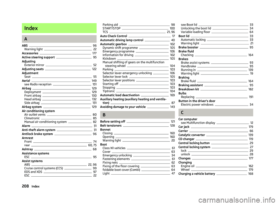
Index
A
ABS 96
Warning light 22
Accessories 177
Active steering support 95
Adjusting Exterior mirror 52
Adjusting seats 122
Adjustment Seat 55
Aerial 149
see Radio reception 151
Airbag 129
Deployment 129
Front airbag 130
Head airbag 132
Side airbag 131
Airbag system 129
Air conditioning system Air outlet vents 80
Climatronic 85
Manual air conditioning system 82
Alarm 31
Anti-theft alarm system 31
Antilock brake system 96
Armrest Front 74
rear 60, 75
Ashtray 68
Assistance systems ESC 95
Assist systems ABS 22, 96
Cruise control systems (CCS) 99
EDS and XDS 97
ESC 22Parking aid 98
START/STOP 100
TCS 21, 96
Auto Check Control 17
Automatic driving lamp control 40
Automatic gearbox 102
Dynamic shift programme 105
Emergency programme 106
Information for driving 102
Kickdown 105
Manual shifting of gears on the multifunction steering wheel 104
Parking 103
Selector lever-emergency unlocking 106
Selector lever lock 105
Selector lever positions 103
Starting off 103
Stopping 103
Tiptronic 104
Automatic load deactivation 169
Auxiliary heating (auxiliary heating and ventila- tion) 87
Avoiding damage to your vehicle 143
B
Before setting off 121
Belt tensioners 128
Bonnet Closing 160
Opening 160
Warning light 20
Boot Class
N1 vehicles 61
Cover 63
Emergency unlocking 34
Fastening elements 61
Fixing nets 62
Fixing of the floor covering 63
foldable boot cover (Combi) 64
Light 47see Boot lid 33
Unlocking the boot lid 34
Variable loading floor 64
Boot lid 33
Automatic locking 33
Warning light 21
Brake booster 95
Brake fluid Checking 164
Brakes Brake assist systems 93
Handbrake 95
Running in 139
Warning light 19
Braking Brake fluid 164
Braking assistant 95
Breakdown kit 182
Bulbs Replacing 191
Button in the driver's door Electric power windows 34
C
Car computer see Multifunction display 12
Car jack 179
Carrier 66
Catalytic converter 139
CD changer 119
Central locking button 29
Central locking system 27
lock 29
unlock 28
Changes 177
Changing Engine oil 162
Wheel 179
Charging a vehicle battery 168
208 Index