display SKODA OCTAVIA 2007 1.G / (1U) Owner's Guide
[x] Cancel search | Manufacturer: SKODA, Model Year: 2007, Model line: OCTAVIA, Model: SKODA OCTAVIA 2007 1.G / (1U)Pages: 288, PDF Size: 15.19 MB
Page 33 of 288
Instruments and Indicator/Warning Lights
32
The fact that the TCS system operates together with the ABS means that the TCS
warning light will also come on if the ABS system is not operating properly.
If the warning light
comes on immediately after starting the engine, the TCS
system can be switched off for technical reasons. In this case, the TCS system can
be switched on again by switching the ignition on and off. If the warning light goes
out, the TCS system is fully functional again.
Further information about the TCS ⇒page 183, “Traction control system (TCS)”.
Note
If the battery has been disconnected and reconnected, the warning light comes
on after switching on the ignition. The warning light must go out after driving a short
distance.
Electronic stability programme (ESP)*
The warning light comes on for a few seconds when the ignition is switched on.
Components of the ESP system also include the Traction Control System (TCS),
Electronic Differential Lock (EDL), and the Antilock Brake System ABS (ABS).
The warning light comes on when driving when a control cycle is activated.
The warning light will come on and remains on if the ESP is switched off or if there
is a fault in the system.
The fact that the ESP system operates together with the ABS means that the ESP
warning light will also come on if the ABS system is not operating properly.
If the warning light
comes on immediately after starting the engine, the ESP
system can be switched off for technical reasons. In this case, the ESP system can
be switched on again by switching the ignition on and off. If the warning light goes
out, the ESP system is fully functional again.
Further information on the ESP ⇒page 181, “Electronic stability programme
(ESP)*”. Electronic Differen
tial Lock (EDL)*
The EDL is a part of the ESP. A fault in th e EDL is indicated by the ESP warning light
in the instrument cluster. Have the ve hicle inspected without delay by a Škoda
Service Partner. Further information on the EDL ⇒page 182, “Electronic Differen-
tial Lock (EDS)*”.
Note
If the battery has been disconnected and reconnected, the warning light comes
on after switching on the ignition. The warning light must go out after driving a short
distance.
Alternator
The warning light comes on after the ignition has been switched on. It should go
out after the engine has started.
If the warning light does not go out after the engine has started, or comes on when
driving, drive to the nearest specialist garage. The vehicle battery will be discharged
in this case so switch off all non-essential electrical components.
Caution
If the warning light comes on when driving and in addition the warning light
(cooling system fault) also comes on in display, you must then stop the car imme-
diately and switch the engine off - risk of engine damage!
Brake system
The warning light flashes or comes on if the brake fluid level is too low, if there
is a fault in the ABS or if the handbrake is applied.
If the warning light
flashes (handbrake is not applied), stop and check the brake
fluid level ⇒ .
The following text will be displayed in the information display*: STOP Brake fluid Owner's manual
NKO A5 20 MR08.book Page 32 Wednesday, April 11, 2007 2:54 PM
Page 34 of 288
Instruments and Indicator/Warning Lights33
Using the systemSafetyDriving TipsGeneral MaintenanceBreakdown assistanceTechnical Data
If there is a fault in the ABS which also in
fluences the function of the normal brake
system (e.g. distribution of brake pressure), the ABS warning light
comes on
together with the brake system warning light . Be aware that not only the ABS but
also another part of th brake system is defective ⇒.
3 peeps sound as an additional warning signal.
One should get used to high pedal forces, long braking distances and long free play
of the brake pedal when driving to the next specialist garage.
For further information on the brake system ⇒page 184, “Brakes”.
Handbrake applied
The warning light
also comes on if the handbrake is applied. An audible warning
is also given if you drive the vehicle for at least 3 seconds at a speed of more than 6
km/h.
The following text will be displayed in the information display*:
Handbrake on!
WARNING
•Pay attention to the following instructions ⇒page 210, “Working in the
engine compartment” before checking the brake fluid level and opening the
bonnet.
•If the brake system warning light does not go out a few seconds after
switching on the ignition or comes on when driving, stop immediately and
check the brake fluid in the reservoir ⇒page 217, “Brake fluid”. If the fluid
level has dropped below the MIN marking, do not drive any further - risk of
accident! Contact a Škoda dealer to obtain professional assistance.
Seat belt warning light*
The warning light comes on after the ignition is switched on as a reminder to
fasten the seat belt. The warning light only goes out if the driver has fastened his
seat belt.
If the seat belt has not been fastened, a permanent warning signal sounds at vehicle
speeds greater than 20 km/h and simultaneously the warning light
flashes. If the seat belt is not fastened during
the next 90 seconds, the warning signal is
deactivated and the warning light
lights up permanently.
The following text will be displayed in the information display*: Please fasten seatbelt!
For further information on the seat belts ⇒page 158, “Seat belts”.
NKO A5 20 MR08.book Page 33 Wednesday, April 11, 2007 2:54 PM
Page 55 of 288
Lights and Visibility
54
Switching on Leaving Home Function
– Unlock the vehicle with the radio remote control - the lights come on.
Depending on equipment fitted the functi on Coming/Leaving Home switches on
the following lights:
•Parking lights,
•Low beam,
•Entry lighting in the exterior mirrors,
•Licence plate light.
Coming Home Function
The function Coming Home is only switch ed on, if the low beam was switched on
when the ignition is on.
The lights go out 30 seconds after cl osing all the doors and the boot lid.
If a door or the boot lid remains open, th e lights go out 30 seconds after switching
off the ignition.
The light switch remains in the position for low beam also after switching off the
Coming Home Function, all lights are automatically switched off.
On vehicles fitted with automatic driving la mp control you can also switch the light
switch in the position
⇒ page 51, fig. 39 . The function Coming Home is
controlled with the light sensor in the mount of the interior rear mirror. If the light
intensity is higher than the set value of the light sensor, the Coming Home Function
is not switched on after switching off the ignition.
Leaving Home Function
The function Leaving Home is controlled wi th the light sensor in the mount of the
interior rear mirror. If the light intensity is higher than the set value of the light
sensor, the Leaving Home Func tion is not switched on after unlocking the vehicle
with the radio remote control.
After unlocking the vehicle with the radio re mote control, the lights come on for 30
seconds. The Leaving Home Function is al so switched off after the ignition is
switched on and after locking the vehicle. If no door is opened within 30 seconds, th
e lights go out and the vehicle is locked
automatically.
Note
•If the Coming/Leaving Home Function is switched on constantly, the battery will
be heavily discharged particularly in short-haul traffic.
•The switching on of the described lights should only be undertaken in accord-
ance with the legal requirements.
•You can change the illumination period for the Coming/Leaving Home Function
by means of the information display* ⇒page 22.
Instrument lighting*
You can adjust the brightness of the instrument lighting.
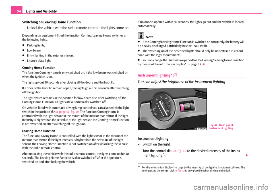
Instrument lighting
– Switch on the light.
– Turn the control dial ⇒fig. 42 to the desired intensity of the instru-
ment lighting
5).
5)For the information display* ⇒page 18 the intensity of the lighting is automatically set. The
setting using the control dial ⇒fig. 42 is only possible when driving in the dark.
Fig. 42 Dash panel:
Instrument lighting
NKO A5 20 MR08.book Page 54 Wednesday, April 11, 2007 2:54 PM
Page 57 of 288
Lights and Visibility
56
Note
Switch on the hazard warning light system if, for example:
•you encounter traffic congestion,
•your vehicle breaks down or an emergency situation occurs.
The turn signal and main beam lever
The parking lights and headlight flasher are also switched on and off
using the turn signal and main beam lever.
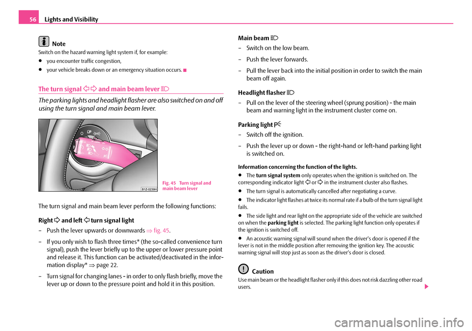
The turn signal and main beam lever perform the following functions:
Right
and left turn signal light
– Push the lever upwards or downwards ⇒fig. 45 .
– If you only wish to flash three times* (the so-called convenience turn signal), push the lever briefly up to the upper or lower pressure point
and release it. This function can be activated/deactivated in the infor-
mation display* ⇒page 22.
– Turn signal for changing lanes - in or der to only flash briefly, move the
lever up or down to the pressure point and hold it in this position. Main beam
– Switch on the low beam.
– Push the lever forwards.
– Pull the lever back into the initial po
sition in order to switch the main
beam off again.
Headlight flasher
– Pull on the lever of the steering wheel (sprung position) - the main beam and warning light in the instrument cluster come on.
Parking light
– Switch off the ignition.
– Push the lever up or down - the ri ght-hand or left-hand parking light
is switched on.
Information concerning the function of the lights.
•The turn signal system only operates when the ignition is switched on. The
corresponding indicator light or in the instrument cluster also flashes.
•The turn signal is automatically cancelled after negotiating a curve.
•The indicator light flashes at twice its normal rate if a bulb of the turn signal light
fails.
•The side light and rear light on the appr opriate side of the vehicle are switched
on when the parking light is selected. The parking light function only operates if
the ignition is switched off.
•An acoustic warning signal will sound when the driver's door is opened if the
lever is not in the middle position after removing the ignition key. The acoustic
warning signal will stop just as s oon as the driver's door is closed.
Caution
Use main beam or the headlight flasher only if this does not risk dazzling other road
users.
Fig. 45 Turn signal and
main beam lever
NKO A5 20 MR08.book Page 56 Wednesday, April 11, 2007 2:54 PM
Page 109 of 288
Heating and air conditioning system
108
For the sake of the environment
When you economize on fuel, you also reduce pollutant emissions.
Operational problems
If the cooling system does not operate at outside temperatures higher than +5 °C,
there is a problem in the system. The reasons for this may be:
•The fuse on the air conditioning system has blown. Check the fuse, replace it if
necessary ⇒page 243.
•The cooling system has switched off auto matically for a short time because the
coolant temperature of the engine is too hot ⇒ page 11.
If you are not able to rectify the operat ional problem yourself, or if the cooling
capacity decreases, switch the cooling system off. Contact a specialist garage.
Climatronic* (automatic air conditioning)
Description
The Climatronic system is a combin ation of an automatic heating,
fresh air and cooling system which provides optimal comfort for the
occupants of the car.
The Climatronic maintains a constant temperature fully automatically, once it has
been set. This is achieved by automa tically varying the temperature of the
outflowing air, the blower stages and the air distribution. The system also takes into
account bright sunlight which eliminates the need to alter the settings manually.
The automatic mode ⇒ page 110 ensures maximum wellbeing of the occupants
at all times of the year.
Description of Climatronic system
The cooling operates only if the following conditions are met:
•engine running,
•outside temperature above +2 °C,
•the button is not pressed.
If the cooling system is switched on, the temperature and air humidity drops in the
vehicle. The wellbeing of the occupants of the car is enhanced as a result of this
particularly at high outside temperatures and a high air humidity. The system
prevents the windows misting up during the cold season of the year.
The heating effect is dependent upon th e coolant temperature, thus full heat
output only occurs when the engine has reached its operating temperature.
It is possible to briefly activate recirculated air mode in order to enhance the
cooling effect ⇒.
The air inlet in front of the windscreen must be free of ice, snow or leaves in order
to ensure that the heating and cooling systems operate properly.
The AC compressor is switched off at a high coolant temperature in order to provide
cooling at a high load of the engine.
After switching on the cooling Condensation from the evaporator of the air condi-
tioning may drip down and form a puddle below the vehicle. This is quite normal
and not an indication of a leak!
Recommended setting for al l periods of the year:
•Set the temperature to 22 °C (72 °F).
•Press the button ⇒page 109, fig. 125 .
•Move the air outlet vents 3 and 4 so that the air flow is directed slightly upwards
⇒ page 112, fig. 126 .
Switching over between degrees Celsius and degrees Fahrenheit
Press and hold the buttons and ⇒page 109, fig. 125 . The informa-
tion in the desired temperature measuring unit appears in the display.
WARNING
•For your own safety and that of other road users, ensure that all the
windows are free of ice, snow and mist ing. Please familiarize yourself about
how to correctly operate the heating an d ventilation systems, how to demist
and defrost the windows, as well as with the cooling mode.
ECON
AUTO
ECONAUTO
NKO A5 20 MR08.book Page 108 Wednesday, April 11, 2007 2:54 PM
Page 110 of 288
Heating and air conditioning system109
Using the systemSafetyDriving TipsGeneral MaintenanceBreakdown assistanceTechnical Data
•You should not leave recirculated air mode on over a longer period of
time, as “stale” air may result in fatigue in the driver and occupants, divert
your attention and also cause the windows to mist up. The risk of having an
accident increases. Switch recirculated air mode off as soon as the windows
begin misting up.
Note
•If the cooling system has not been switched on for a lengthy period, odours may
be produced at the evaporator because of deposits. Switch the cooling system on
at least once a month for approximately 5 minutes at the highest blower stage - also
during the cold season of the year - in order to remove such odours. Also open a
window for a short time.
•We recommend that you do not smoke in the vehicle when the recirculating air
mode is operating since the smoke which is drawn at the evaporator from the inte-
rior of the vehicle forms deposits in the evaporator of the air conditioning system.
This produces a permanent odour when the air conditioning system is operating
which can only be eliminated through co nsiderable effort and expense (replace-
ment of compressor).
•The used air streams out through the air removal openings in the luggage
compartment.
•The Information of the Climatronic is displayed on the display of the radio*. You
can also switch off this function - see operating instructions for radio
•Using the cooling economically ⇒page 107.
•Operational problems ⇒page 108.
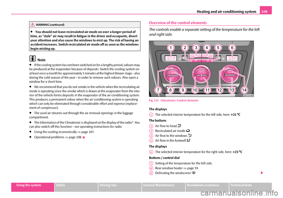
Overview of the control elements
The controls enable a separate sett ing of the temperature for the left
and right side.
Fig. 125 Climatroni c: Control elements
The displays
The selected interior temperature for the left side, here: +21 °C
The buttons Air flow to head
Recirculated air mode
Air flow to the windows
Air flow in the footwell
The displaysThe selected interior temperature for the right side, here: +23 °C
Buttons / control dial Setting of the temperature for the left side.
Rear window heater ⇒page 59
Defrosting the windscreen
WARNING (continued)
A1
A2
A3
A4
A5
A6
A7
A8
A9
NKO A5 20 MR08.book Page 109 Wednesday, April 11, 2007 2:54 PM
Page 111 of 288
Heating and air conditioning system
110
Control dial for:
− Setting of blower speed and
− Switching off the Climatronic
Button for direct switching on/off of auxiliary heating* ⇒page 113
Setting of the temperature for the right side.
Button for switching off cooling system
Automatic mode
Note
The interior temperature sensor is located in the centre of the control dial for
blower speed . Do not glue or cover over the sensor, otherwise it could have an
unfavourable effect on the Climatronic.
Automatic mode
The automatic mode is used in orde r to maintain a constant temper-
ature and to demist the windows in the interior of the car.
Switching automatic mode on
– Set a temperature between +16 °C (60 °F) and +29,5 °C (85 °F).
– Move the air outlet vents 2 and 3 ⇒ page 112, fig. 126 so that the air
flow is directed slightly upwards.
– Press the button - the warning light lights up in the button.
The automatic mode is switched off by pressing the button for the air distribution
or increasing or decreasing the blower speed. The temperature is nevertheless
regulated.
ECON mode
The cooling system is switched off in the ECON mode - heating and
ventilation are regulated automatically.
Switching ECON mode on
– Press the button - the warning light lights up in the button.
– Set a temperature between +16 °C (60 °F) and +29,5 °C (85 °F).
Recirculated air mode in ECON mode
– First of all press the button - the warning light lights up in the button.
– Then press the button - the warning light lights up in the button.
ECON mode operates only within the control temperature range from +16 °C (60
°F) up to +29.5 °C (85 °F).
The ECON mode is switched off when pressing button or .
Please note that, in the ECON mode, the interior temperature cannot be lower than
the outside temperature. The interior is no t cooled and the air is not dehumidified.
If you select the temperature below +16 °C (60 °F), LO appears in the display. If you
select a temperature higher than +29,5 °C (85 °F), HI appears in the display. In the
position LO the recirculated air is not warmed up. In the HI position, the system
operates continuously with maximum heating capacity.
Please refer to the information regarding recirculated air mode ⇒page 111.
Defrosting windscreen
Defrosting windscreen - switching on
– Press the button ⇒ page 109, fig. 125.
A10
A11
A12
A13ECON
A14
A10
AUTO
ECON
ECON
NKO A5 20 MR08.book Page 110 Wednesday, April 11, 2007 2:54 PM
Page 112 of 288
Heating and air conditioning system111
Using the systemSafetyDriving TipsGeneral MaintenanceBreakdown assistanceTechnical Data
Defrosting windscreen - switching off
– Once again press the button or the button .
The temperature control is controlled automatically. More air flows out of the air
outlet vents 1 and 2.
Recirculated air mode
In recirculated air mode air is sucked out of the interior of the vehicle
and then fed back into the interior.
Recirculated air mode prevents polluted air outside the vehicle from
getting into the vehicle, for example when driving through a tunnel or
when standing in a traffic jam.
Switching recirculated air mode on
– Press the button - the warning light lights up in the button.
Switching recirculated air mode off
– Press again the button or the button - the warning light in
the button goes out.
WARNING
You should not leave recirculated air mode on over a longer period of time,
as “stale” air may result in fatigue in the driver and occupants, divert your
attention and also cause the windows to mist up. The risk of having an acci-
dent increases. Switch recirculated air mode off as soon as the windows
begin misting up.
Note
If the windscreen mists up, press the button ⇒page 109, fig. 125 . After the
windscreen has been demisted, press the button .
Setting temperature
You can separate the interior temperature for the left and right side sepa-
rately.
– You can set the temperature for both sides after switching on the igni- tion with the control dial .
– If you wish to set the temperature for the right side, turn the control dial .
If the temperature for the right side was set via the control dial , it can no longer
be set via the control dial - temperature fo r both sides. This is only possible if
you press the button for about 2 seconds.
You can set the interior temperature between +16 °C (60 °F) and +29,5 °C (85 °F).
The interior temperature is regulated automatically within this range. If you select
the temperature below +16 °C (60 °F), “LO” appears in the display. If you select the
temperature higher than +29,5 °C (85 °F), “HI” appears in the display. In both limit
positions the Climatronic operates at maximum cooling or heating capacity,
respectively. The temperature is not controlled in this case.
Lengthy and uneven distribution of the air flow out of the vents (in particular at the
leg area) and large differences in temperat ure, for example when getting out of the
vehicle, can result in chills in sensitive persons.
Controlling blower
There are a total of seven blower stages available.
The Climatronic system controls the bl ower stages automatically in line
with the interior temperature. You can also, however, adapt the blower
stages manually to suit your particular needs.
– Turn the control dial ⇒page 109, fig. 125 to the left (reduce
blower speed) or right (increase blower speed).
Switch off the blowers, the Climatronic is switched off and in the display shows OFF.
AUTO
AUTO
A9AUTO
A7
A11
A11A7AUTO
A10
NKO A5 20 MR08.book Page 111 Wednesday, April 11, 2007 2:54 PM
Page 113 of 288
Heating and air conditioning system
112
The set blower speed is displayed above the control dial when the respective
number of warning lights come on.
WARNING
•“Stale air” may result in fatigue in the driver and occupants, reduce
attention levels and also cause the windows to mist up. The risk of having an
accident increases.
•Do not switch the Climatronic system off for longer than necessary.
•Switch the Climatronic system on as soon as the windows mist up.
Air outlet vents
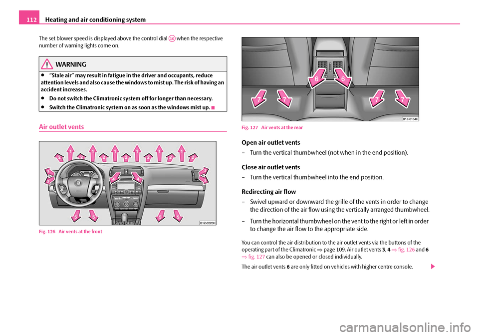
Fig. 126 Air vents at the front Fig. 127 Air vents at the rear
Open air outlet vents
– Turn the vertical thumbwheel (not when in the end position).
Close air outlet vents
– Turn the vertical thumbwheel into the end position.
Redirecting air flow
– Swivel upward or downward the grille of the vents in order to change
the direction of the air flow using the vertically arranged thumbwheel.
– Turn the horizontal thumbwheel on the vent to the right or left in order to change the air flow to the appropriate side.
You can control the air distribution to the air outlet vents via the buttons of the
operating part of the Climatronic ⇒page 109. Air outlet vents 3, 4 ⇒ fig. 126 and 6
⇒ fig. 127 can also be opened or closed individually.
The air outlet vents 6 are only fitted on vehicles with higher centre console.
A10
NKO A5 20 MR08.book Page 112 Wednesday, April 11, 2007 2:54 PM
Page 114 of 288
Heating and air conditioning system113
Using the systemSafetyDriving TipsGeneral MaintenanceBreakdown assistanceTechnical Data
Note
The air outlet vents 2 ensure in the ventilation and cooling mode for a comfortable
(no-draught) ventilation of th e interior of the vehicle, also if the air outlet vents 4
are closed.
Auxiliary heating system (auxiliary heating and
ventilation)*
Description
The auxiliary heating (auxiliary heating and ventilation) heats or
supplies the interior of the vehicl e with fresh air independent of the
engine.
Auxiliary heating (auxiliary heating)
The auxiliary heating (auxiliary heating) f unctions in connection with the heater or
with the Climatic or Climatronic.
It can be used when stationa ry, when engine is switched off for preheating of the
vehicle as well as while driving (e.g. during the heating phase of the engine).
The auxiliary heating (auxiliary heating) warms up the coolant during the combus-
tion of fuel from the vehicle tank. The cool ant warms up the air, which (if the blower
speed is not set to zero) flows into the occupant compartment.
6)
Auxiliary ventilation
The auxiliary ventilation enables fresh air to flow into the vehicle interior by
switching on the blower, if the blower speed is not set to zero, whereby the interior
temperature is effectively decreased (e.g. with a vehicle parked in the sun).
Using the system
So that the auxiliary heating (auxiliary heating and ventilation) func-
tions according to your expectations, it is necessary to carry out the
basic setting before its programming.
Basic setting
– In the information display, select from the menu Main menu the
Menu Setup (settings) ⇒ page 19, fig. 11 .
– In the menu Settings select the menu Aux. Heating (auxiliary
heating).
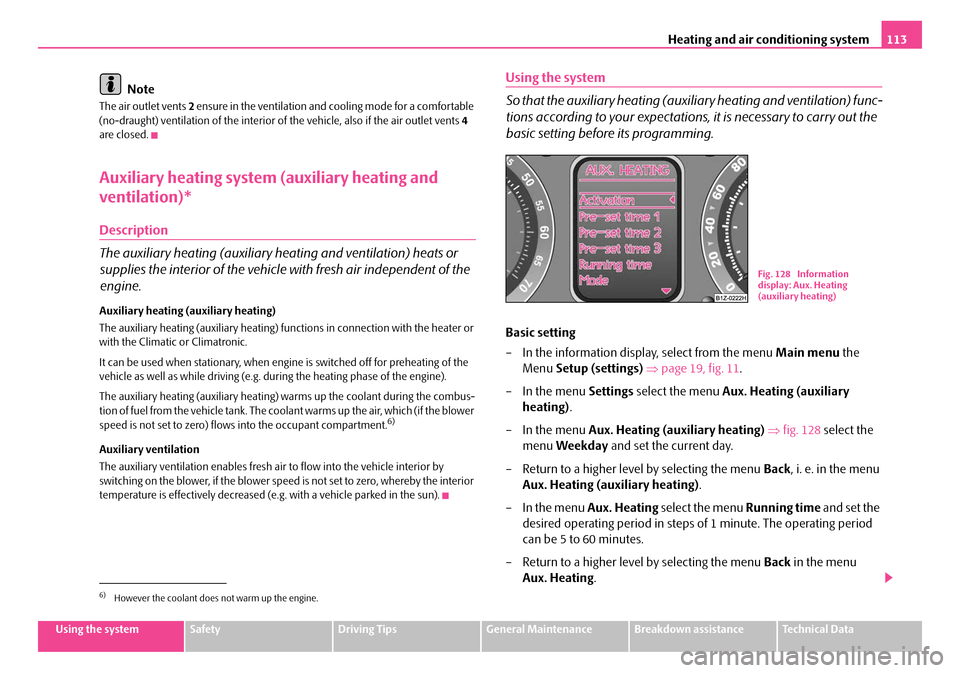
– In the menu Aux. Heating (auxiliary heating) ⇒ fig. 128 select the
menu Weekday and set the current day.
– Return to a higher level by selecting the menu Back, i. e. in the menu
Aux. Heating (auxiliary heating) .
– In the menu Aux. Heating select the menu Running time and set the
desired operating period in steps of 1 minute. The operating period
can be 5 to 60 minutes.
– Return to a higher level by selecting the menu Back in the menu
Aux. Heating .
6)However the coolant does not warm up the engine.
Fig. 128 Information
display: Aux. Heating
(auxiliary heating)
NKO A5 20 MR08.book Page 113 Wednesday, April 11, 2007 2:54 PM