technical data SKODA OCTAVIA 2007 1.G / (1U) Owner's Guide
[x] Cancel search | Manufacturer: SKODA, Model Year: 2007, Model line: OCTAVIA, Model: SKODA OCTAVIA 2007 1.G / (1U)Pages: 288, PDF Size: 15.19 MB
Page 68 of 288
Seats and Stowage67
Using the systemSafetyDriving TipsGeneral MaintenanceBreakdown assistanceTechnical Data
Seats and Stowage
Front seats
Basic information
The front seats have a wide range of differ ent settings and can thus be matched to
the physical characteristics of the driver and front passenger. Correct adjustment of
the seats is particularly important for
•safely and quickly reaching the controls,
•a relaxed, fatigue-free body position,
•achieving the maximum protection offere d by the seat belts and the airbag
system.
WARNING
•Never transport more occupants than the maximum seating in the
vehicle.
•Each occupant must correctly fasten the seat belt belonging to the seat.
Children must be fastened ⇒page 173, “Transporting children safely” with
a suitable restraint system.
•The front seats and the head restraints must always be adjusted to match
the body size of the seat occupant as well as the seat belts must always be
correctly fastened in order to provide an optimal protection for you and your
occupants.
•Always keep your feet in the footwell when the car is being driven - never
place your feet on the instrument panel, out of the window or on the
surfaces of the seats. This is particularly important for the front seat
passenger. You will be exposed to increa sed risk of injury if it becomes
necessary to apply the brake or in the ev ent of an accident. If an airbag is
deployed, you may suffer fatal injuries when adopting an incorrect seated
position!
•It is important for the driver and front passenger to maintain a distance
of at least 25 cm from the steering wheel or dash panel. Not maintaining this minimum distance will mean that the airb
ag system will not be able to prop-
erly protect you - hazard! The front seats and the head restraints must
always also be correctly adjusted to match the body size of the occupant.
•Ensure that there are no objects in the footwell as any objects may get
behind the pedals during a driving or braking manoeuvre. You would then
no longer be able to operate the clutch, to brake or accelerate.
Adjusting the front seats
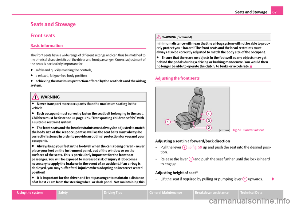
Adjusting a seat in a forward/back direction
–Pull the lever ⇒fig. 59 up and push the seat into the desired posi-
tion.
– Release the lever and push the seat further until the lock is heard to engage.
Adjusting height of seat*
– Lift the seat if required by pulling or pumping lever upwards.
WARNING (continued)
Fig. 59 Controls at seat
A1
A1
A2
NKO A5 20 MR08.book Page 67 Wednesday, April 11, 2007 2:54 PM
Page 70 of 288
Seats and Stowage69
Using the systemSafetyDriving TipsGeneral MaintenanceBreakdown assistanceTechnical Data
WARNING
•Only adjust the driver seat when the ve hicle is stationary - risk of injury!
•Caution when adjusting the seat! You ma y suffer injuries or bruises as a
result of adjusting the seat without paying proper attention.
•In view of the fact that the seats can also be adjusted when the ignition is
switched off (even when ignition key withdrawn), you should never leave
children unattended in the car.
•The backrests must not be angled too far back when driving otherwise
this will affect proper operation of the seat belts and of the airbag system -
risk of injury!
Note
If the movement of the seat is inadvertentl y interrupted during an adjustment, once
again press the switch in the appropriate direction and continue with the adjust-
ment of the seat to the end.
Storing setting
Storing seat and exterior mirror settings for driving forward
– Switch on the ignition. – Adjust the seat
⇒page 68.
– Adjust both exterior mirrors ⇒page 65.
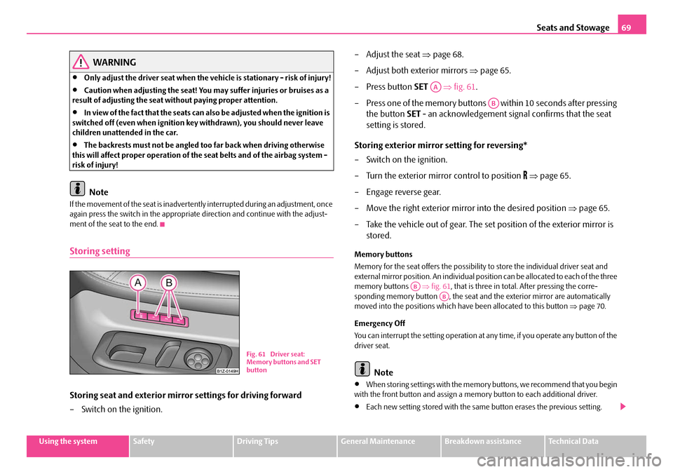
–Press button SET ⇒fig. 61 .
– Press one of the memory buttons within 10 seconds after pressing the button SET - an acknowledgement signal confirms that the seat
setting is stored.
Storing exterior mirror setting for reversing*
– Switch on the ignition.
– Turn the exterior mirror control to position
⇒ page 65.
– Engage reverse gear.
– Move the right exterior mirror into the desired position ⇒page 65.
– Take the vehicle out of gear. The set position of the exterior mirror is stored.
Memory buttons
Memory for the seat offers the possibility to store the individual driver seat and
external mirror position. An individual posi tion can be allocated to each of the three
memory buttons ⇒fig. 61 , that is three in total. After pressing the corre-
sponding memory button , the seat and the exterior mirror are automatically
moved into the positions which have been allocated to this button ⇒page 70.
Emergency Off
You can interrupt the setting operation at an y time, if you operate any button of the
driver seat.
Note
•When storing settings with the memory buttons, we recommend that you begin
with the front button and assign a memo ry button to each additional driver.
•Each new setting stored with the same button erases the previous setting.
Fig. 61 Driver seat:
Memory buttons and SET
button
AA
AB
ABAB
NKO A5 20 MR08.book Page 69 Wednesday, April 11, 2007 2:54 PM
Page 72 of 288
Seats and Stowage71
Using the systemSafetyDriving TipsGeneral MaintenanceBreakdown assistanceTechnical Data
Head restraints
Best protection is achieved if the top edge of the head restraint is at the
same level as the upper part of your head.
Adjusting the height of a head restraint
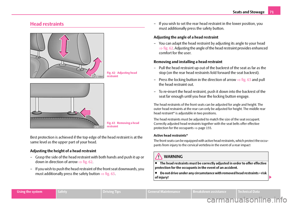
– Grasp the side of the head restraint with both hands and push it up or
down in direction of arrow ⇒fig. 62 .
– If you wish to push the head restra int of the front seat downwards, you
must additionally press the safety button ⇒fig. 63 . – If you wish to set the rear head restraint in the lower position, you
must additionally press the safety button.
Adjusting the angle of a head restraint
– You can adapt the head restraint by adjusting its angle to your head
⇒ fig. 62 . Adjusting the angle of the head restraint provides enhanced
comfort for the user.
Removing and installing a head restraint
– Pull the head restraint up out of the backrest of the seat as far as the
stop (on the rear head restraints fold forward the seat backrest).
– Press the locking button in the direction of arrow ⇒fig. 63 and pull
the head restraint out.
– To re-insert the head restraint, push it down into the backrest of the
seat far enough until you hear the locking button engage.
The head restraints of the front seats can be adjusted for angle and height. The
outer head restraints at the rear can only be adjusted for height. The middle rear
head restraint* is adjustable in two positions.
The head restraints must be adjusted to match the size of the seat occupant.
Correctly adjusted head restraints together with the seat belts offer effective
protection for the occupants ⇒page 155.
Active head restraints*
The front seats can be equipped with active head restraints, which protect the occu-
pants from injury to the cervical vertebra in the event of a rear impact
WARNING
•The head restraints must be correctly adjusted in order to offer effective
protection for the occupants in the event of an accident.
•Do not drive under any circumstance with removed head restraints - risk
of injury!
Fig. 62 Adjusting head
restraint
Fig. 63 Removing a head
restraint
NKO A5 20 MR08.book Page 71 Wednesday, April 11, 2007 2:54 PM
Page 74 of 288
Seats and Stowage73
Using the systemSafetyDriving TipsGeneral MaintenanceBreakdown assistanceTechnical Data
Rear seats
Folding the rear seats forwards
To enlarge the luggage compartment , the rear seats can be folded
forwards, if necessary remove the rear seats. The rear seats can be folded
forward individually on vehicl es with divided rear seats*.
Folding the rear seats forwards
– Before folding the rear seats forwar d adjust the front seats in such a
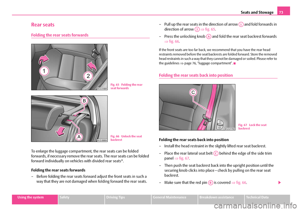
way that they are not damaged when folding forward the rear seats. – Pull up the rear seats in the direction of arrow and fold forwards in
direction of arrow ⇒ fig. 65.
– Press the unlocking knob and fold the rear seat backrest forwards ⇒fig. 66 .
If the front seats are too far back, we recommend that you have the rear head
restraints removed before the seat backrests are folded forward. Store the removed
head restraints in such a way that they cannot be damaged or soiled. Please refer to
the guidelines ⇒page 76, “luggage compartment”.
Folding the rear seats back into position
Folding the rear seats back into position
– Install the head restraint in the slightly lifted rear seat backrest.
– Place the rear lateral seat belt behind the edge of the side trim
panel ⇒fig. 67 .
– Then push the seat backrest back into the upright position until the
securing knob clicks into place - check by pulling on the rear seat
backrest.
– Make sure that the red pin is covered ⇒fig. 66 .
Fig. 65 Folding the rear
seat forwards
Fig. 66 Unlock the seat
backrest
A1
A2
AA
Fig. 67 Lock the seat
backrest
AC
AB
NKO A5 20 MR08.book Page 73 Wednesday, April 11, 2007 2:54 PM
Page 76 of 288
Seats and Stowage75
Using the systemSafetyDriving TipsGeneral MaintenanceBreakdown assistanceTechnical Data
Seat heaters*
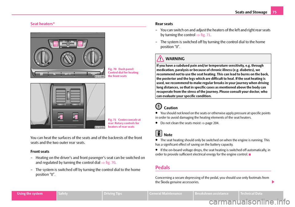
You can heat the surfaces of the seats and of the backrests of the front
seats and the two outer rear seats.
Front seats
– Heating on the driver's and front pasenger's seat can be switched on
and regulated by turning the control dial ⇒fig. 70 .
– The system is switched off by turning the control dial to the home position “0”. Rear seats
– You can switch on and adjust the heaters of the left and right rear seats
by turning the control ⇒fig. 71 .
– The system is switched off by turning the control dial to the home position “0”.
WARNING
If you have a subdued pain and/or te mperature sensitivity, e.g. through
medication, paralysis or because of ch ronic illness (e.g. diabetes), we
recommend not to use the seat heating. This can lead to burns on the back,
the posterior and the legs which are difficult to he al. If the seat heating is
used, we recommend to make regular breaks in your journey when driving
long distances, so that in specific cases as mentioned above the body can
recuperate from the stress of the journey. Please consult your doctor, who
can evaluate your specific condition.
Caution
•You should not kneel on the seats or othe rwise apply pressure at specific points
in order to avoid damaging the heating elements of the seat heaters.
•Do not clean the seats moist ⇒page 204.
Note
•The seat heating should only be switched on when the engine is running. This
has a significant effect of sa ving on the battery capacity.
•If the on-board voltage drops, the seat heating is switched off automatically, in
order to provide sufficient electrical energy for the engine control.
Pedals
Concerning a secure depressing of the pe dal, you should use only footmats from
the Škoda genuine accessories.
Fig. 70 Dash panel:
Control dial for heating
the front seats
Fig. 71 Centre console at
rear: Rotary controls for
heaters of rear seats
NKO A5 20 MR08.book Page 75 Wednesday, April 11, 2007 2:54 PM
Page 78 of 288
Seats and Stowage77
Using the systemSafetyDriving TipsGeneral MaintenanceBreakdown assistanceTechnical Data
Lashing eyes
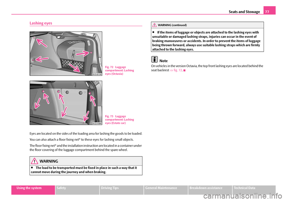
Eyes are located on the sides of the loading area for lashing the goods to be loaded.
You can also attach a floor fixing net* to these eyes for lashing small objects.
The floor fixing net* and the installation instruction are located in a container under
the floor covering of the luggage compartment behind the spare wheel.
WARNING
•The load to be transported must be fi xed in place in such a way that it
cannot move during the journey and when braking.
•If the items of luggage or objects ar e attached to the lashing eyes with
unsuitable or damaged lashing straps, injuries can occur in the event of
braking manoeuvres or accidents. In order to prevent the items of luggage
being thrown forward, always use suit able lashing straps which are firmly
attached to the lashing eyes.
Note
On vehicles in the version Octavia, the top front lashing eyes are located behind the
seat backrest ⇒fig. 72 .Fig. 72 Luggage
compartment: Lashing
eyes (Octavia)
Fig. 73 Luggage
compartment: Lashing
eyes (Estate car)
WARNING (continued)
NKO A5 20 MR08.book Page 77 Wednesday, April 11, 2007 2:54 PM
Page 80 of 288

Seats and Stowage79
Using the systemSafetyDriving TipsGeneral MaintenanceBreakdown assistanceTechnical Data
WARNING
The whole strength of the net makes it possible to load the pocket with
objects of up to 1.5 kg in weight. Heavy objects are not secured sufficiently -
risk of injury and net damage!
Caution
Do not place any objects with sharp edge s in the nets - risk of net damage.
Folding double hooks* (Octavia)
Folding double hooks for attaching small items of luggage, such as bags etc.
⇒ fig. 78 are provided on one or both sides of the luggage compartment
depending on the equipment installed in the vehicle.
An item of luggage weighing up to 5 kg can be attached to each side of the double
hook.
Folding hooks (Combi)
Folding hooks for attaching small items of luggage, such as bags etc., are provided
on both sides of the luggage compartment ⇒fig. 79 .
An item of luggage weighing up to 10 kg can be attached to the hook.
Fig. 78 Luggage
compartment: Folding
double hooks
Fig. 79 Luggage
compartment: folding
hooks
NKO A5 20 MR08.book Page 79 Wednesday, April 11, 2007 2:54 PM
Page 82 of 288

Seats and Stowage81
Using the systemSafetyDriving TipsGeneral MaintenanceBreakdown assistanceTechnical Data
Luggage compartment cover* (Octavia)
You can use the luggage compartment cover behind the head
restraints for storing light and soft items.
The luggage compartment cover can be removed as required if one must
transport bulky goods.
– Unhook the support straps on the boot lid ⇒fig. 83 .
– Place the cover on the side supports.
– Pull the cover out of the holder horizontally to the rear.
– Install again by pushing the luggage compartment cover forwards into
the holder and hanging the suppo rt straps on the boot lid.
You can stow the removed luggage compartment cover behind the rear seat back-
rest.
WARNING
No objects should be placed on the luggage compartment cover, the vehicle
occupants could be endangered if th ere is sudden braking or the vehicle
collides with something.
Caution
Please ensure that the heating elements of the rear window heater are not
damaged as a result of obje cts placed in this area.
Note
Opening the tailgate also lifts up the luggage compartment cover.
Luggage compartment cover (estate car)
Fig. 83 Removing the
luggage compartment
cover
A1
A2
A2A1
Fig. 84 Luggage
compartment: The
luggage compartment
cover
Fig. 85 Luggage
compartment: Removing
the luggage compart-
ment cover
NKO A5 20 MR08.book Page 81 Wednesday, April 11, 2007 2:54 PM
Page 84 of 288

Seats and Stowage83
Using the systemSafetyDriving TipsGeneral MaintenanceBreakdown assistanceTechnical Data
– In the same way, fix the cross rod to the other side of the vehicle,
mount .
– Fold the stowage compartment cover downwards.
Rolling up
– Fold down the stowage compartment cover behind the rear seats ⇒fig. 86 .
– Pull the cross rod back slightly, first on the one side then on the other side and take the cross rod out of the mount ⇒fig. 87 .
– Hold the cross rod in such a way that the net partition can roll up
slowily and without damage into housing .
– Fold the stowage compartment cover downwards.
If you wish to use the entire luggage compartment, you can remove the luggage
compartment cover ⇒page 81, fig. 84 .
WARNING
•First check for yourself that the cross road is inserted into the mounts
in the front position!
•Pay attention that the rear seat backrest is correctly interlocked. It is only
then that the three-point seat belt for the middle seat can reliably fulfil its
function.
Use behind the front seats
Unrolling
– Fold the rear seats forwards ⇒page 73
– Pull the net partiton net at the plate out of the housing ⇒fig. 88 .
– Insert the cross rod into the mount first on the one side and push the cross rod forward.
– In the same way, fix the cross rod to the other side of the vehicle, mount .
Rolling up
– Pull the cross rod back slightly, first on the one side then on the other side and take the cross rod out of the mount ⇒fig. 88 .
– Hold the cross rod in such a way that the net partition can roll up
slowily and without damage into housing .
– Fold the rear seats back into its original position.
AC
AC
AB
AC
Fig. 88 Unrolling net
partition
AAAB
AC
AC
AC
AB
NKO A5 20 MR08.book Page 83 Wednesday, April 11, 2007 2:54 PM
Page 86 of 288

Seats and Stowage85
Using the systemSafetyDriving TipsGeneral MaintenanceBreakdown assistanceTechnical Data
For the sake of the environment
The increased aerodynamic drag results in a higher fuel consumption. One should
therefore take off the roof bar system after use.
Note
A roof rail is obtainable from a specialist garage if hasn't been fitted onto an estate
car at the works.
Lashing points (Octavia)
Fitting
– Insert the attachment points of th e roof rack into the mounts of the
body so that the pins of the attachment points grasp into the holes of
the body.
Note
•Pay attention to the information regarding assembly and disassembly in the
attached instructions.
•If you have any questions, plea se contact a specialist garage.
•The figure is not valid for an estate car.
Roof load
Distribute weight evenly over the roof luggage rack system. The maximum permis-
sible roof load (including roof rack system) of 75 kg and the maximum permissible
total weight of the vehicl e should not be exceeded.
You cannot make full use of th e permissible roof load if you use a roof luggage rack
system with a lower load carrying capa city. The load transported on the roof
luggage rack system must not exceed the weight limit which is stated in the fitting
instructions.
WARNING
•The items which you transport on the roof bar system must be reliably
attached - risk of accident!
•You must on no account exceed the permissible roof load, the permis-
sible axle loads and the permissible gross weight of your vehicle - risk of
accident!
•Please note that the handling properties of your vehicle change when
you transport heavy or bulky items on the roof bar system as a result of the
displacement of the centre of gravity and the increased wind attack area -
risk of accident! You must absolutely adapt your style of driving and the
speed of the vehicle to the specific circumstances.
Fig. 90 Attachment
points for base roof
carrier
NKO A5 20 MR08.book Page 85 Wednesday, April 11, 2007 2:54 PM