display SKODA OCTAVIA 2008 2.G / (1Z) Owner's Manual
[x] Cancel search | Manufacturer: SKODA, Model Year: 2008, Model line: OCTAVIA, Model: SKODA OCTAVIA 2008 2.G / (1Z)Pages: 304, PDF Size: 17.69 MB
Page 4 of 304
Contents3
Using the systemSafetyDriving TipsGeneral MaintenanceBreakdown assistanceTechnical Data
Contents
Layout of this Owner's Manual
(explanations)
. . . . . . . . . . . . . . . . . . . . . . . . . .
Using the system. . . . . . . . . . . . . . . . . . . . . .
Cockpit. . . . . . . . . . . . . . . . . . . . . . . . . . . . . . . . . . . . . . . .
Overview . . . . . . . . . . . . . . . . . . . . . . . . . . . . . . . . . . . .
The brief instruction . . . . . . . . . . . . . . . . . . . . . . . . . .
Basic functions and important information . . . . .
Instruments and Indicator/Warning Lights. . .
General view of the instrument cluster . . . . . . . . .
Engine revolutions counter . . . . . . . . . . . . . . . . . . . .
Speedometer . . . . . . . . . . . . . . . . . . . . . . . . . . . . . . . .
Coolant temperature gauge . . . . . . . . . . . . . . . . . . .
Fuel gauge . . . . . . . . . . . . . . . . . . . . . . . . . . . . . . . . . . .
Counter for distance driven . . . . . . . . . . . . . . . . . . .
Service Interval Display . . . . . . . . . . . . . . . . . . . . . . .
Digital clock . . . . . . . . . . . . . . . . . . . . . . . . . . . . . . . . . .
Multi-functional indicato r (onboard computer)*
Information display* . . . . . . . . . . . . . . . . . . . . . . . . . .
Audio . . . . . . . . . . . . . . . . . . . . . . . . . . . . . . . . . . . . . . . .
Navigation system* . . . . . . . . . . . . . . . . . . . . . . . . . . .
Auto Check Control* . . . . . . . . . . . . . . . . . . . . . . . . . .
Warning lights . . . . . . . . . . . . . . . . . . . . . . . . . . . . . . . .
Unlocking and locking . . . . . . . . . . . . . . . . . . . . . . . .
Key . . . . . . . . . . . . . . . . . . . . . . . . . . . . . . . . . . . . . . . . . .
Key with light* . . . . . . . . . . . . . . . . . . . . . . . . . . . . . . . .
Changing the battery of the radio remote control
Electronic immobiliser . . . . . . . . . . . . . . . . . . . . . . . .
Child safety lock . . . . . . . . . . . . . . . . . . . . . . . . . . . . . .
Central locking system . . . . . . . . . . . . . . . . . . . . . . . .
Remote control* . . . . . . . . . . . . . . . . . . . . . . . . . . . . . . Synchonisation of the remote control . . . . . . . . . .
Anti-theft alarm system* . . . . . . . . . . . . . . . . . . . . . .
Power windows* . . . . . . . . . . . . . . . . . . . . . . . . . . . . .
Electric sliding/tilting roof* . . . . . . . . . . . . . . . . . . . .
Lights and Visibility . . . . . . . . . . . . . . . . . . . . . . . . . . .
Lights . . . . . . . . . . . . . . . . . . . . . . . . . . . . . . . . . . . . . . . .
Interior lighting . . . . . . . . . . . . . . . . . . . . . . . . . . . . . . .
Visibility . . . . . . . . . . . . . . . . . . . . . . . . . . . . . . . . . . . . .
Windshield wiper and wash system . . . . . . . . . . . .
Rear-view mirror . . . . . . . . . . . . . . . . . . . . . . . . . . . . .
Seats and Stowage. . . . . . . . . . . . . . . . . . . . . . . . . . . .
Front seats . . . . . . . . . . . . . . . . . . . . . . . . . . . . . . . . . . .
Adjusting front seats electrically* . . . . . . . . . . . . . .
Head restraints . . . . . . . . . . . . . . . . . . . . . . . . . . . . . . .
Middle rear head restraint* . . . . . . . . . . . . . . . . . . . .
Rear seats . . . . . . . . . . . . . . . . . . . . . . . . . . . . . . . . . . . .
Pedals . . . . . . . . . . . . . . . . . . . . . . . . . . . . . . . . . . . . . . .
luggage compartment . . . . . . . . . . . . . . . . . . . . . . . .
Net partition (Estate)* . . . . . . . . . . . . . . . . . . . . . . . .
The roof rack* . . . . . . . . . . . . . . . . . . . . . . . . . . . . . . . .
Cup holder . . . . . . . . . . . . . . . . . . . . . . . . . . . . . . . . . . .
Note holder . . . . . . . . . . . . . . . . . . . . . . . . . . . . . . . . . .
Ashtray* . . . . . . . . . . . . . . . . . . . . . . . . . . . . . . . . . . . . .
Cigarette lighter*, power sockets . . . . . . . . . . . . . . .
Storage compartments . . . . . . . . . . . . . . . . . . . . . . . .
Overview . . . . . . . . . . . . . . . . . . . . . . . . . . . . . . . . . . . .
Storage compartment on the front passenger side
Cooling of storage compartment on front
passenger side* . . . . . . . . . . . . . . . . . . . . . . . . . . . . . .
Storage compartment on the driver's side . . . . . .
Storage compartment on the dash panel* . . . . . .
Stowage compartment in front centre console* .
Storage net on the front centre console* . . . . . . . Stowage compartment for spectacles* . . . . . . . . .
Storage compartment in the front doors . . . . . . .
Stowage compartment below front passenger
seat* . . . . . . . . . . . . . . . . . . . . . . . . . . . . . . . . . . . . . . . .
Front seat armrest with storage compartment* .
Rear seat armrest with storage compartment* . .
Stowage compartment in rear centre console* .
Seat backrest with opening for skis* . . . . . . . . . . . .
Through-loading bag* . . . . . . . . . . . . . . . . . . . . . . . .
Side compartment* . . . . . . . . . . . . . . . . . . . . . . . . . .
Stowage compartment behind the rear seats
(estate car) . . . . . . . . . . . . . . . . . . . . . . . . . . . . . . . . . . .
Clothes hooks* . . . . . . . . . . . . . . . . . . . . . . . . . . . . . .
Heating and air conditioning system. . . . . . . . .
Air outlet vents . . . . . . . . . . . . . . . . . . . . . . . . . . . . . . .
Heating . . . . . . . . . . . . . . . . . . . . . . . . . . . . . . . . . . . . . .
Climatic* (semi-automatic air conditioning
system) . . . . . . . . . . . . . . . . . . . . . . . . . . . . . . . . . . . . . .
Climatronic* (automatic air conditioning) . . . . . .
Auxiliary heating (auxiliary heating and
ventilation)* . . . . . . . . . . . . . . . . . . . . . . . . . . . . . . . . .
Starting-off and Driving . . . . . . . . . . . . . . . . . . . . . .
Setting steering wheel position . . . . . . . . . . . . . . . .
Ignition lock . . . . . . . . . . . . . . . . . . . . . . . . . . . . . . . . .
Starting the engine . . . . . . . . . . . . . . . . . . . . . . . . . . .
Switching off the engine . . . . . . . . . . . . . . . . . . . . . .
Shifting (manual gearbox) . . . . . . . . . . . . . . . . . . . . .
Handbrake . . . . . . . . . . . . . . . . . . . . . . . . . . . . . . . . . . .
Rear parking aid* . . . . . . . . . . . . . . . . . . . . . . . . . . . . .
Front and rear parking aid* . . . . . . . . . . . . . . . . . . . .
Cruise control system (CCS)* . . . . . . . . . . . . . . . . . .
Automatic gearbox . . . . . . . . . . . . . . . . . . . . . . . . . . .
Automatic gearbox* . . . . . . . . . . . . . . . . . . . . . . . . . .
6
7
9
9
11
11
17
17
18
18
18
18
19
20
21
21
26
28
28
28
32
42
42
42
43
44
44
45
49 51
51
53
56
59
59
66
67
69
73
76
76
77
80
81
81
85
85
91
93
94
95
95
97
98
98
99
99
100
100
101
101 101
102
102
102
103
104
104
105
106
106
107
108
108
109
111
115
119
124
124
125
126
127
127
128
129
130
131
134
134
20A5Facelift.book Page 3 Saturday, September 6, 2008 2:13 PM
Page 18 of 304
Instruments and Indicator/Warning Lights17
Using the systemSafetyDriving TipsGeneral MaintenanceBreakdown assistanceTechnical Data
Instruments and Indicator/Warning Lights
General view of the instrument cluster
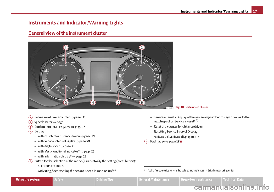
Engine revolutions counter ⇒page 18
Speedometer ⇒page 18
Coolant temperature gauge ⇒page 18
Display
− with counter for distance driven ⇒page 19
− with Service Interval Display ⇒page 20
− with digital clock ⇒page 21
− with Multi-functional indicator* ⇒page 21
− with Information display* ⇒page 26
Button for the selection of the mode (t urn button) / the setting (press button):
− Set hours / minutes
− Activating / deactivating the second speed in mph or km/h* −
Service interval - Display of the rema ining number of days or miles to the
next Inspection Se rvice / Reset* 1)
−Reset trip counter for distance driven
− Resetting Service Interval Display
− Activate / deactivate display mode
Fuel gauge ⇒page 18
Fig. 18 Instrument cluster
A1
A2
A3
A4
A5
1)Valid for countries where the values are indicated in British measuring units.
A6
20A5Facelift.book Page 17 Saturday, September 6, 2008 2:13 PM
Page 20 of 304
Instruments and Indicator/Warning Lights19
Using the systemSafetyDriving TipsGeneral MaintenanceBreakdown assistanceTechnical Data
The following will be displayed in the information display*:
Please refuel! (Please refuel!)
An audible signal sounds as an additional warning signal.
Caution
Never run the fuel tank completely empty! The irregular supply of the fuel system
can lead to irregular running of the engi ne. Unburnt fuel may get into the exhaust
system and damage the catalytic converter.
Note
After filling up, it can occur that during dynamic driving (e.g. numerous curves,
braking, accelerating and climbing a stee p hill) the fuel gauge indicates approx. a
fraction less. When stopping or during less dynamic driving, the correct fuel supply
quantity is indicated. Th is effect is not a fault.
Counter for distance driven
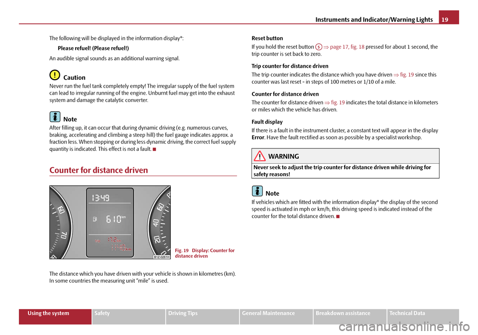
The distance which you have driven with your vehicle is shown in kilometres (km).
In some countries the measur ing unit “mile” is used. Reset button
If you hold the reset button
⇒page 17, fig. 18 pressed for about 1 second, the
trip counter is set back to zero.
Trip counter for distance driven
The trip counter indicates the di stance which you have driven ⇒fig. 19 since this
counter was last reset - in steps of 100 metres or 1/10 of a mile.
Counter for distance driven
The counter for distance driven ⇒fig. 19 indicates the total distance in kilometers
or miles which the vehicle has driven.
Fau lt dis pla y
If there is a fault in the instrument cluster, a constant text will appear in the display
Error . Have the fault rectified as soon as possible by a specialist workshop.
WARNING
Never seek to adjust the trip counter for distance driven while driving for
safety reasons!
Note
If vehicles which are fitted with the info rmation display* the display of the second
speed is activated in mph or km/h, this driving speed is indicated instead of the
counter for the total distance driven.
Fig. 19 Display: Counter for
distance driven
A5
20A5Facelift.book Page 19 Saturday, September 6, 2008 2:13 PM
Page 21 of 304
Instruments and Indicator/Warning Lights
20
Service Interval Display
Depending on the equipment installed in the vehicle, the text can differ on the
display.
Service Interval Display
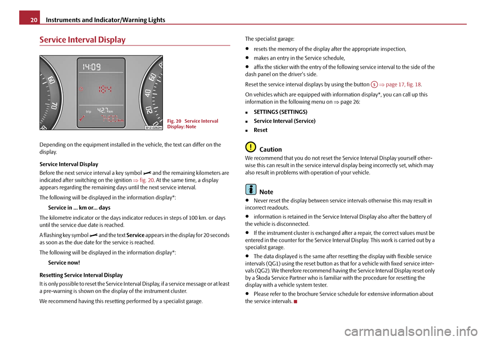
Before the next service interval a key symbol
and the remaining kilometers are
indicated after switching on the ignition ⇒fig. 20 . At the same time, a display
appears regarding the remaining days until the next service interval.
The following will be displayed in the information display*:
Service in ... km or... days
The kilometre indicator or the days indica tor reduces in steps of 100 km. or days
until the service due date is reached.
A flashing key symbol
and the text Service appears in the display for 20 seconds
as soon as the due date for the service is reached.
The following will be displayed in the information display*:
Service now!
Resetting Service Interval Display
It is only possible to reset the Service Interval Display, if a service message or at least
a pre-warning is shown on the display of the instrument cluster.
We recommend having this resetting performed by a specialist garage. The specialist garage:
•resets the memory of the display after the appropriate inspection,
•makes an entry in the Service schedule,
•affix the sticker with the entry of the following service interval to the side of the
dash panel on the driver's side.
Reset the service interval displays by using the button ⇒page 17, fig. 18 .
On vehicles which are equipped with in formation display*, you can call up this
information in the following menu on ⇒page 26:
�„SETTINGS (SETTINGS)
�„Service Interval (Service)
�„Reset
Caution
We recommend that you do not reset the Service Interval Display yourself other-
wise this can result in the service interval display being incorrectly set, which may
also result in problems with operation of your vehicle.
Note
•Never reset the display between service intervals otherwise this may result in
incorrect readouts.
•information is retained in the Service Interval Display also after the battery of
the vehicle is disconnected.
•If the instrument cluster is exchanged afte r a repair, the correct values must be
entered in the counter for the Service Interva l Display. This work is carried out by a
specialist garage.
•The data displayed is the same after resetting the display with flexible service
intervals (QG1) using the reset button as th at for a vehicle with fixed service inter-
vals (QG2). We therefore recommend having the Service Interval Display reset only
by a Škoda Service Partner who is familiar with the procedure for resetting the
display with a vehicle system tester.
•Please refer to the brochure Service schedule for extensive information about
the service intervals.
Fig. 20 Service Interval
Display: Note
A5
20A5Facelift.book Page 20 Saturday, September 6, 2008 2:13 PM
Page 22 of 304
Instruments and Indicator/Warning Lights21
Using the systemSafetyDriving TipsGeneral MaintenanceBreakdown assistanceTechnical Data
Digital clock
You can set the time with the rotary knob ⇒page 17, fig. 18 .
Select the information which you wish to change by turning the button and
carry out the change of the selected information by pressing the button.
On vehicles which are fitted out with the information display*, it is possible to set
the time in the menu Time ⇒ page 30.
WARNING
The clock should not be adjusted while driving for safety reasons but only
when the vehicle is stationary!
Multi-functional indicator (onboard computer)*
Introduction
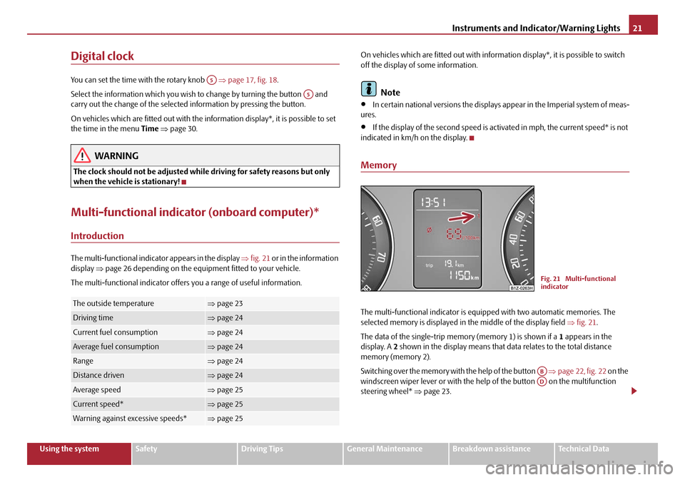
The multi-functional indica tor appears in the display ⇒fig. 21 or in the information
display ⇒page 26 depending on the equipment fitted to your vehicle.
The multi-functional indicator offers you a range of useful information. On vehicles which are fitted out with inform
ation display*, it is possible to switch
off the display of some information.
Note
•In certain national versions the displays appear in the Imperial system of meas-
ures.
•If the display of the second speed is acti vated in mph, the current speed* is not
indicated in km/h on the display.
Memory
The multi-functional indicator is equi pped with two automatic memories. The
selected memory is displayed in the middle of the display field ⇒ fig. 21.
The data of the single-trip memo ry (memory 1) is shown if a 1 appears in the
display. A 2 shown in the display means that da ta relates to the total distance
memory (memory 2).
Switching over the memory with the help of the button ⇒page 22, fig. 22 on the
windscreen wiper lever or with the help of the button on the multifunction
steering wheel* ⇒page 23.The outside temperature⇒page 23
Driving time⇒page 24
Current fuel consumption⇒page 24
Average fuel consumption⇒page 24
Range⇒page 24
Distance driven⇒page 24
Average speed⇒page 25
Current speed*⇒page 25
Warning against excessive speeds*⇒page 25
A5
A5
Fig. 21 Multi-functional
indicator
ABAD
20A5Facelift.book Page 21 Saturday, September 6, 2008 2:13 PM
Page 23 of 304
Instruments and Indicator/Warning Lights
22
Single-trip memory (memory 1)
The single-trip memory collates the driving information from the moment the igni-
tion is switched on until it is switched off. New data will also flow into the calcula-
tion of the current driving information if the trip is continued within 2 hours after
switching off the ignition. The memory will be is automatically erased, on the other
hand, if the trip is interrupted for more than 2 hours.
Total-trip memory (memory 2)
The total distance driven memory gathers data from any number of individual jour-
neys up to a total of 99 hours and 59 minutes driving or 9.999 kilometres driven.
The memory is deleted when either of these limits is reached and the calculation
starts from anew.
The total-trip memory will not, contrary to the single-trip memory, be deleted after
a period of interruption of driving of 2 hours.
Note
All information in the memory 1 and 2 is erased if the battery of the vehicle is
disconnected.
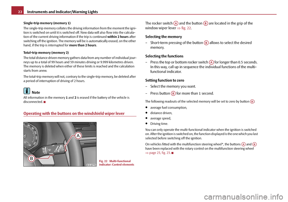
Operating with the buttons on the windshield wiper lever
The rocker switch and the button are located in the grip of the
window wiper lever ⇒fig. 22 .
Selecting the memory
– Short-term pressing of the button allows to select the desired
memory.
Selecting the functions
– Press the top or bottom rocker switch for longer than 0.5 seconds. In this way, call up in sequence the individual functions of the multi-
functional indicator.
Setting function to zero
– Select the memory you want.
– Press button for more than 1 second.
The following readouts of the selected memory will be set to zero by button :
•average fuel consumption,
•distance driven,
•average speed,
•Driving time.
You can only operate the multi-functional indicator when the ignition is switched
on. After the ignition is switched on, the fu nction displayed is the one which you last
selected before switching off the ignition.
On vehicles fitted with the multifunction steering wheel*, the buttons and
have been replaced with the rotary cont rol on the multifunction steering wheel
⇒ page 23, fig. 23.
Fig. 22 Multi-functional
indicator: Control elements
AAAB
AB
AA
AB
AB
AAAB
20A5Facelift.book Page 22 Saturday, September 6, 2008 2:13 PM
Page 24 of 304
Instruments and Indicator/Warning Lights23
Using the systemSafetyDriving TipsGeneral MaintenanceBreakdown assistanceTechnical Data
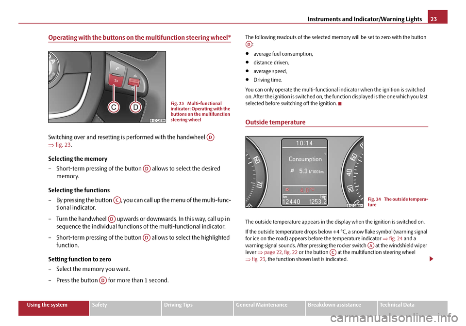
Operating with the buttons on the multifunction steering wheel*
Switching over and resetting is performed with the handwheel
⇒fig. 23 .
Selecting the memory
– Short-term pressing of the button allows to select the desired
memory.
Selecting the functions
– By pressing the button , you can call up the menu of the multi-func- tional indicator.
– Turn the handwheel upwards or downwards. In this way, call up in sequence the individual functions of the multi-functional indicator.
– Short-term pressing of the button allows to select the highlighted
function.
Setting function to zero
– Select the memory you want.
– Press the button for more than 1 second.
The following readouts of the selected memo ry will be set to zero with the button
:
•average fuel consumption,
•distance driven,
•average speed,
•Driving time.
You can only operate the multi-functional indicator when the ignition is switched
on. After the ignition is switched on, the fu nction displayed is the one which you last
selected before switching off the ignition.
Outside temperature
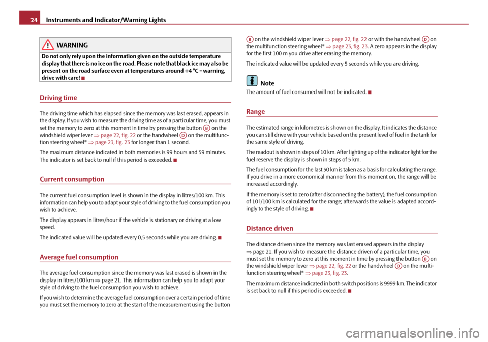
The outside temperature appears in the disp lay when the ignition is switched on.
If the outside temperature drops below +4 °C, a snow flake symbol (warning signal
for ice on the road) appears before the temperature indicator ⇒fig. 24 and a
warning signal sounds. After pressing the rocker switch at the windshield wiper
lever ⇒page 22, fig. 22 or the button at the multifunction steering wheel
⇒ fig. 23 , the function shown last is indicated.
Fig. 23 Multi-functional
indicator: Operating with the
buttons on the multifunction
steering wheel
AD
AD
AC
AD
AD
AD
AD
Fig. 24 The outside tempera-
ture
AAAC
20A5Facelift.book Page 23 Saturday, September 6, 2008 2:13 PM
Page 25 of 304
Instruments and Indicator/Warning Lights
24
WARNING
Do not only rely upon the information given on the outside temperature
display that there is no ice on the road. Please note that black ice may also be
present on the road surface even at te mperatures around +4 °C - warning,
drive with care!
Driving time
The driving time which has elapsed since the memory was last erased, appears in
the display. If you wish to measure the driving time as of a particular time, you must
set the memory to zero at this moment in time by pressing the button on the
windshield wiper lever ⇒page 22, fig. 22 or the handwheel on the multifunc-
tion steering wheel* ⇒page 23, fig. 23 for longer than 1 second.
The maximum distance indicated in both memories is 99 hours and 59 minutes.
The indicator is set back to nu ll if this period is exceeded.
Current consumption
The current fuel consumption level is shown in the display in litres/100 km. This
information can help you to adapt your style of driving to the fuel consumption you
wish to achieve.
The display appears in litres/hour if the vehicle is stationary or driving at a low
speed.
The indicated value will be updated every 0,5 seconds while you are driving.
Average fuel consumption
The average fuel consumption since the memory was last erased is shown in the
display in litres/100 km ⇒page 21. This information can help you to adapt your
style of driving to the fuel co nsumption you wish to achieve.
If you wish to determine the average fuel consumption over a certain period of time
you must set the memory to zero at the start of the measurement using the button on the windshield wiper lever
⇒page 22, fig. 22 or with the handwheel on
the multifunction steering wheel* ⇒page 23, fig. 23 . A zero appears in the display
for the first 100 m you drive after erasing the memory.
The indicated value will be updated every 5 seconds while you are driving.
Note
The amount of fuel consum ed will not be indicated.
Range
The estimated range in kilometres is shown on the display. It indicates the distance
you can still drive with your vehicle based on the present level of fuel in the tank for
the same style of driving.
The readout is shown in steps of 10 km. After lighting up of the indicator light for the
fuel reserve the display is shown in steps of 5 km.
The fuel consumption for the last 50 km is taken as a basis for calculating the range.
If you drive in a more economical manner from this moment on, the range will be
increased accordingly.
If the memory is set to zero (after disc onnecting the battery), the fuel consumption
of 10 l/100 km is calculated for the range; afterwards the value is adapted accord-
ingly to the style of driving.
Distance driven
The distance driven since the memory was last erased appears in the display
⇒ page 21. If you wish to measure the dist ance driven of a particular time, you
must set the memory to zero at this mome nt in time by pressing the button on
the windshield wiper lever ⇒page 22, fig. 22 or the handwheel on the multi-
function steering wheel* ⇒page 23, fig. 23 .
The maximum distance indicated in both switch positions is 9999 km. The indicator
is set back to null if this period is exceeded.
ABAD
ABAD
ABAD
20A5Facelift.book Page 24 Saturday, September 6, 2008 2:13 PM
Page 26 of 304
Instruments and Indicator/Warning Lights25
Using the systemSafetyDriving TipsGeneral MaintenanceBreakdown assistanceTechnical Data
Average speed
The average speed since the memory was last erased is shown in the display in
km/hour ⇒page 21. If you wish to determine the average vehicle speed over a
certain period of time you must set the me mory to zero at the start of the measure-
ment using the button on the windshield wiper lever ⇒page 22, fig. 22 or with
the handwheel on the mult ifunction steering wheel* ⇒page 23, fig. 23 .
A zero appears in the display for the first 100 m you drive after erasing the memory.
The indicated value will be updated every 5 seconds while you are driving.
Current speed*
The current speed which is identical to the display of the speedometer, is indicated
on the display ⇒page 17, fig. 18 .
Warning against excessive speeds*
Warning against excessive speeds
This function enables you to set a speed limit, e.g. if you drive in town. A text in the
display is intended to draw yo ur attention to the fact that you have exceeded the set
speed limit.
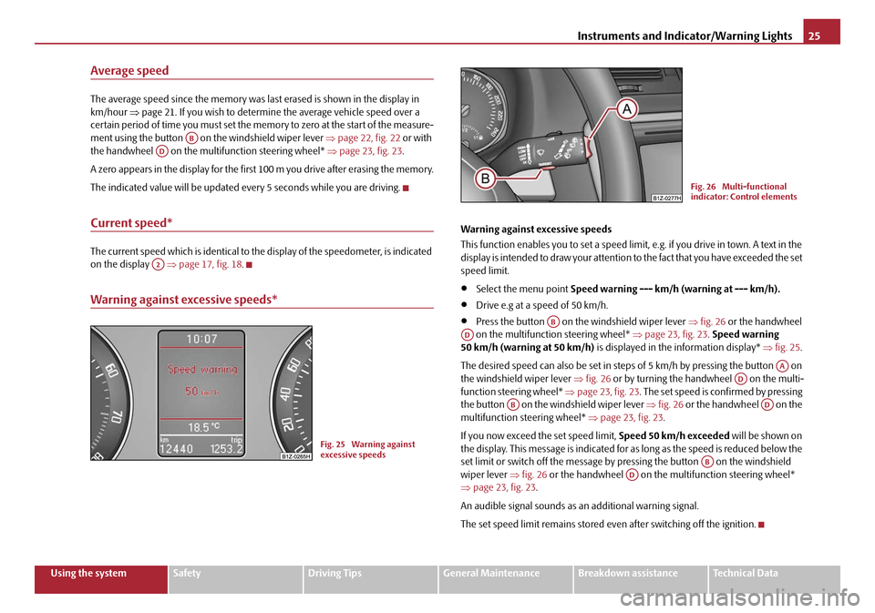
•Select the menu point Speed warning --- km/h (warning at --- km/h).
•Drive e.g at a speed of 50 km/h.
•Press the button on the windshield wiper lever ⇒fig. 26 or the handwheel
on the multifunction steering wheel* ⇒page 23, fig. 23 . Speed warning
50 km/h (warning at 50 km/h) is displayed in the information display* ⇒fig. 25 .
The desired speed can also be set in steps of 5 km/h by pressing the button on
the windshield wiper lever ⇒fig. 26 or by turning the handwheel on the multi-
function steering wheel* ⇒page 23, fig. 23 . The set speed is confirmed by pressing
the button on the windshield wiper lever ⇒fig. 26 or the handwheel on the
multifunction st eering wheel* ⇒page 23, fig. 23.
If you now exceed th e set speed limit, Speed 50 km/h exceeded will be shown on
the display. This message is indicated for as long as the speed is reduced below the
set limit or switch off the message by pr essing the button on the windshield
wiper lever ⇒fig. 26 or the handwheel on the multifunction steering wheel*
⇒ page 23, fig. 23 .
An audible signal sounds as an additional warning signal.
The set speed limit remains stored even after switching off the ignition.
ABAD
A2
Fig. 25 Warning against
excessive speeds
Fig. 26 Multi-functional
indicator: Control elements
ABAD
AAAD
ABAD
ABAD
20A5Facelift.book Page 25 Saturday, September 6, 2008 2:13 PM
Page 27 of 304
Instruments and Indicator/Warning Lights
26
Information display*
Introduction
The information display provides you with information in a convenient way
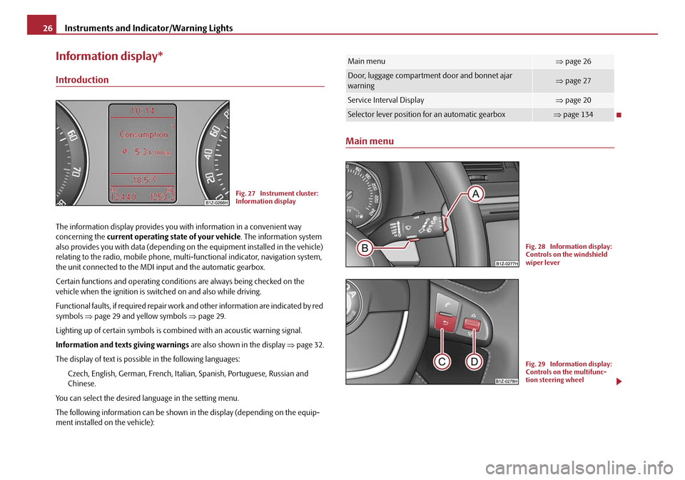
concerning the current operating state of your vehicle . The information system
also provides you with data (depending on the equipment installed in the vehicle)
relating to the radio, mobile phone, mult i-functional indicator, navigation system,
the unit connected to the MDI input and the automatic gearbox.
Certain functions and operating conditio ns are always being checked on the
vehicle when the ignition is switched on and also while driving.
Functional faults, if required repair work and other information are indicated by red
symbols ⇒page 29 and yellow symbols ⇒page 29.
Lighting up of certain symbols is comb ined with an acoustic warning signal.
Information and text s giving warnings are also shown in the display ⇒page 32.
The display of text is possible in the following languages: Czech, English, German, French, Italia n, Spanish, Portuguese, Russian and
Chinese.
You can select the desired language in the setting menu.
The following information can be shown in the display (depending on the equip-
ment installed on the vehicle):
Main menu
Fig. 27 Instrument cluster:
Information display
Main menu⇒ page 26
Door, luggage compartment door and bonnet ajar
warning⇒page 27
Service Interval Display⇒page 20
Selector lever position for an automatic gearbox⇒page 134
Fig. 28 Information display:
Controls on the windshield
wiper lever
Fig. 29 Information display:
Controls on the multifunc-
tion steering wheel
20A5Facelift.book Page 26 Saturday, September 6, 2008 2:13 PM