fuel pressure SKODA OCTAVIA 2009 2.G / (1Z) User Guide
[x] Cancel search | Manufacturer: SKODA, Model Year: 2009, Model line: OCTAVIA, Model: SKODA OCTAVIA 2009 2.G / (1Z)Pages: 304, PDF Size: 19.56 MB
Page 240 of 304

Wheels and Tyres
239
Using the system
Safety
Driving Tips
General Maintenance
Breakdown assistance
Technical Data
setting off on a long trip. Please do not
forget the spare wheel when checking the
tyres. The tyre inflation pressures for
summer tyres
are indicated on the inside of the fuel
filler flap
⇒page 238, fig. 218
. The inflation pressures for
winter tyres
are 20 kPa
(0.2 bar) higher than those for summer tyres
⇒page 242.
The tyre pressure should be at the highest pressure specified for your vehicle at all times. The tyre inflation pressure of the emergency spare wheel R 18 is 420 kPa (4.2 bar).Always check the inflation pressure of ty
res when cold. Do not reduce the higher
pressure of warm tyres. Adapt the inflation pressure of the tyres accordingly if your vehicle is carrying a significantly higher payload. Driving style Fast cornering, sharp acceleration and braking (squealing tyres) increase wear-and- tear on your tyres. Balancing wheels The wheels of a new vehicle are balanced. There are a wide range of influences when driving which may result in an im
balance and which makes themselves felt
through vibration in the steering. You should have the wheels rebalanced since any imbalance increases wear-and- tear on the steering, the suspension and tyres. A wheel must also be rebalanced when a new tyre is fitted and each time a tyre is repaired. Wheel alignment errors Incorrect wheel alignment at the front and rear will not only increase wear-and-tear on the tyres but will also has an adverse effect on vehicle safety. Contact your specialist garage if you no
tice any unusual tyre wear.
WARNING
•
If the inflation pressure is too low,
the tyre must perform a greater flexing
work. At higher speeds the tyre will warm up as a result of this. This can result in tread separation and even a tyre blowout.•
Immediately replace the damaged rims or tyres.
•
Tyres which are 6 years old or more should only be fitted in exceptional
cases and when adopting an appropriately cautious style of driving.
For the sake of the environment
Tyres which are insufficiently inflated increase your fuel consumption.Wear indicatorsThe base of the tread of the original tyres has wear indicators 1.6 mm high, installed at right angles to the direction of travel. These wear indicators are located at 6 - 8 points depending on the make and are evenly spaced around the circumference of the tyre
⇒fig. 219
. Markings on the walls of the tyres through the letters “TWI”,
triangular symbols or other symbols identi
fy the position of the wear indicators.
A remaining tread of just 1.6 mm, measured in the grooves of the tread next to the wear indicators, means that your tyres have reached their legally permissible minimum tread depth.
WARNING (continued)
Fig. 219 Tyre tread with wear indicators
se0.1.book Page 239 Frida
y, April 10, 2009 3:19 PM
Page 248 of 304

Breakdown assistance
247
Using the system
Safety
Driving Tips
General Maintenance
Breakdown assistance
Technical Data
repair can be undertaken on
the vehicle immediately.
Please read the attached
instructions carefully before the repair. The tyre repair kit is located in a textile ba
g. There is a velcro fastener on the under-
side of the bag, with which the bag is atta
ched to the floor covering of the luggage
compartment in such a way that the side of the bag rests on the right side of the luggage compartment and on the seat backrest.Spare wheel*The spare wheel lies in a well under the floor covering of the luggage compartment and is fixed in place using special screws
⇒fig. 224
.
Before removing the spare wheel, you must take out the box with the vehicle tool kit box
⇒page 246, fig. 223
.
One should check the inflation pressure in the spare wheel (at best when generally checking the tyre air pressures - see sign on the fuel filler flap
⇒page 238) to
ensure that the spare wheel is always ready to use. Temporary spare wheel A warning label displayed on the rim of the temporary spare wheel indicates that your vehicle is equipped with a temporary spare wheel. Please observe the following notes when driving with a temporary spare wheel:
•
After fitting on the wheel, the warning st
icker must not be concealed (e.g. by the
wheel trim).•
D o n o t d r i v e w i t h th i s s p a re w h e e l a t m o re th a n 8 0 k m / h - ri s k o f a c c i d e n t. Av o i d
accelerating at full throttle, sharp braking and fast cornering.•
The inflation pressure for this spare wheel is identical to the inflation pressure
of the standard tyres. The temporary spar
e wheel R 18 must have an inflation pres-
sure of 420 kPa (4.2 bar)!•
Use this spare wheel only to reach the nearest specialist garage as it is not
intended for continuous use.•
No other summer or winter tyres must
be mounted on the rim of the spare
wheel R 18.Changing a wheelPreliminary workThe following steps should be carried out before actually changing the wheel. – If it is necessary to change a wheel, park the vehicle as far away as
possible from the traffic flow. The place you choose should be
level
.
–Have
all the occupants get out.
While changing a wheel, the occu-
pants of the vehicle should not stan
d on the road (e.g. behind a crash
barrier).
– Apply the
handbrake
firmly.
–Engage
1st gear
or if your vehicle is fitted with an automatic gearbox,
position the
selector lever into position P
.
– If a trailer is coupled, uncouple it.– Take the
vehicle tool kit
⇒
page 246 and the
spare wheel*
⇒
page 247 out of the luggage compartment.
Fig. 224 Luggage compart- ment: Spare wheel
se0.1.book Page 247 Frida
y, April 10, 2009 3:19 PM
Page 261 of 304
Fuses and light bulbs
260
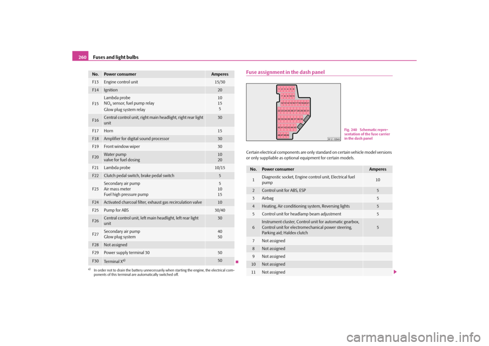
Fuse assignment in the dash panelCertain electrical components are only standard on certain vehicle model versions or only suppliable as optional
equipment for certain models.
F13
Engine control unit
15/30
F14
Ignition
20
F15
Lambda probe NO
x sensor, fuel pump relay
Glow plug system relay
10 15 5
F16
Central control unit, right main headlight, right rear light unit
30
F17
Horn
15
F18
Amplifier for digital sound processor
30
F19
Front window wiper
30
F20
Water pumpvalve for fuel dosing
1020
F21
Lambda probe
10/15
F22
Clutch pedal switch, brake pedal switch
5
F23
Secondary air pump Air mass meter Fuel high pressure pump
5 10 15
F24
Activated charcoal filter, ex
haust gas recirculation valve
10
F25
Pump for ABS
30/40
F26
Central control unit, left main headlight, left rear light unit
30
F27
Secondary air pump Glow plug system
4050
F28
Not assigned
F29
Power supply terminal 30
50
F30
Te r m i n a l X
a)
50
a)In order not to drain the battery unnecessarily
when starting the engine, the electrical com-
ponents of this terminal are automatically switched off.No.
Power consumer
Amperes
No.
Power consumer
Amperes
1
Diagnostic socket, Engine co
ntrol unit, Electrical fuel
pump
10
2
Control unit for ABS, ESP
5
3
Airbag
5
4
Heating, Air conditioning system, Reversing lights
5
5
Control unit for headla
mp beam adjustment
5
6
Instrument cluster, Control unit for automatic gearbox, Control unit for electromec
hanical power steering,
Parking aid; Haldex clutch
5
7
Not assigned
8
Not assigned
9
Not assigned
10
Not assigned
11
Not assigned
Fig. 240 Schematic repre- sentation of the fuse carrier in the dash panel
se0.1.book Page 260 Frida
y, April 10, 2009 3:19 PM
Page 273 of 304

Technical Data
272
Identification detailsVehicle data sticker The vehicle data sticker
⇒fig. 256
is located on the floor of the luggage compart-
ment and is also stated in the Service schedule. The vehicle data sticker co
ntains the following data:
Vehicle identification number (VIN) Vehicle type Gearbox code, paint number, interior
equipment number, engine output,
engine code Partial description of the vehicle 7GG, 7MB, 7MG - vehicles with DPF
⇒page 200
Vehicle identification number (VIN) The vehicle identification num
ber - VIN (vehicle body number) is stamped into the
engine compartment on the right hand shoc
k absorber dome. This number is also
located on a sign on the lower left hand edge below the windscreen. Engine number The engine number is stamped into the engine block. Type plate (production plate) The type plate is located in the lower area of the left centre column.
Homologation sign The homologation sign is located on the in
side of the bonnet next to the lock. Vehi-
cles for certain countries do no
t have an homologation sign.
Sticker on inside of fuel filler flap The stickers are affixed to the inside of the fuel filler flap and contain the following information:•
The prescribed types of fuel,
•
Tyre s iz e ,
•
Tyre pressure.
Fuel consumption according to the regulations (99/100/EU)Depending on the range of the special equipment, style of driving, traffic situation, weather influences and vehi
cle condition, the consumpt
ion values which in prac-
tice result when using the vehicle ca
n deviate from the indicated values.
Urban traffic The consumption measurement in urban traf
fic begins with starting of the cold
engine. Afterwards the normal
urban traffic is simulated.
Non-urban traffic For the consumption measurement in non-ur
ban traffic the vehicle, as in daily
motoring, is accelerated and braked several times in all gears. The vehicle speed changes within the range from 0 to 120 km/h. Combined traffic The consumption value in the combined traf
fic consists of 37%
from the value for
the urban traffic and of 63% from
the value for the non-urban traffic.
Fig. 256 Vehicle data sticker
A1A2A3A4A5se0.1.book Page 272 Frida
y, April 10, 2009 3:19 PM