fuel consumption SKODA OCTAVIA 2009 2.G / (1Z) Owner's Manual
[x] Cancel search | Manufacturer: SKODA, Model Year: 2009, Model line: OCTAVIA, Model: SKODA OCTAVIA 2009 2.G / (1Z)Pages: 304, PDF Size: 19.56 MB
Page 1 of 304

SIMPLY CLEVER
ŠkodaOctavia
OWNER'S MANUAL
How you can contribute to a cleaner environment
The fuel consumption of your Škoda - and thus the level of pollutants contained
in the exhaust - is also determined by how you drive.
The noise level and wear and tear are also influenced by how you personally
handle your vehicle. This Owner's Manual tells you how to drive your Škoda to
achieve the minimum impact on the environment, and how to save money at
the same time. Look up „Environment“ in the Index to find out more.
Please also refer to all the texts identified with a
in this Owner's Manual.
Make your contribution - for the sake of the environment.
www.skoda-auto.com
Návod k obsluze
Octavia anglicky 05.09
S64.5610.06.20
1Z0 012 003 JD
Octavia anglicky 05.09 S64.5610.06.20
Page 5 of 304
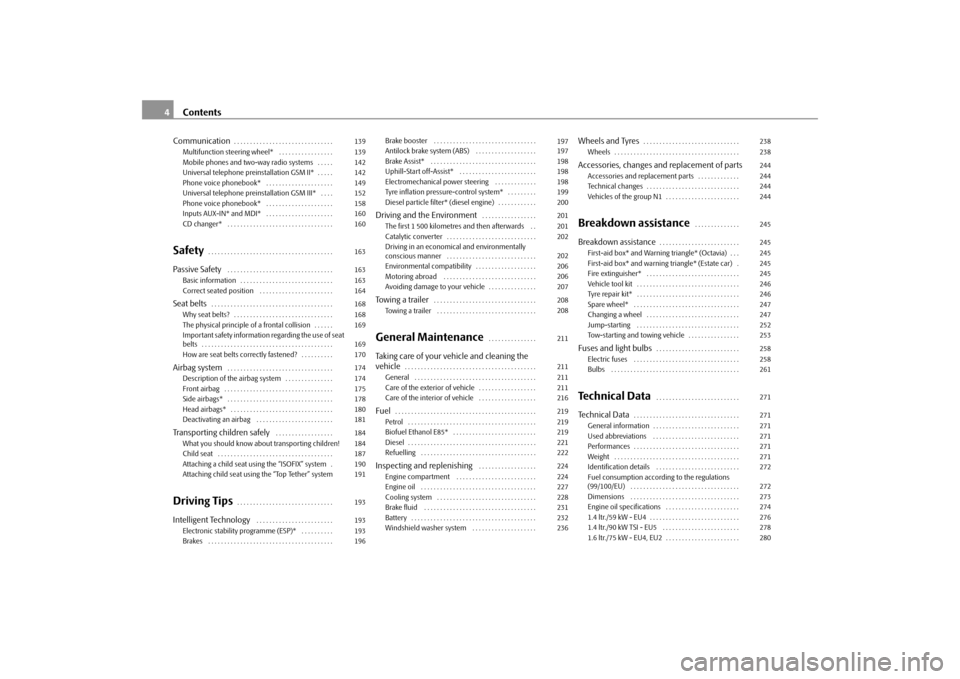
Contents 4Communication
. . . . . . . . . . . . . . . . . . . . . . . . . . . . . . .
Multifunction steering wheel* . . . . . . . . . . . . . . . . .
Mobile phones and two-way radio systems . . . . .
Universal telephone preinstallation GSM II* . . . . .
Phone voice phonebook* . . . . . . . . . . . . . . . . . . . . .
Universal telephone preinstallation GSM III* . . . .
Phone voice phonebook* . . . . . . . . . . . . . . . . . . . . .
Inputs AUX-IN* and MDI* . . . . . . . . . . . . . . . . . . . . .
CD changer* . . . . . . . . . . . . . . . . . . . . . . . . . . . . . . . . .
Safety
. . . . . . . . . . . . . . . . . . . . . . . . . . . . . . . . . . . . . . .
Passive Safety
. . . . . . . . . . . . . . . . . . . . . . . . . . . . . . . . .
Basic information . . . . . . . . . . . . . . . . . . . . . . . . . . . . .
Correct seated position . . . . . . . . . . . . . . . . . . . . . . .
Seat belts
. . . . . . . . . . . . . . . . . . . . . . . . . . . . . . . . . . . . . .
Why seat belts? . . . . . . . . . . . . . . . . . . . . . . . . . . . . . . .
The physical principle of a frontal collision . . . . . .
Important safety information regarding the use of seat
belts . . . . . . . . . . . . . . . . . . . . . . . . . . . . . . . . . . . . . . . . .
How are seat belts correctly fastened? . . . . . . . . . .
Airbag system
. . . . . . . . . . . . . . . . . . . . . . . . . . . . . . . . .
Description of the airbag system . . . . . . . . . . . . . . .
Front airbag . . . . . . . . . . . . . . . . . . . . . . . . . . . . . . . . . .
Side airbags* . . . . . . . . . . . . . . . . . . . . . . . . . . . . . . . . .
Head airbags* . . . . . . . . . . . . . . . . . . . . . . . . . . . . . . . .
Deactivating an airbag . . . . . . . . . . . . . . . . . . . . . . . .
Transporting children safely
. . . . . . . . . . . . . . . . . .
What you should know about transporting children!
Child seat . . . . . . . . . . . . . . . . . . . . . . . . . . . . . . . . . . . .
Attaching a child seat using the “ISOFIX” system .
Attaching child seat using the “Top Tether” system
Driving Tips
. . . . . . . . . . . . . . . . . . . . . . . . . . . . . .
Intelligent Technology
. . . . . . . . . . . . . . . . . . . . . . . .
Electronic stability programme (ESP)* . . . . . . . . . .
Brakes . . . . . . . . . . . . . . . . . . . . . . . . . . . . . . . . . . . . . . . Brake booster . . . . . . . . . . . . . . . . . . . . . . . . . . . . . . . .
Antilock brake system (ABS) . . . . . . . . . . . . . . . . . . .
Brake Assist* . . . . . . . . . . . . . . . . . . . . . . . . . . . . . . . . .
Uphill-Start off-Assist* . . . . . . . . . . . . . . . . . . . . . . . .
Electromechanical power steering . . . . . . . . . . . . .
Tyre inflation pressure-control system* . . . . . . . . .
Diesel particle filter* (diesel engine) . . . . . . . . . . . .
Driving and the Environment
. . . . . . . . . . . . . . . . .
The first 1 500 kilometres and then afterwards . .
Catalytic converter . . . . . . . . . . . . . . . . . . . . . . . . . . . .
Driving in an economical and environmentally
conscious manner . . . . . . . . . . . . . . . . . . . . . . . . . . . .
Environmental compatibility . . . . . . . . . . . . . . . . . . .
Motoring abroad . . . . . . . . . . . . . . . . . . . . . . . . . . . . .
Avoiding damage to your vehicle . . . . . . . . . . . . . . .
Towing a trailer
. . . . . . . . . . . . . . . . . . . . . . . . . . . . . . . .
Towing a trailer . . . . . . . . . . . . . . . . . . . . . . . . . . . . . . .
General Maintenance
. . . . . . . . . . . . . . .
Taking care of your vehicle and cleaning the
vehicle
. . . . . . . . . . . . . . . . . . . . . . . . . . . . . . . . . . . . . . . . .
General . . . . . . . . . . . . . . . . . . . . . . . . . . . . . . . . . . . . . .
Care of the exterior of vehicle . . . . . . . . . . . . . . . . . .
Care of the interior of vehicle . . . . . . . . . . . . . . . . . .
Fuel
. . . . . . . . . . . . . . . . . . . . . . . . . . . . . . . . . . . . . . . . . . . .
Petrol . . . . . . . . . . . . . . . . . . . . . . . . . . . . . . . . . . . . . . . .
Biofuel Ethanol E85* . . . . . . . . . . . . . . . . . . . . . . . . . .
Diesel . . . . . . . . . . . . . . . . . . . . . . . . . . . . . . . . . . . . . . . .
Refuelling . . . . . . . . . . . . . . . . . . . . . . . . . . . . . . . . . . . .
Inspecting and replenishing
. . . . . . . . . . . . . . . . . .
Engine compartment . . . . . . . . . . . . . . . . . . . . . . . . .
Engine oil . . . . . . . . . . . . . . . . . . . . . . . . . . . . . . . . . . . .
Cooling system . . . . . . . . . . . . . . . . . . . . . . . . . . . . . . .
Brake fluid . . . . . . . . . . . . . . . . . . . . . . . . . . . . . . . . . . .
Battery . . . . . . . . . . . . . . . . . . . . . . . . . . . . . . . . . . . . . . .
Windshield washer system . . . . . . . . . . . . . . . . . . . .
Wheels and Tyres
. . . . . . . . . . . . . . . . . . . . . . . . . . . . . .
Wheels . . . . . . . . . . . . . . . . . . . . . . . . . . . . . . . . . . . . . . .
Accessories, changes and replacement of partsAccessories and replacement parts . . . . . . . . . . . . .
Technical changes . . . . . . . . . . . . . . . . . . . . . . . . . . . . .
Vehicles of the group N1 . . . . . . . . . . . . . . . . . . . . . . .Breakdown assistance
. . . . . . . . . . . . . .
Breakdown assistance
. . . . . . . . . . . . . . . . . . . . . . . . .
First-aid box* and Warning triangle* (Octavia) . . .
First-aid box* and warning triangle* (Estate car) .
Fire extinguisher* . . . . . . . . . . . . . . . . . . . . . . . . . . . . .
Vehicle tool kit . . . . . . . . . . . . . . . . . . . . . . . . . . . . . . . .
Tyre repair kit* . . . . . . . . . . . . . . . . . . . . . . . . . . . . . . . .
Spare wheel* . . . . . . . . . . . . . . . . . . . . . . . . . . . . . . . . .
Changing a wheel . . . . . . . . . . . . . . . . . . . . . . . . . . . . .
Jump-starting . . . . . . . . . . . . . . . . . . . . . . . . . . . . . . . .
Tow-starting and towing vehicle . . . . . . . . . . . . . . . .
Fuses and light bulbs
. . . . . . . . . . . . . . . . . . . . . . . . . .
Electric fuses . . . . . . . . . . . . . . . . . . . . . . . . . . . . . . . . .
Bulbs . . . . . . . . . . . . . . . . . . . . . . . . . . . . . . . . . . . . . . . .
Technical Data
. . . . . . . . . . . . . . . . . . . . . . . . . .
Technical Data
. . . . . . . . . . . . . . . . . . . . . . . . . . . . . . . . .
General information . . . . . . . . . . . . . . . . . . . . . . . . . . .
Used abbreviations . . . . . . . . . . . . . . . . . . . . . . . . . . .
Performances . . . . . . . . . . . . . . . . . . . . . . . . . . . . . . . . .
Weight . . . . . . . . . . . . . . . . . . . . . . . . . . . . . . . . . . . . . . .
Identification details . . . . . . . . . . . . . . . . . . . . . . . . . .
Fuel consumption according to the regulations
(99/100/EU) . . . . . . . . . . . . . . . . . . . . . . . . . . . . . . . . . .
Dimensions . . . . . . . . . . . . . . . . . . . . . . . . . . . . . . . . . .
Engine oil specifications . . . . . . . . . . . . . . . . . . . . . . .
1.4 ltr./59 kW - EU4 . . . . . . . . . . . . . . . . . . . . . . . . . . . .
1.4 ltr./90 kW TSI - EU5 . . . . . . . . . . . . . . . . . . . . . . . .
1.6 ltr./75 kW - EU4, EU2 . . . . . . . . . . . . . . . . . . . . . . . 139
139
142
142
149
152
158
160
160
163
163
163
164
168
168
169
169
170
174
174
175
178
180
181
184
184
187
190
191
193
193
193
196197
197
198
198
198
199
200
201
201
202
202
206
206
207
208
208
211
211
211
211
216
219
219
219
221
222
224
224
227
228
231
232
236238
238
244
244
244
244
245
245
245
245
245
246
246
247
247
252
253
258
258
261
271
271
271
271
271
271
272
272
273
274
276
278
280
se0.1.book Page 4 Friday, April 10, 2009 3:19 PM
Page 22 of 304
Instruments and Indicator/Warning Lights
21
Using the system
Safety
Driving Tips
General Maintenance
Breakdown assistance
Technical Data
Digital clockYou can set the time with the rotary knob
⇒page 17, fig. 18
.
Select the information which you wish to change by turning the button and carry out the change of the selected information by pressing the button. On vehicles which are fitted out with the information display*, it is possible to set the time in the menu
Time
⇒page 29.
WARNING
The clock should not be adjusted while driving for safety reasons but only when the vehicle is stationary!Multi-functional indicator (onboard computer)*IntroductionThe multi-functional indica
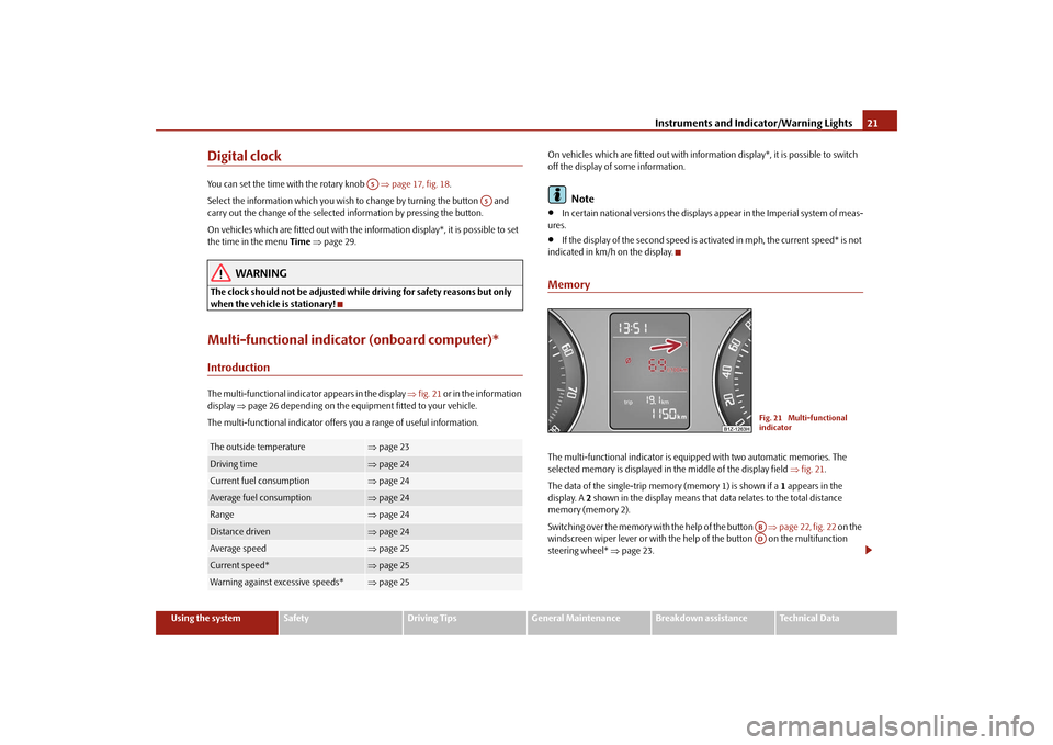
tor appears in the display
⇒fig. 21
or in the information
display
⇒page 26 depending on the equipment fitted to your vehicle.
The multi-functional indicator offers
you a range of useful information.
On vehicles which are fitted out with inform
ation display*, it is possible to switch
off the display of some information.
Note
•
In certain national versions
the displays appear in the Imperial system of meas-
ures.•
If the display of the second speed is acti
vated in mph, the current speed* is not
indicated in km/h on the display.MemoryThe multi-functional indicator is equi
pped with two automatic memories. The
selected memory is displayed in the middle of the display field
⇒fig. 21
.
The data of the single-trip memo
ry (memory 1) is shown if a
1 appears in the
display. A
2 shown in the display means that da
ta relates to the total distance
memory (memory 2). Switching over the memory with the help of the button
⇒page 22, fig. 22
on the
windscreen wiper lever or with the help
of the button on the multifunction
steering wheel*
⇒page 23.
The outside temperature
⇒page 23
Driving time
⇒page 24
Current fuel consumption
⇒page 24
Average fuel consumption
⇒page 24
Range
⇒page 24
Distance driven
⇒page 24
Average speed
⇒page 25
Current speed*
⇒page 25
Warning against excessive speeds*
⇒page 25A5
A5
Fig. 21 Multi-functional indicatorABAD
se0.1.book Page 21 Friday, April 10, 2009 3:19 PM
Page 23 of 304
Instruments and Indicator/Warning Lights
22
Single-trip memory (memory 1) The single-trip memory collates the driving information from the moment the igni- tion is switched on until it
is switched off. New data will
also flow into the calcula-
tion of the current driving information if the trip is continued
within 2 hours
after
switching off the ignition. The memory will
be is automatically erased, on the other
hand, if the trip is interrupted for
more than 2 hours
.
Total-trip memory (memory 2) The total distance driven memory gathers
data from any number of individual jour-
neys up to a total of 99 hours and 59 minutes driving or 9.999 kilometres driven. The memory is deleted when either of these limits is reached and the calculation starts from anew. The total-trip memory will not, contrary
to the single-trip memory, be deleted after
a period of interruption
of driving of 2 hours.
Note
All information in the memory
1 and
2 is erased if the battery of the vehicle is
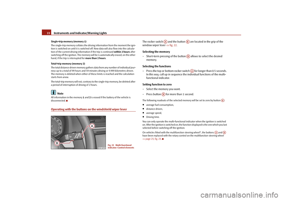
disconnected.Operating with the buttons on the windshield wiper lever
The rocker switch and the button are located in the grip of the window wiper lever
⇒
fig. 22
.
Selecting the memory – Short-term pressing of the button
allows to select the desired
memory.
Selecting the functions – Press the top or bottom rocker switch for longer than 0.5 seconds.
In this way, call up in sequence the individual functions of the multi-functional indicator.
Setting function to zero – Select the memory you want. – Press button for more than 1 second.The following readouts of the selected memory will be set to zero by button :•
average fuel consumption,
•
distance driven,
•
average speed,
•
Driving time.
You can only operate the multi-functional
indicator when the ignition is switched
on. After the ignition is switched on, the fu
nction displayed is the one which you last
selected before switching off the ignition. On vehicles fitted with the multifunction steering wheel*, the buttons and have been replaced with the rotary cont
rol on the multifunction steering wheel
⇒ page 23, fig. 23
.
Fig. 22 Multi-functional indicator: Control elements
AA
ABABAA
AB
AB
AA
AB
se0.1.book Page 22 Friday, April 10, 2009 3:19 PM
Page 24 of 304

Instruments and Indicator/Warning Lights
23
Using the system
Safety
Driving Tips
General Maintenance
Breakdown assistance
Technical Data
Operating with the buttons on the multifunction steering wheel*Switching over and resetting is performed with the handwheel ⇒
fig. 23
.
Selecting the memory – Short-term pressing of the button
allows to select the desired
memory.
Selecting the functions – By pressing the button , you can call up the menu of the multi-func-
tional indicator.
– Turn the handwheel upwards or downwards. In this way, call up in
sequence the individual functions of the multi-functional indicator.
– Short-term pressing of the button
allows to select the highlighted
function.
Setting function to zero – Select the memory you want. – Press the button for more than 1 second.
The following readouts of the selected memo
ry will be set to zero with the button
:•
average fuel consumption,
•
distance driven,
•
average speed,
•
Driving time.
You can only operate the multi-functional
indicator when the ignition is switched
on. After the ignition is switched on, the f
unction displayed is the one which you last
selected before switching off the ignition.Outside temperatureThe outside temperature appears in the disp
lay when the ignition is switched on.
If the outside temperature drops below +4 °C
, a snow flake symbol (warning signal
for ice on the road) appears before the temperature indicator
⇒fig. 24
and a
warning signal sounds. After pressing the rocker switch at the windshield wiper lever
⇒page 22, fig. 22
or the button at the multifunction steering wheel
⇒ fig. 23
, the function shown last is indicated.
Fig. 23 Multi-functional indicator: Operating with the buttons on the multifunction steering wheel
AD
AD
AC
AD
AD
AD
AD
Fig. 24 The outside tempera-tureAA
AC
se0.1.book Page 23 Friday, April 10, 2009 3:19 PM
Page 25 of 304
Instruments and Indicator/Warning Lights
24
WARNING
Do not only rely upon the information given on the outside temperature display that there is no ice on the road.
Please note that black ice may also be
present on the road surface even at
temperatures around +4°C - warning,
drive with care!Driving timeThe driving time which has elapsed since the memory was last erased, appears in the display. If you wish to
measure the driving time as of a particular time, you must
set the memory to zero at this moment in
time by pressing the button on the
windshield wiper lever
⇒page 22, fig. 22
or the handwheel on the multifunc-
tion steering wheel*
⇒page 23, fig. 23
for longer than 1 second.
The maximum distance indicated in both memories is 99 hours and 59 minutes. The indicator is set back to nu
ll if this period is exceeded.
Current consumptionThe current fuel consumption level is shown in the display in litres/100 km. This information can help you to
adapt your style of driving to the fuel consumption you
wish to achieve. The display appears in litres/hour if the vehicle is stationary or driving at a low speed. The indicated value will be updated every 0.5 seconds while you are driving.Average fuel consumptionThe average fuel consumption since the memory was last erased is shown in the display in litres/100 km
⇒page 21. This information can help you to adapt your
style of driving to the fuel co
nsumption you wish to achieve.
If you wish to determine the average fuel
consumption over a cert
ain period of time
you must set the memory to zero at the start of the measurement using the button
on the windshield wiper lever
⇒page 22, fig. 22
or with the handwheel on
the multifunction steering wheel*
⇒page 23, fig. 23
. A zero appears in the display
for the first 100 m you drive after erasing the memory. The indicated value will be updated every 5 seconds while you are driving.
Note
The amount of fuel consum
ed will not be indicated.
RangeThe estimated range in kilometres is shown on the display. It indicates the distance you can still drive with your vehicle based on the present level of fuel in the tank for the same style of driving. The readout is shown in steps of 10 km. After lighting up of the indicator light for the fuel reserve the display is shown in steps of 5 km. The fuel consumption for the last 50 km is
taken as a basis for calculating the range.
If you drive in a more economical manner
from this moment on, the range will be
increased accordingly. If the memory is set to zero (after disc
onnecting the battery), the fuel consumption
of 10 ltr./100 km is calculated for the rang
e; afterwards the value is adapted accord-
ingly to the style of driving.Distance drivenThe distance driven since the memory was last erased appears in the display ⇒ page 21. If you wish to measure the dist
ance driven of a particular time, you
must set the memory to zero at this mome
nt in time by pressing the button on
the windshield wiper lever
⇒page 22, fig. 22
or the handwheel on the multi-
function steering wheel*
⇒page 23, fig. 23
.
The maximum distance indicated in both sw
itch positions is 9 999 km. The indicator
is set back to null if th
is period is exceeded.
AB
AD
AB
ADAB
AD
se0.1.book Page 24 Friday, April 10, 2009 3:19 PM
Page 35 of 304
Instruments and Indicator/Warning Lights
34
Diesel particle filter*
(diesel engine)
If the warning light
comes on, this means that soot has accumulated in the
diesel particle filter because of the frequent short distances. In order to clean the diesel particle filter,
the vehicle should be
driven at an even
speed of at least 60 km/h at engine speeds of 1 800 - 2 500 rpm for at least 15 minutes or until the warning light goes ou
t with the 4th or 5th gear engaged (auto-
matic gearbox: position S) when the traffi
c situation permits it. This increases the
exhaust temperature and the soot deposited in the diesel particle filter is burnt. Always pay attention to the valid speed limits
⇒
.
The warning light
goes out after the successful cleaning of the diesel particle
filter. If the filter is not properly
cleaned, the warning light
does not go out and the
warning light
begins to flash. In the information display* appears
Diesel-
particle Owner's manual
. Afterwards the engine control unit shifts the engine into
the emergency mode, which only has a reduced power output. After switching the ignition off and on again the warning light
comes on.
Have the vehicle inspected without delay by your specialist garage.
WARNING
•
If you do not pay attention to the warning light coming on and the corre-
sponding descriptions and warning notes, this may result in injuries or major vehicle damage.•
Always adjust your speed to suit weather, road, region and traffic condi-
tions. The route indicated by the warning light must not tempt you to disre- gard the national regulations for road traffic.
Caution
As long as the warning light
lights up, one must take into account an increased
fuel consumption and in certain circumst
ances a power reduction of the engine.
Note
Further information about diesel particle filter
⇒page 200.
Airbag system
Monitoring the airbag system The warning light
comes on for a few seconds when the ignition is switched on.
There is a fault in the system if the warning light does not go out or flashes while driving
⇒
. This also applies if the warning light does not come on when the igni-
tion is switched on. The following text will be displayed in the information display*:
Airbag fault!
The functionality of the airbag system is
also monitored electronically, when one
airbag has been switched off Front, side and head airbags or belt
tensioner which have been switched off
using the vehicle system tester:•
The warning light
lights up for 4 seconds after switching on the ignition and
then flashes again for 12 seconds in intervals of 2 seconds. The following text will be displayed in the information display*:
Airbag/belt tensio
ner deactivated!
Front passenger airbags switched off
using the switch for front passenger
airbags* in storage compartment on the front passenger side:•
the warning light
comes on for 4 seconds after the ignition has been
switched on,•
switching off the airbag is indicated in
the middle of the dash panel by the
lighting up of the indicator light
(airbag switched off)
⇒page 182.
se0.1.book Page 34 Friday, April 10, 2009 3:19 PM
Page 68 of 304

Lights and Visibility
67
Using the system
Safety
Driving Tips
General Maintenance
Breakdown assistance
Technical Data
If a door, the bonnet or the boot lid re
mains open, the light goes out within 2
minutes if the ignition is switched off.
WARNING
If the entry light comes on, do not touch its cover - risk of burns!VisibilityRear window heater– You can switch the rear window heater on or off by pressing the switch
⇒
fig. 63
- the indicator light in the
switch comes on or goes out.
The rear window heater only oper
ates when the engine is running.
The rear window heater
switches
off automatically after 10 minutes.
For the sake of the environment
As soon as the window is de-iced or free from mist, the heating should be switched off. The reduced current consumption will have a favourable effect on fuel economy
⇒page 205, “Saving electricity”.
Note
•
The position and the shape of the switch can differ depending on equipment
installed in the vehicle.•
If the on-board voltage drops, the rear
window heater
is switched off automat-
ically, in order to provide sufficient electrical energy for the engine control.Sun visorsYou can pull the sun visor for the driver or
front passenger out of the fixture and
swivel it toward the door in the direction of the arrow
⇒fig. 64
.
Fig. 63 Switch for rear window heater
Fig. 64 Sun visor: swivelling outFig. 65 Double sun visorA1
se0.1.book Page 67 Friday, April 10, 2009 3:19 PM
Page 95 of 304

Seats and Stowage
94
For the sake of the environment
The increased aerodynamic drag results in
a higher fuel consumption. One should
therefore take off the roof bar system after use.
Note
A roof rail is obtainable from a specialist garage if hasn't been fitted onto an estate car at the works, which carries
out the professional fitting.
Lashing points (Octavia)Perform the assembly and the disassembly
according to the attached instructions.
Note
•
If you have any questions, plea
se contact a specialist garage.
•
The figure is not valid for an estate car.
Roof loadDistribute weight evenly over the roof luggage rack system. The maximum permis- sible roof load (including roof rack system) of
75 kg
and the maximum permissible
total weight of the vehicle should not be exceeded. You cannot make full use of the permissible r
oof load if you use a roof luggage rack
system with a lower load carrying capa
city. The load transported on the roof
luggage rack system must not exceed the weight limit which is stated in the fitting instructions.
WARNING
•
The items which you transport on the roof bar system must be reliably
attached - risk of accident!•
You must on no account exceed the permissible roof load, the permis-
sible axle loads and the permissible gros
s weight of your vehicle - risk of
accident!•
Please note that the handling prop
erties of your ve
hicle change when
you transport heavy or bulky items on the roof bar system as a result of the displacement of the centre of gravity and the increased wind attack area - risk of accident! You must absolutely adapt your style of driving and the speed of the vehicle to the specific circumstances.
Fig. 108 Attachment points for base roof carrier
se0.1.book Page 94 Friday, April 10, 2009 3:19 PM
Page 115 of 304

Heating and air conditioning system
114
Recirculated air mode In recirculated air mode air is sucked
out of the interior of the vehicle
and then fed back into the interior.Recirculated air mode prevents polluted air outside the vehicle from getting into the vehicle, for example when driving through a tunnel or when standing in a traffic jam. Switching recirculated air mode on – Press the button
⇒
page 112, fig. 140
the warning light lights
up in the button.
Switching recirculated air mode off – Press again the button - the warning light in the button goes out.The recirculated air mode is switched off au
tomatically if the air distribution control
is in position
⇒page 112, fig. 140
. You can also switch recirculated air mode
on again from this setting by
repeatedly pressing button .
WARNING
You should not leave recirculated air mode on over a longer period of time, as “stale” air may result in fatigue in the driver and occupants, divert your attention and also cause the windows to mist up. The risk of having an acci-dent increases. Switch recirculated air mode off as soon as the windows begin misting up.Using the air conditioning system economicallyThe compressor on the air co
nditioning system uses po
wer from the engine when
in cooling mode which will effect the fuel consumption. It recommended to open the windows or the doors of a vehicle for which the inte- rior has been strongly heated through the ef
fect of direct sunlight in order to allow
the heated air to escape. The cooling system should not be switched on while travelling when the window is open. The desired interior temperature can also be achieved without switching in the cooling system just by switching to fresh air mode.
comfortable heating
desired tempera-
ture
2 or 3
switched off
do not switch on
open
the fastest cooling
recommended
22°C
briefly 4, then
2or 3
switched on
briefly switched on
open
optimal cooling
desired tempera-
ture
1, 2 or 3
switched on
do not switch on
open and align to the roof
Fresh air mode - ventilation
up to the stop towards the left
desired position
switched off
do not switch on
open
Set-up
Setting of the control dial
Button
Air outlet vents 3
AA
AB
AC
A1
A4
A4
AC
se0.1.book Page 114 Frida
y, April 10, 2009 3:19 PM