battery SKODA OCTAVIA 2009 2.G / (1Z) Owner's Guide
[x] Cancel search | Manufacturer: SKODA, Model Year: 2009, Model line: OCTAVIA, Model: SKODA OCTAVIA 2009 2.G / (1Z)Pages: 304, PDF Size: 19.56 MB
Page 227 of 304

Inspecting and replenishing
226
ribbed belt, alternator, radiator fan) and from the high-voltage ignition system. Please observe in addition the following:
− Never touch the electrical cabl
es of the ignition system.
− Absolutely avoid any jewellery, loose items of clothing or long hair from getting into the rotating parts of the engine - Hazard! Therefore remove any jewellery beforehand, tie up your hair and wear tight fitting clothing.
•
Please also comply with the warnin
g instructions st
ated below when
carrying out any essential work on the fuel system or on the electrical system:
− Always separate the car batter
y from the electrical system.
− Do not smoke. − Never carry out any work close to naked flames. − Always keep a working fire
extinguisher at hand.
Caution
When replenishing fluids in the engine, always ensure that the fluids are on no account mixed up. This may result in ma
jor operating problems and also vehicle
damage!
Overview of the engine compartment The main inspection pointsFig. 210 Petrol engine 1.8 ltr./118 kW TSI
Coolant expansion bottle . . . . . . . . . . . . . . . . . . . . . . . . . . . . . . . . . . . Windshield washer fluid reservoir . . . . . . . . . . . . . . . . . . . . . . . . . . . Engine oil filler opening . . . . . . . . . . . . . . . . . . . . . . . . . . . . . . . . . . . . . Engine oil dipstick . . . . . . . . . . . . . . . . . . . . . . . . . . . . . . . . . . . . . . . . . . Brake fluid reservoir . . . . . . . . . . . . . . . . . . . . . . . . . . . . . . . . . . . . . . . . Battery (below a cover) . . . . . . . . . . . . . . . . . . . . . . . . . . . . . . . . . . . . . Note
The location of the inspection points in
the engine compartment of petrol and
diesel engines is practically identical.
WARNING (continued)
A1
229
A2
236
A3
228
A4
227
A5
231
A6
232
se0.1.book Page 226 Frida
y, April 10, 2009 3:19 PM
Page 233 of 304

Inspecting and replenishing
232
We recommend that you have the brake fluid replaced by a
Škoda Service Partner
as part of an Inspection Service.
WARNING
•
Using old brake fluid can result in seve
re stress on the brakes because of
the formation of vapour bubbles in the brake system. This greatly impairs the braking efficiency and thus also the safety of your vehicle.•
Brake fluid is toxic! It must therefore be kept safely in closed original
containers and well aw
ay from children and unauthorized persons.
Caution
Brake fluid damages the pa
intwork of the vehicle.
For the sake of the environment
In view of the problems involved with prop
er disposal of brake fluid, the special
tools and the professional knowledge required, you should have the brake fluid replaced by a Škoda Service Partner.BatteryWorking on the battery
The battery is located in the engine
compartment in a polyester cover or
in a plastic cover*. – Open the battery cover in direction of arrow
⇒
fig. 214
or press the
interlock on the side of the battery cover
⇒
fig. 215
, fold the cover up
and remove the battery.
– The installation of the battery cov
er takes place in the reverse order.
Removal and installation of the battery
is not recommended since it can, under
certain circumstances, lead to major
damage. Contact a specialist garage.
There is a risk of injuries, scalding, acci
dents and burns when carrying out any work
on the battery and on the electrical system. For this reason, it is essential to comply with the warning instructions
⇒
stated below and with the general applicable
rules of safety.
WARNING
•
The battery acid is strongly corros
ive and must, therefore, be handled
with the greatest of care. Always we
ar protective gloves, eye and skin
protection when handling batteries. Corrosive fumes in the air irritate the air passages and lead to conjunctivitis and inflammation of the air passages in the lungs. Battery acid corrodes dental enamel and creates deep wounds after contact with the skin which take a long time to heal. Repeated contact with diluted acids causes skin diseases (inflammations, ulcers, slin cracks).
Fig. 214 Engine compart- ment: Polyester cover of the vehicle battery
Fig. 215 Engine compart-ment: Plastic cover of the vehicle battery
se0.1.book Page 232 Frida
y, April 10, 2009 3:19 PM
Page 234 of 304

Inspecting and replenishing
233
Using the system
Safety
Driving Tips
General Maintenance
Breakdown assistance
Technical Data
Acids coming into contact with water are diluted accompanied by significant development of heat.•
Do not tilt the battery otherwise battery electrolyte may flow out of the
battery vent openings. Prot
ect the eyes with safety glasses or a shield! There
is the danger of suffering blindness! If
any battery electrol
yte gets into your
eye, rinse out your eye immediately
with clear water for several minutes.
Contact a doctor without delay.•
Splashes of acid on your skin or clothes should be neutralised as soon as
possible using soap suds and then rinsed with plenty of water. Contact a doctor immediately if you swallow battery electrolyte.•
Keep batteries out of the reach of children.
•
Hydrogen is released when you char
ge a battery and a highly explosive
gas mixture is produced. An explosion
can be caused through sparkling over
during unclamping or loosening of the cable plug while the ignition is on.•
Bridging of the poles will create a short circuit (e.g. through metal
objects, cables). Possible consequences of a short circuit: Melting of lead struts, explosion and burning of the battery, jets of acid spurting out.•
It is prohibited to work with a naked flame and light, to smoke or to carry
out any activities which produce sparks. Avoid creating sparks when working with cables and electrical device
s. Strong sparking represents a risk
of injury.•
Before carrying out any work on the electrical system, switch off the
engine, the ignition as well as all electrical components and disconnect the negative cable (-) on the battery. If you wish to replace a bulb it is sufficient to switch off the appropriate light.•
Never charge a frozen or thawed battery - risk of explosion and caustic
burns! Replace a frozen battery.•
Never jump-start the batteries which
have a too low electrolyte level -
risk of explosion and caustic burns!•
Never use a battery which is damaged
- risk of explosion! Immediately
replace a damaged battery.
Caution
•
You must only disconnect the battery if the ignition is switched off, otherwise
the electrical system (electronic components) of the vehicle may be damaged. When disconnecting the battery from the el
ectrical system of the vehicle, first
disconnect the negative terminal (-) of th
e battery. Then disconnect the positive
terminal (+).•
When reconnecting the battery, first conne
ct the positive terminal (+) and only
then the negative terminal (-) of the batt
ery. You must on no account connect the
cables wrongly - risk of a cable fire.•
Ensure that battery acid does not come
into contact with the vehicle body
otherwise damage could
occur to the paintwork.
•
Do not place the battery in direct dayl
ight in order to protect the battery
housing from the effects of ultra-violet light.
For the sake of the environment
A removed battery is a special type of waste which is harmful to the environment - contact your specialist garage regarding disposing of the battery.
Note
Please also refer to the guidelines
⇒page 236, also after connecting the battery.
WARNING (continued)
se0.1.book Page 233 Frida
y, April 10, 2009 3:19 PM
Page 235 of 304

Inspecting and replenishing
234
Battery with a two-tone indicatorAn indicator for the electrolyte level, the so-called magic eye
⇒fig. 216
, is located
on the top of the battery. The indicator change
s its colour in line with the electrolyte
level in the battery. Air bubbles can influence the colour of the
indicator. For this reason carefully knock
on the indicator before
carrying out the check.
•
Black colour - electrolyte level is correct.
•
Colourless or light yellow colour - electr
olyte level too low, the battery must be
replaced. Batteries, which are more than 5 years old, must be replaced. We recommend you have the battery checked or repl
aced by a specialist garage.
Caution
If the vehicle has not been driven for more than 3 to 4 weeks, the battery will discharge because certain electrical comp
onents consume electricity (e.g. control
units) also in idle state. You can prevent
the discharging of the battery by discon-
necting the negative terminal or charging
the battery constantly with a very low
charging current. Please also refer to the notes when working on the battery
⇒
in “Working on the battery” on page 232.
Note
•
Batteries with two-tone indicator, which
are mounted as of factory, are marked
with a code which always begins with
5K0
. The exact marking can be e.g.
5K0 915 105 D
.
•
Replacement batteries with two-tone in
dicator, which were obtained from
Škoda original accessories, are marked with the code
000 915 105 Dx
, whereby
“x” stands for a variable. The exact marking can be e.g.
000 915 105 DB
.
Battery with a three-tone indicatorAn indicator for the electrolyte level and the charge state, the so-called magic eye ⇒ fig. 216
, is located on the top of the battery. The indicator changes its colour in
line with the charge state of and the electrolyte level in the battery. Air bubbles can influence the co
lour of the indicator. For this reason carefully knock
on the indicator before carrying out the check.•
Green colour - the battery is adequately charged.
•
Dark colour - the battery has to be charged
•
Colourless or yellow colour - electrolyte level too low, the battery must be
replaced. Batteries, which are more than 5 years old, must be replaced. We recommend you have the battery checked or replaced by a specialist garage.
Caution
If the vehicle has not been driven for mo
re than 3 to 4 weeks, the battery will
discharge because certain electrical comp
onents consume electricity (e.g. control
units) also in idle state. You can prevent
the discharging of the battery by discon-
necting the negative terminal or charging
the battery constant
ly with a very low
charging current. Please also refer to
the notes when working on the battery
⇒
in “Working on the battery” on page 232.
Fig. 216 The battery: Show
se0.1.book Page 234 Frida
y, April 10, 2009 3:19 PM
Page 236 of 304

Inspecting and replenishing
235
Using the system
Safety
Driving Tips
General Maintenance
Breakdown assistance
Technical Data
Note
•
Batteries with three-tone indicator, which are mounted as of factory, are
marked with a code which always begins with
1J0
, 7N0
or 3B0
. The exact marking
can be e.g.
1J0 915 105 AC
.
•
Replacement batteries with three-tone
indicator, which were obtained from
Škoda original accessories, are marked with the code
000 915 105 Ax
, whereby
“x” stands for a variable. The exact marking can be e.g.
000 915 105 AB
.
Inspecting the electrolyte levelThe battery is practically
maintenance-free
under normal oper
ating conditions.
We do, however, recommend that you have
the electrolyte level inspected from
time to time by a Škoda Service Partner when outside temperatures are high or when driving on long trips. You should also have the electrolyte level
⇒page 235
checked each time the battery is charged. The electrolyte level of the battery will al
so be checked as part of the Inspection
Service.Operation in winterThe battery has to provide greater amounts of
electricity during the winter. It also
has only part of the initial power output at
low temperatures that it has at normal
temperatures. A discharged battery may already freez
e at temperatures just below 0°C.
We therefore recommend that you have the battery checked by a Škoda Service Partner before the start of the winter and recharged if necessary.
WARNING
Never charge a frozen or thawed battery - risk of explosion and caustic burns. Replace a frozen battery.
Charging the battery A properly charged battery is esse
ntial for reliably starting the
engine.– Read the warning notes
⇒
in “Working on the battery” on
page 232 and
⇒
.
– Switch the ignition and a
ll electrical components off.
– Only for “quick-charging”: Disconnect
both battery cables (first of all
“negative”, then “positive”).
– Carefully attach the terminal clamps of the charger to the battery
terminals (red = “positive”, black = “negative”).
– You can now plug the mains cable of
the charger into the power socket
and switch on the charger.
– When charging is completed: switch the charger off and unplug the
mains cable from the power socket.
– Only then should you disconnect the terminal clamps of the charger.– Reconnect the cables to the battery (first of all “positive”, then “nega-
tive”).
It is not normally necessary
to disconnect the cables of the battery if you recharge
the battery using low amperages (as for example from a
mini-charger
). Please also
refer to the instructions from the charger manufacturer. A charging current of 0.1 of the total battery
capacity (or lower)
is that which should
be used until full charging is achieved. It is, however, necess
ary to disconnect both cables be
fore charging the battery with
high amperages, so-called “
quick-charging
”.
“Quick-charging” a battery is
dangerous
⇒
in “Working on the battery” on
page 232. It requires a special charger and appropriate knowledge. We therefore recommend that you have your battery qu
ick-charged only by your Škoda Service
Par tner.
se0.1.book Page 235 Frida
y, April 10, 2009 3:19 PM
Page 237 of 304

Inspecting and replenishing
236
A discharged battery may already
freeze
at temperatures just below 0°C
⇒
. We
recommend that you no longer use a ba
ttery which has thawed out because the
casing of the battery may be cracked thro
ugh the formation of ice and this would
allow battery electrolyte to flow out. The vent plugs of the battery should not be opened for charging.
WARNING
•
Never charge a frozen or thawed battery - risk of explosion and caustic
burns. Replace a frozen battery.•
Never charge a battery which has a to
o low electrolyte level - risk of
explosion and caustic burns.Disconnecting and reconnecting the batteryOn disconnecting and reconnecting the batte
ry the following functions are initially
deactivated or are no longer able to operate fault-free. We recommend having the vehicle checked
by a Škoda Service Partner to ensure
full functionality of all electrical systems.Replacing the batteryYou should only replace a battery with a
new battery of the same capacity, voltage
(12 V), amperage and of the same size. Škoda Service Partners have a range of suit- able batteries available.
We recommend that you only have an ol
d battery disposed of by your Škoda
Service Partner since it does require special disposal.
For the sake of the environment
Batteries contain poisonous substances such
as sulphuric acid and lead. They must
be disposed of in accordance with loca
l environmental protection regulations and
on no account as domestic waste.Windshield washer systemThe windshield washer reserv
oir contains the cl
eaning fluid for th
e windscreen or
rear window and for the headlamp cleaning system*. The reservoir is located at the front right of the engine compartment
⇒fig. 217
.
The
filling level
of the container is 3 litres, 5.5 li
tres on vehicles which also have a
headlight washing system. Clear water is not sufficient to intensively clean the windscreen and headlights. We therefore recommend using clean washing water together with the screen cleaner from Škoda genuine accessories (in winter
additionally with antifreeze) which is
capable of removing stubborn
dirt. Follow the instructio
ns for use on the packaging
when using screen cleaning products. You should always add antifreeze to the
cleaning water in winter even if your
vehicle is fitted with heated
windscreen washer nozzles*.
Operation
Operating measure
Electrical power window (operational faults)
⇒page 55
Enter radio code number
see Radio Operating Instructions
Set hours
⇒page 21
Data in the multi-functional indicator* are deleted.
⇒ page 21
Fig. 217 Engine compart- ment: Windshield washer fluid reservoir
se0.1.book Page 236 Frida
y, April 10, 2009 3:19 PM
Page 253 of 304
Breakdown assistance
252
– Reinstall the full wheel trim/wheel cap after removing the adapter or
place the cap onto the safety wheel bolt.
– Have the
tightening torque
checked
w i t h a t o rq u e w re n c h a s s o o n a s
possible. Steel and light alloy wheels must be tightened to a tightening torque of
120 Nm
.
The safety wheel bolts on vehicles fitted with them (one safety wheel bolt per wheel) can only be loosened or tigh
ten up by using the adapter provided.
It is meaningful to note the code numbe
r hammered into the rear side of the
adapter or the rear side of the safety wheel bolts. You can obtain a replacement adapter from an authorised Škoda Service Partner, if necessary, by quoting this number. We recommend that you always carry the
adapter for the wheel bolts with you in
the vehicle. It should be st
owed in the vehicle tool kit.
Caution
Damage can occur to the adapter and safety
wheel bolt if the safety wheel bolt is
tightened up too much.
Note
The set of safety wheel bolts can be obta
ined from an authorised Škoda Service
Par tner.Jump-startingInitial stepsYou can use the battery of another vehicl
e for jump-starting yours if the engine
does not start because the battery on your
vehicle is flat. You will require jump-start
cables for this purpose.
Both batteries must have a rated voltage of 12 V. The
capacity
(Ah) of the battery
supplying the power must not be signific
antly less than the capacity of the
discharged battery
in your vehicle.
Jump-start cables Only use jump-start cables which have an
adequately large cross-section and insu-
lated terminal clamps. Please pay attent
ion to the manufacturer's instructions.
Positive cable -
colour coding in the
majority of cases red.
Negative cable -
colour coding in the majority of cases black.
WARNING
•
A discharged battery may already freeze
at temperatures just below 0°C.
In case of frozen battery carry out no jump-starting - risk of explosion!•
Please pay attention to the warning instructions relating to working in
the engine compartment
⇒page 225, “Working in the engine compart-
ment”.
Note
•
There must not be any contact between the two vehicles otherwise current may
flow as soon as the negative terminals are connected.•
The discharged battery must be proper
ly connected to the system of the
vehicle.•
Switch off any mobile phone, pay attent
ion to the instructions for use of the
mobile phone in such a situation.•
We recommend purchasing jump-start cabl
es from Škoda Service Partners as a
Škoda original accessory or from retailers who sell branded batteries.
se0.1.book Page 252 Frida
y, April 10, 2009 3:19 PM
Page 254 of 304
Breakdown assistance
253
Using the system
Safety
Driving Tips
General Maintenance
Breakdown assistance
Technical Data
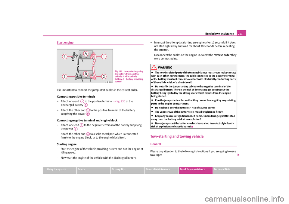
Start engineIt is important to connect the jump
-start cables in the correct order.
Connecting positive terminals – Attach one end to the positive terminal
⇒
fig. 230
of the
discharged battery .
– Attach the other end to the positive terminal of the battery
supplying the power .
Connecting negative term
inal and engine block
– Attach one end to the negative
terminal of the battery supplying
the power .
– Attach the other end to a solid metal part which is connected
firmly to the engine block, or
to the engine block itself.
Starting engine – Start the engine of the vehicle providing current and run the engine at
idling speed.
– Now start the engine of the vehicle with the discharged battery.
– Interrupt the attempt at starting an engine after 10 seconds if it does
not start right away and wait for about 30 seconds before repeating the attempt.
– Disconnect the cables on the engine in exactly the
reverse order
they
were connected up.
WARNING
•
The non-insulated parts of the terminal clamps must never make contact
with each other. Furthermore, the cable connected to the positive terminal of the battery must not come into contact with electrically conducting parts of the vehicle - risk of a short circuit!•
Do not affix the jump starting cables to the negative terminal of the
discharged battery. There is the risk
of detonating gas seeping out the
battery being ignited by the strong
spark which results from the engine
being started.•
Run the jump-start cables so that th
ey cannot be caught
by any rotating
parts in the engine compartment.•
Do not bend over the batteries - risk of caustic burns!
•
The vent screws of the battery cells must be tightened firmly.
•
Keep any sources of ignition (naked
flame, smouldering cigarettes etc.)
away from the battery - risk of an explosion!•
Never jump-start the batteries which have a too low electrolyte level -
risk of explosion and caustic burns!Tow-starting and towing vehicleGeneralPlease pay attention to the following in
structions if you are going to use a
tow rope:
Fig. 230 Jump-starting using the battery from another vehicle: A - flat vehicle battery, B - battery providing current
A1AAA2AB
A3
AB
A4
se0.1.book Page 253 Frida
y, April 10, 2009 3:19 PM
Page 260 of 304

Fuses and light bulbs
259
Using the system
Safety
Driving Tips
General Maintenance
Breakdown assistance
Technical Data
Fuse cover in engine compartment The fuse box in the engine comp
artment exists in two different
versions. You can determine which version your vehicle is fitted with after removing the fuse cover at the location of the fuses.On some vehicles, the battery cover
must be removed before removing
the fuse cover
⇒
page 232.
Removing fuse cover – Move the circlips
⇒
fig. 238
as far as the stop, the symbol
appears behind the circlip and remove the cover.
Installing fuse cover – Position the fuse cover on the fuse box and push the circlips as far
as the stop - the symbol
is visible behind the circlip.
Caution
•
When unlocking and locking the fuse cover,
it must be pressed on the sides to
the box, otherwise damage can
occur to the locking mechanism.
•
Carefully position the fuse cover in th
e engine compartment. If the cover was
not correctly positioned, water can get into
the fuses and this results in a damage
to the vehicle!
Fuse assignment in engine compartmentCertain electrical components are only standard on certain vehicle model versions or only suppliable as optional
equipment for certain models.
Fig. 238 Fuse cover in engine compartment
AA
AA
No.
Power consumer
Amperes
F1
Not assigned
F2
Control unit for automatic gearbox DQ 200
30
F3
Measuring circuit
5
F4
Valves for ABS
30/20
F5
Control unit for automatic gearbox
15
F6
Instrument cluster, windshield
wiper lever and turn sig-
nal light lever
5
F7
Power suppy terminal 15, Starter
40
F8
Radio
15
F9
Phone
5
F10
Engine control unit, Main relay
5/10
F11
Control unit for auxiliary heating
20
F12
Control unit for CAN databus
5
Fig. 239 Schematic repre- sentation of fuse carrier in engine compartment
se0.1.book Page 259 Frida
y, April 10, 2009 3:19 PM
Page 261 of 304

Fuses and light bulbs
260
Fuse assignment in the dash panelCertain electrical components are only standard on certain vehicle model versions or only suppliable as optional
equipment for certain models.
F13
Engine control unit
15/30
F14
Ignition
20
F15
Lambda probe NO
x sensor, fuel pump relay
Glow plug system relay
10 15 5
F16
Central control unit, right main headlight, right rear light unit
30
F17
Horn
15
F18
Amplifier for digital sound processor
30
F19
Front window wiper
30
F20
Water pumpvalve for fuel dosing
1020
F21
Lambda probe
10/15
F22
Clutch pedal switch, brake pedal switch
5
F23
Secondary air pump Air mass meter Fuel high pressure pump
5 10 15
F24
Activated charcoal filter, ex
haust gas recirculation valve
10
F25
Pump for ABS
30/40
F26
Central control unit, left main headlight, left rear light unit
30
F27
Secondary air pump Glow plug system
4050
F28
Not assigned
F29
Power supply terminal 30
50
F30
Te r m i n a l X
a)
50
a)In order not to drain the battery unnecessarily
when starting the engine, the electrical com-
ponents of this terminal are automatically switched off.No.
Power consumer
Amperes
No.
Power consumer
Amperes
1
Diagnostic socket, Engine co
ntrol unit, Electrical fuel
pump
10
2
Control unit for ABS, ESP
5
3
Airbag
5
4
Heating, Air conditioning system, Reversing lights
5
5
Control unit for headla
mp beam adjustment
5
6
Instrument cluster, Control unit for automatic gearbox, Control unit for electromec
hanical power steering,
Parking aid; Haldex clutch
5
7
Not assigned
8
Not assigned
9
Not assigned
10
Not assigned
11
Not assigned
Fig. 240 Schematic repre- sentation of the fuse carrier in the dash panel
se0.1.book Page 260 Frida
y, April 10, 2009 3:19 PM