change time SKODA OCTAVIA 2010 2.G / (1Z) User Guide
[x] Cancel search | Manufacturer: SKODA, Model Year: 2010, Model line: OCTAVIA, Model: SKODA OCTAVIA 2010 2.G / (1Z)Pages: 275, PDF Size: 16.43 MB
Page 133 of 275
Communication
132
Music playback via Bluetooth
®
The universal telephone preinstallation GSM II makes it possible to play back music via
Bluetooth
® from the devices such as MP3 pl ayer, mobile phone or notebook.
In order to enable the music playback via Bluetooth
®, it is necessary to connect the
device with the handsfree-system in the menu Phone - Bluetooth - Media player .
The operation of the music pl ayback from the connected de vice can be performed via
the hands-free system with the voice control page 131 or directly via the connected
device.
Note
The device to be connected must support the Bluetooth
® profile A2DP, see Owner's
manual of the device to be connected.
Universal telephone preinstallation GSM IIl*IntroductionThe universal telephone preinstallation GSM IlI is a built-in “hands-free system”, it
provides a voice operated convenience mode via the multifunction steering wheel* or
the navigation system*.
All communication between a telephone and the hands-free system of your vehicle
can only be established with the help of the Bluetooth
®, when using HFP - Hands Free
Profile or rSAP - remote SIM Access Profile .
The following functions are included in th e universal telephone preinstallation GSM III:
Phone Phonebook page 132.
Convenience mode with the multifunction steering wheel* page 134 with
display in the information display page 136.
Voice control of the telephone, including the language selection of the telephone
contacts page 137.
Internet connection page 138.
Music playback from the telephone or other multimedia units page 139.
Display of SMS page 136.
The volume can be changed at any time with the control button of the radio* or with
the buttons on the multifunction steering wheel*.
WARNING
Pay attention primarily to the traffic situation! As the driver you are fully
responsible for road safety. Use the telephone system only to such an extent, so
that you are in full control of your vehicle at any time.
Note
Please also refer to the additional instructions page 125, “Mobile phones and
two-way radio systems”.
Should you have any questions, please contact an authorised Škoda Service
Par tner.
Phone PhonebookA phone phonebook is part of the mobile ph one preinstallation with voice control. In
the phone phonebook there are 2000 free me mory locations available. This phone
phonebook can be used in line with the mobile telephone.
After the first connection of the telephone, the system begins to load the phone book
from the phone and the SIM card into the memory of the control unit.
If the telephone book of the mobile phon e contains more than 2 000 entries, the
system announces after downloading Phone book not fully loaded.
Each time the telephone has establishe d a new connection with the hands-free
system, an update of the relevant phone b ook is performed. The updating can take a
few minutes. During this time the phone book, which was stored after the last update
was completed, is available. Newly stored telephone numbers are only shown after the
updating has ended.
If a telephone event (e.g. incoming or outg oing call, dialogue of the voice control)
occurs during the updating procedure, the updating is interrupted. After the telephone
event has ended, the updating starts anew.
s43s.1.book Page 132 Thursday, May 13, 2010 1:21 PM
Page 138 of 275
Communication137
Using the system
Safety
Driving Tips
General Maintenance
Breakdown assistance
Technical Data
Signal settings
Ring tone
Volume
Phone settings
Select operator
Automatic
Manual
Network mode
Off time
SIM mode - applies to telephones with the rSAP profile in which two SIM cards
can be inserted - there is the possibility to select which SIM card may be connected
with the hands-free system and the possibility to select the name for the SIM card.
SIM mode 1
SIM mode 2
GPRS - You can ask a network provider about the settings of the access point for an
internet connection
Switch off ph. - switching off the telephone unit (telephone remains connected)
Back
Return in the main menu of the information display.
Voice controlIntroductionThe period, in which the telephone system is ready to receive voice commands and
carry out the voice commands, is called DI ALOGUE. The system gives audible feedback
and guides you if necessary through the relevant functions.
The volume can be changed at any time with the control button of the radio* or the
navigation system* or with the buttons on the multifunction steering wheel*. Switch on voice control (dialogue)
You can start the dialogue at any time
by briefly pressing the PTT button
on the
multifunction st eering wheel* page 134.
If the system does not recognise your command, it repeats the first part of the aid and
thus a new entry is possible. After the 2nd error the system repeats the second part of
the aid. After the 3rd error the answer “ Procedure cancelled” is given and the dialogue
is ended.
Switching off voice control (dialogue)
You can end the dialogue at an y time by briefly pressing the button on the multifunc-
tion steering wheel* page 134. If the system expects a voice command, you can end
the dialogue with the command CANCEL.
Only the message just repeated can be ended by pressing the PTT button during the
message and thus it is possible to pronounce the expected command sooner.
The dialogue of the incoming call is immediately interrupted and you can accept the
call by pressing the button
on the multifunction steering wheel*.
Optimum understanding of the voice commands depends on the following
factors:
Speak with a normal tone of voice withou t intonation and excessive voice pauses.
Avoid insufficient articulation.
Close the doors, windows and sliding roof, in order to reduce or stop disturbing
exterior noise.
It is recommended to speak louder at higher speeds, so that the tone of your voice
is louder than the increased surrounding noise.
During the dialogue avoid additional noise in the vehicle, e.g. simultaneously
talking occupants.
Do not speak, if the system makes an announcement.
The microphone for voice control is inserted in the moulded headliner and
directed to the driver and front passenger. Therefore the driver and the front passenger
can operate the equipment.
s43s.1.book Page 137 Thursday, May 13, 2010 1:21 PM
Page 140 of 275
Communication139
Using the system
Safety
Driving Tips
General Maintenance
Breakdown assistance
Technical Data
– On the device to be connected, enter the password and follow any instructions
given on this device or in the information display.
– Enter the desired internet address in the internet browser. The operating system requests the entry of the telephone number for the internet access (depending on
the operator, usually “*99#”).
Music playback via Bluetooth
®
The universal telephone preinstallation GSM IIl makes it possible to play back music via
Bluetooth
® from the devices such as MP3 player, mobile phone or notebook.
In order to enable the music playback via Bluetooth
®, it is necessary to connect the
device, which should be connected, with the hands-free system in the menu Phone -
Bluetooth - Media player .
The music playback process is performed on the connected device.
Note
The device to be connected must support the Bluetooth
® profile A2DP, see Owner's
manual of the device to be connected.
MultimediaInputs AUX-IN* and MDI*The input AUX-IN is located below the armrest* of the front seats and is marked with
.
The input MDI is located in the storage compartment on the front passenger side.
The inputs AUX-IN and MDI connect the ex ternal audio sources (e.g. iPod or MP3
player) and play back music fr om these devices via your radio* or navigation system*
installed in the factory.
The description of the operation can be found in the relevant Owner's Manual of your
radio* or your navigation*.
Note
The loudspeakers in the vehicle are matched to a power output of the radio and
navigation system of 4x 20°W.
For the equipment sound system*, the loudspeakers are matched to a power
output of the amplifier of 4x40°W + 6x20 W.
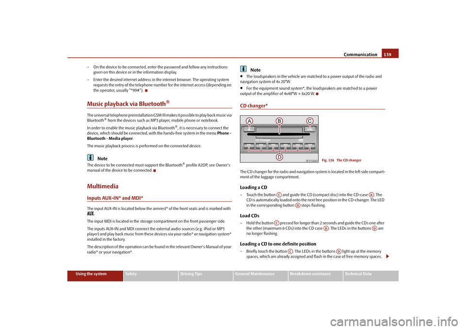
CD changer*The CD changer for the radio and navigation system is located in the left side compart-
ment of the luggage compartment.Loading a CD– Touch the button and guide the CD (compact disc) into the CD-case . The CD is automatically loaded onto the next free position in the CD-changer. The LED
in the corresponding button stops flashing.Load CDs– Hold the button pressed for longer than 2 seconds and guide the CDs one after
the other (maximum 6 CDs) into the CD case . The LEDs in the buttons are
no longer flashing.Loading a CD to one definite position– Briefly touch the button . The LEDs in the buttons light up at the memory spaces, which are already assigned and flash in the case of free memory spaces.
Fig. 126 The CD changer
AC
AB
AD
AC
AB
AD
AC
AD
s43s.1.book Page 139 Thursday, May 13, 2010 1:21 PM
Page 147 of 275
Seat belts
146
The speed of the vehicle is, nevertheless, the most important factor. Doubling the
speed of the vehicle from 25 km/h up to 50 km/hour increases the kinetic energy four
times.
The common opinion that it is possible to su pport your body in a minor accident with
your hands, is incorrect. Even in a collision at only a low speed, the forces acting on the
body are such that it is no longer possible to support your body.
Even if you only drive at a speed within the range from 30 km/hour to 50 km/hour, the
forces which are produced on your body in the event of an accident can easily exceed
10.000 N (Newton). This equals a weight of one tonne (1 000 kg).
In the event of a frontal collision, occupants of the vehicle not wearing a seat belt, are
thrown forward and strike in an uncontrolled way parts of the interior of the vehicle,
such as steering wheel, dash panel, windscreen, page 145, fig. 129 - left. The occu-
pants of a vehicle who have not fastened their seat belts may even be thrown out of
the vehicle. This can result in fatal injuries.
It is also important that rear seat occupants fasten their seat belts as they will otherwise
be thrown through the vehicle in an uncontr olled manner in the event of an accident
A rear seat passenger who has not fastened the s eat bel t i s a dang er not o nl y to hims elf
but also for those seated at the front page 145, fig. 129 - right.Important safety information regarding the use of seat beltsThe correct use of the seat belts cons iderably reduces the risk of injury!
WARNING
The belt webbing must not be jammed in-between at any point or twisted,
or chafe against any sharp edges.
It is important that the belt webbing is properly routed if the seat belts are
to offer their maximum protection page 147.
No two persons (also not children) should ever use a single seat belt
together.
The maximum protection which seat belts can offer is only achieved if you
are correctly seated page 142, “Correct seated position”.
The belt webbing must not run across solid or fragile objects (e.g. specta-
cles, ball-point pens, keys etc.) as this may be a cause of injuries.
Bulky, loose clothing (e.g. a winter coat over a jacket) does not allow you to
be correctly seated and impairs proper operation of the seat belts.
It is prohibited to use clamps or other objects to adjust seat belts (e.g. for
shortening the belts for smaller persons).
The lock tongue should only be inserted into the lock which is the correct
one for your seat. Wrong use of the safety belt will reduce its capacity to protect
and the risk of injury increases.
The seat backrests of the front seats must not be tilted too far to the rear
otherwise the seatbelts can lose their effectiveness.
The belt webbing must always be ke pt clean. Soiled belt webbing may
impair proper operation of the inertia reel page 191, “Seat belts”.
The slot of the belt tongue must not be blocked by paper or similar objects
otherwise the belt tongue will not lock in place properly.
Inspect the seat belts regula rly to ensure they are in good condition. If you
find seat belts which have damage to the seat belt webbing, seat belt connec-
tions, to the inertia reels or to the lock, the relevant safety belt must be replaced
by a specialist garage.
The seat belts must not be removed or changed in any way. Do not make an
attempt to repair the seat belts yourself.
Damaged seat belts which have been subjected to stress in an accident and
were therefore stretched, must be replaced - this is best done by a specialist
garage. The anchorage points of the belts must also be inspected. The
anchorage points for the belts should also be checked.
In certain countries it is possible to use seat belts which differ in terms of
their operation from the seat belts which are described on the pages which
follow.WARNING (continued)
s43s.1.book Page 146 Thursday, May 13, 2010 1:21 PM
Page 154 of 275
Airbag system153
Using the system
Safety
Driving Tips
General Maintenance
Breakdown assistance
Technical Data
passenger seat where the child is seated
with its back facing in direction of
travel (in some countries also when the child is facing the direction of travel). If
this is not done, there is a risk of the ch ild suffering severe or even fatal injuries
if the front passenger airbag is deploy ed. In certain countries national legal
provisions also require that the side or head passenger airbags be deactivated.
When transporting a child on the front passenger seat, please comply with the
appropriate national regu lations regarding the use of child safety seats.
There must not by any further persons, animals or objects positioned
between the front seated occupants and the deployment area of the airbag.
The steering wheel and the surface of the airbag module in the dash panel
on the passenger side must not be stuck onto, covered or modified in any other
way. These parts should only be cleaned with a dry cloth or a cloth moistened
with water. No objects such as cup holders, mobile phone mounts, etc. may be
attached to the covers of the airbag modules or be located within the imme-
diate area.
No modifications of any kind may be made to parts of the airbag system.
Any work on the airbag system includ ing installing and removing system
components because of other repair wo rk (e.g. removing the steering wheel)
must only be carried out by a specialist garage.
Never carry out changes on the front bumper or on the body.
Never place any objects on the surface of the front passenger airbag module
in the dash panel.
Side airbags*Description of side airbags
The side airbag together with the head airbag offers enhanced occu-
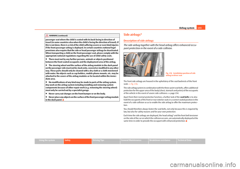
pant protection in the event of a side collision.The front side airbags are housed in the upholstery of the seat backrests of the front
seats fig. 136 .
The side airbag system in combination with the three-point seat belts, offers additional
protection for the upper area of the body (chest, stomach and pelvis) of the occupants
of the vehicle in the event of severe side collisions page 154.
Apart from their normal protective function, a further task of the seat belts is to also
hold the occupents of the front or rear exteri or seats in a correct seated position in the
event of a side collision so as to enable th e side airbag to offer the maximum protec-
tion.
You should therefore always fasten the seat belts, not only because this is required by
law, but also for safety reasons and for your own protection.
Each time the side airbags are deployed, th e head airbag* and the front belt tensioner
on the side of the car on which the collision occures, are automatically deployed at the
same time in order to provide the occupant with enhanced protection.
WARNING (continued)
Fig. 136 Installation position of side
airbag in driver seat
s43s.1.book Page 153 Thursday, May 13, 2010 1:21 PM
Page 158 of 275
Airbag system157
Using the system
Safety
Driving Tips
General Maintenance
Breakdown assistance
Technical Data
being deployed. When the deployed head airbag is inflated, parts of the acces-
sories fitted may in certain circumstances be thrown into the interior of the car
and cause injuries to the occupants
page 214, “Accessories, changes and
replacement of parts”.
Any work on the head airbag system including installing and removing
system components because of other repair work (e.g. removing headliner)
must only be carried out by a specialist garage.
Deactivating an airbagDeactivating airbags
If any airbags have been deactivated, switch them on again as soon as
possible so that they are able to again provide their proper protection.There is the technical means installed within your vehicle to switch off the front, side*
or head* airbag (take out of commission).
This is why you should have the deactivation of the airbags carried out by a specialist
garage.
On vehicles equipped with the switch for de activation of the airbags, you can deacti-
vate the front passenger airbag by means of this switch page 157.
Deactivation of airbags is envisaged only for particular instances, such as if:
you must in exceptional cases use a child seat on the front passenger seat where
the child has its back to the direction of tr avel of the vehicle (in some countries this
must be in the direction of travel due to other legal regulations applying) page 159,
“Important safety information regarding the use of child safety seats”,
you are not able to maintain the distan ce of at least 25 cm between middle of
steering wheel and chest, despite the driver seat being correctly adjusted,
special attachments are required in the ar ea of the steering wheel because of a
physical disability,
you have installed other seats (e.g. orthopaedic seats without side airbags). Monitoring the airbag system
The functionality of the airbag system is al
so monitored electronically when one airbag
has been switched off.
If the airbag was switched off using diagnostic equipment:
The warning light for the airbag system li ghts up for 4 seconds after switching on
the ignition and then flashes for 12 seconds afterwards in 2 second intervals.
The following situation applies if the ai rbag has been switched off using the
switch for the airbag* in the storage compartment:
the airbag indicator light in the instrume nt cluster comes on for about 4 seconds
each time the igniti on is switched on,
if the airbags are switched off, this is in dicated in the middle of the dash panel by
the lighting up of the indicator light
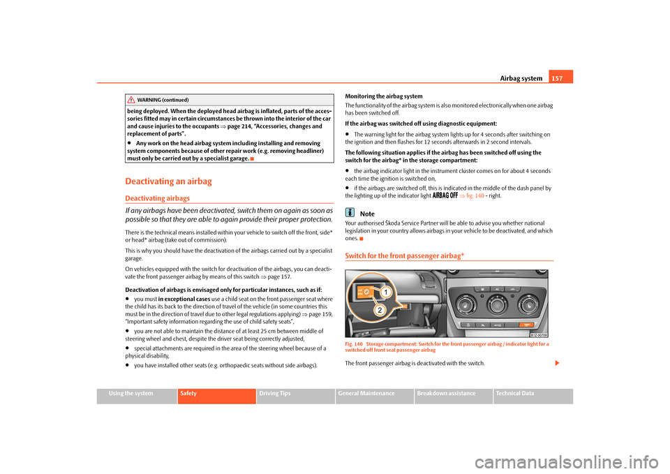
fig. 140 - right.
Note
Your authorised Škoda Service Partner will be able to advise you whether national
legislation in your country allows airbags in your vehicle to be deactivated, and which
ones.Switch for the front passenger airbag*Fig. 140 Storage compartment: Switch for the front passenger airbag / indicator light for a
switched off front seat passenger airbagThe front passenger airbag is deactivated with the switch.
WARNING (continued)
s43s.1.book Page 157 Thursday, May 13, 2010 1:21 PM
Page 169 of 275
Intelligent Technology
168
offered must not tempt you to take greater risks than otherwise - risk of an acci-
dent!
Note
All four wheels must be fitted with the same tyres in order to achieve problem-free
operation of the ESP. Differing rolling circum ferences of the tyres can lead to an unde-
sirable reduction in the engine output.
Changes to vehicle (e.g. on engine, on th e brakes, on chassis or another combina-
tion of tyres and wheels) can influence the function of the ESP page 214, “Accesso-
ries, changes and replacement of parts”.
Electronic Differential Lock (EDL and XDL)*
The electronic differential lock prev ents an individual wheel from slip-
ping.Models fitted with ESP ar e equipped with electronic differential lock (EDL).
General
The EDL makes it much easier, and sometimes at all possible, to start off, accelerate
and climb a steep hill when the conditions of the road surface are unfavourable.
Operating principle
The EDL is activated automaticall y, that is without any action on the part of the driver.
It monitors the speeds of the driven wheels with the aid of the ABS sensors. Should
only one drive wheel begin spinning on a slippery surface there will be an appreciable
difference in the speed of the driven wheels. The EDL function brakes the slipping
wheel and the differential transmits a greate r driving force to the other driven wheel.
This control process is also accompanied by noises.
Overheating of the brakes
The EDL switches off automatica lly if unusually severe stresses exist in order to avoid
excessive heat generation in the disc brake on the wheel which is being braked. The
vehicle can continue to be driven and has the same characteristics as a vehicle not
fitted with EDL. The EDL switches on again automatically
as soon as the brake has cooled down.
XDL function (only for Octavia RS)
The XDL function is an extension to the electronic differential lock. The XDL function
does not respond to traction, but to the relief of the inner front wheel during fast
cornering. An active brake intervention on the brake of the inner wheel prevents it from
spinning. Thus, the trac tion is improved and the vehicle continues to follow the desired
track.
WARNING
Carefully depress the accelerator when accelerating on uniformly slippery
road surfaces, such as ice and snow. Th e driven wheels might still spin despite
the EDL and affect the stability of the vehicle - risk of an accident!
You should always adapt your style of driving to the condition of road
surface and to the traffic situation even when your vehicle is fitted with EDL.
The increased safety offered must not tempt you to take greater risks than
otherwise - risk of an accident!Note
If the ABS or ESP warning light comes on, this may also indicate a fault in the EDL.
Please have the vehicle inspected as soon as possible by a specialist garage.
Changes to vehicle (e.g. on engine, on the brakes, on chassis or another combina-
tion of tyres and wheels) can influence the function of the EDL page 214, “Accesso-
ries, changes and replacement of parts”.
WARNING (continued)
s43s.1.book Page 168 Thursday, May 13, 2010 1:21 PM
Page 170 of 275
Intelligent Technology169
Using the system
Safety
Driving Tips
General Maintenance
Breakdown assistance
Technical Data
Traction control system (TCS)
The traction control system prevents the driven wheels from spinning
when accelerating.General
The TCS makes it much easier, and sometimes at all possible, to start off, accelerate and
climb a steep hill when th e conditions of the road surface are unfavourable.
Operating principle
The TCS switches on automatically when th e engine is started and then conducts a
self-test. The system monitors the speeds of the driven wheels with the aid of the ABS
sensors. If the wheels are spinning, the force transmitted to the road surface is auto-
matically adapted by reducing the engine speed. The system operates at all speeds.
The TCS operates in combination with the ABS page 171, “Antilock brake system
(ABS)”. The TCS will not function if a fault exists in the ABS system.
The TCS warning light lights up in the instru ment cluster when there is a fault on the
TCS
page 32.
During an intervention of the system, the TCS warning light
flashes in the instru-
ment cluster page 32.
Switching off
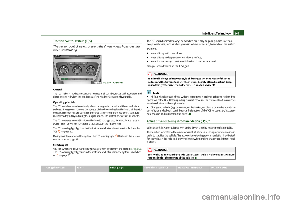
You can switch the TCS off and on again as you wish by pressing the button fig. 150 .
The TCS warning light lights up in the instru ment cluster when the system is switched
off
page 32. The TCS should normally always
be switched on. It may be good practice in certain
exceptional cases, such as when you wish to have wheel slip, to switch off the system.
Examples:
when driving with snow chains,
when driving in deep snow or on a loose surface,
when it is necessary to rock a vehicle when it has become stuck.
then you should switch on the TCS again.
WARNING
You should always adjust your style of driving to the conditions of the road
surface and the traffic situation. The increased safety offered must not tempt
you to take greater risks than otherwise - risk of an accident!
Note
All four wheels must be fitted with the same tyres in order to achieve problem-free
operation of the TCS. Differing rolling circumferences of the tyres can lead to an unde-
sirable reduction in the engine output.
Changes to vehicle (e.g. on engine, on the brakes, on chassis or another combina-
tion of tyres and wheels) can influence the function of the TCS page 214, “Accesso-
ries, changes and replacement of parts”.
Active driver-steering recommendation (DSR)*Vehicles with ESP are equipped with active driver-steering recommendation (DSR).
This function indicates to the driver in crit ical situations a steering recommendation in
order to stabilise the vehicle. The active driver-steering recommendation is activated,
for example, on the right and left vehicle si de when braking sharply on different road
surfaces.
WARNING
Even with this function the vehicle cann ot steer itself! The driver is furthermore
responsible for the steering of the vehicle!
Fig. 150 TCS switch
s43s.1.book Page 169 Thursday, May 13, 2010 1:21 PM
Page 172 of 275
Intelligent Technology171
Using the system
Safety
Driving Tips
General Maintenance
Breakdown assistance
Technical Data
Brake boosterThe brake booster boosts the pressure which you generate with the brake pedal. The
necessary pressure is only genera ted when the engine is running.
WARNING
Never switch off the engine before the vehicle is stationary.
The brake booster only operates when the engine is running. Greater phys-
ical effort for braking is required when en gine is switched off. Because if you do
not stop as normal, this can cause an accident and severe injuries.
Antilock brake system (ABS)ABS prevents the wheels locking when braking.General
The ABS contributes significantly to enhanc ing the active safety of your vehicle.
Compared to a vehicle not fitted with the ABS brake system, you are able to retain
optimal steering ability even during a full br ake application on a slippery road surface
because the wheels do not lock up.
You must not expect, however, that the br aking distance will be shorter under all
circumstances as a result of the ABS. The braking distance for example on gravel and
fresh snow, when you should anyway be driving slowly and cautiously, will be longer.
Operating principle
The brake pressure will be reduced on a wheel which is rotating at a speed which is too
low for the speed of the vehicle and tending to lock. This control cycle is noticeable
from a pulsating movement of the brake pedal which is accompanied by noises.
This is consciously intended to provide the driver with the information that the wheels
are tending to lock (ABS control range) . You must always keep the brake pedal
depressed to enable the ABS to optimally control the brake application in this braking
range. Never interrupt the application of the brakes!
WARNING
The ABS can also not overcome the physical limits of your vehicle. Please do
not forget this, particularly when driving on icy or wet road surfaces. If the ABS
is operating within the control range, adapt your speed immediately to the
conditions of the road surface and the traffic situation. The increased safety
offered by the ABS must not tempt you to take greater risks than otherwise -
risk of an accident!
The normal braking system is still fully functional if there is an ABS fault.
Visit a specialist garage as quickly as poss ible and adjust your style of driving to
take account of the ABS fault in the meantime since you will not know the extent
of the fault and in how far the braking efficiency is affected.Note
A warning light comes on if a fault occurs in the ABS system
page 33.
Changes to vehicle (e.g. on engine, on the brakes, on chassis or another combina-
tion of tyres and wheels) can in fluence the function of the ABS page 214, “Accesso-
ries, changes and replacement of parts”.
Brake Assist*During a severe brake application (e.g. if a hazard exists), the Brake Assist increases the
braking force and thus makes it possible to rapidly produce the pressure required in
the brake system.
The majority of drivers do a pply the brakes in good time in dangerous situations, but
do not depress the brake pedal with sufficient pressure. Consequently, it is not possible
for the vehicle to achieve its maximum deceleration and the vehicle covers a greater
distance than necessary.
The Brake Assist is activated by the very qu ick operation of the brake pedal. In such
cases, a much greater braking pressure exists than during a normal brake application.
This makes it possible, even with a relatively low resistance of the brake pedal, to
produce an adequate pressure in the brake system in the shortest possible time, which
is required for maximum dece leration of the vehicle. You must apply the brake pedal
firmly and hold it in this position in or der to achieve the shortest possible braking
distance.
s43s.1.book Page 171 Thursday, May 13, 2010 1:21 PM
Page 174 of 275
Intelligent Technology173
Using the system
Safety
Driving Tips
General Maintenance
Breakdown assistance
Technical Data
one wheel per axle was changed.
Basic setting of the system
After changing the tyre inflation pressures, after changing one or several wheels, the
position of a wheel on the vehicle (e.g. exch anging the wheels between the axles) or
when the warning light lights up while drivin g, a basic setting of the system must be
carried out as follows.
Inflate all tyres to the specified inflation pressure page 208.
Switch on the ignition.
Press button page 172, fig. 151 for more than 2 seconds. While pressing
the button, the warning light
lights up. At the same time the memory of the system
is erased and the new calibration is started, which is confirmed with an audible signal
and then the warning light
goes out.
If the warning light
does not go out after the basic setting, there is a fault in the
system. Have the vehicle inspected by your nearest specialist garage.
Warning light
lights up
If the tyre inflation pressure of at least one wheel is insufficiently inflated in comparison
to the stored basic value, the warning light
lights up.
Warning light
flashes
If the warning light flashes, there is a system fault. Have the vehicle inspected by your
nearest specialist garage.
WARNING
When the warning light
lights up, immediately reduce the speed and
avoid sudden steering and brake manoeuvr es. Please stop the vehicle without
delay at the nearest possible stop and in spect the tyres and their inflation pres-
sures.
The driver is responsible for the correct tyre inflation pressures. For this
reason, the tyre inflation pressu res must be checked regularly.
Under certain circumstances (e.g. sporty style of driving, wintry or unpaved
roads) the warning light
can be delayed or does not light up at all.
The tyre pressure monitoring system does not take away the responsibility
from the driver for the correct tyre inflation pressure.
Note
The tyre pressure monitoring system:
does not replace the regular tyre inflatio n pressure control, because the system
cannot detect an even pressure loss,
cannot warn in case of very rapid tyre inflation pressure loss, e.g. in case of sudden
tyre damage. In this case ca refully bring the vehicle to a standstill without sudden
steering movements and without sharp braking.
In order to ensure a proper functioning of the tyre inflation pressure-control
system, it is necessary to carry out the ba sic setting again every 10 000 km or 1x a
year.
Diesel particle filter* (diesel engine)In the diesel particle filter the resu lting soot particles are collected and
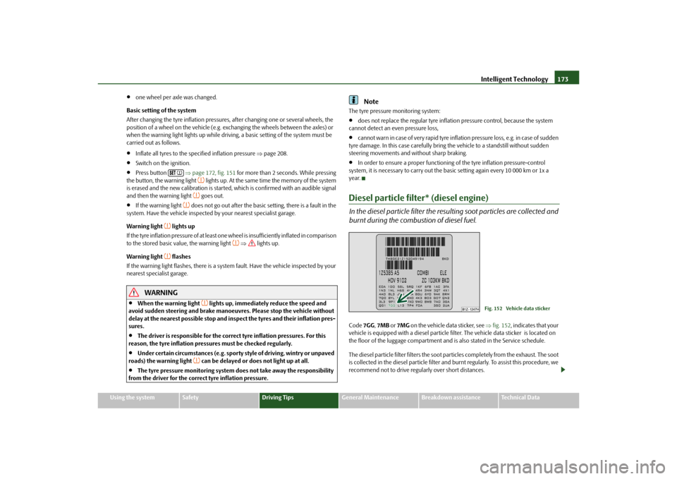
burnt during the combustion of diesel fuel.Code 7GG, 7MB or 7MG on the vehicle data sticker, see fig. 152 , indicates that your
vehicle is equipped with a diesel particle fi lter. The vehicle data sticker is located on
the floor of the luggage compartment and is also stated in the Service schedule.
The diesel particle filter filters the soot particles completely from the exhaust. The soot
is collected in the diesel particle filter and burnt regularly. To assist this procedure, we
recommend not to drive regu larly over short distances.
Fig. 152 Vehicle data sticker
s43s.1.book Page 173 Thursday, May 13, 2010 1:21 PM