technical data SKODA OCTAVIA 2011 2.G / (1Z) Owner's Manual
[x] Cancel search | Manufacturer: SKODA, Model Year: 2011, Model line: OCTAVIA, Model: SKODA OCTAVIA 2011 2.G / (1Z)Pages: 248, PDF Size: 3.79 MB
Page 199 of 248
Accessories, changes and replacement of parts
General ŠKODA vehicles have been built according to the latest discoveries in safety engi-
neering. Thus one should not change the condition in which the vehicle was deliv-
ered from the manufacturer without some thought.
If you want to retrofit the vehicle with accessories, if a vehicle part is to be re-
placed with a new one, or when needing to make technical changes, the following
instructions must be observed:
● Advise should always be obtained from an authorised ŠKODA Service Partner
before buying any accessories or parts and before making any technical changes
⇒ .
● The guidelines and instructions issued by ŠKODA must be observed when
making technical changes.
Adhering to the prescribed procedures will prevent any kind of damage to the ve-
hicle, and its travelling and operating safety will be maintained. The vehicle also
complies with German road transport regulations (StVZO). More information is
available from an authorised
ŠKODA Service Partner who can also perform the
necessary work properly.
Interference on the electronic components and their software can lead to opera-
tional faults. This interference can also impair not directly affected systems be-
cause of the networking of the electronic components. In other words, the vehi-
cle's roadworthiness may be put at risk and increased wear on parts may arise.
Any damage which is done caused by technical changes made without consult-
ing a ŠKODA dealer is excluded from the warranty – see the warranty certificate. WARNING
● Work or modifications on your vehicle, which have been carried out unpro-
fessionally, can cause operational faults - risk of accident!
● We advise you, in your own interest, to only use ŠKODA Original Accesso-
ries and ŠKODA Original Parts which have been expressly approved for use on
your vehicle. Reliability, safety and suitability have been established for
ŠKODA Original Accessories and ŠKODA
Original Parts.
● Although we constantly monitor the market, we are not able to assess or
warrant the parts even though in some instances such parts may have a type
approval or may have been approved by a nationally recognised testing labo-
ratory. Note
● ŠKODA Original Accessories and
ŠKODA Original Parts can be bought from au-
thorised ŠKODA Service Partners who also professionally undertake the assembly
of parts which were purchased there.
● We recommend having all work undertaken by an authorised ŠKODA Service
Partner.
● All ŠKODA Original Accessories and Original Parts from the Original Accessories
catalogue, such as a towing device, child seats, etc. are authorised.
● We recommend that you also buy car stereos, aerials or other electrical acces-
sories from an authorised
ŠKODA Service Partner, who should also carry out the
installation. 197
Accessories, changes and replacement of parts Using the system Safety Driving Tips General Maintenance Breakdown assistance Technical data
Page 201 of 248
The fire extinguisher must be checked by an authorised person or company annu-
ally (please observe the differing legal requirements).
WARNING
If the fire extinguisher is not correctly attached, in case of sudden manoeu-
vres or an accident it can be “thrown” through the interior compartment and
cause injuries. Note
● The fire extinguisher must comply with the relevant and valid legal require-
ments.
● Pay attention to the expiration date of the fire extinguisher. If the fire extin-
guisher is used after the expiration date, its proper function is no longer assured.
● The fire extinguisher is only supplied in certain countries within the scope of
delivery.
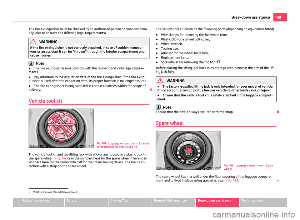
Vehicle tool kit Fig. 162 Luggage compartment: Storage
compartment for vehicle too kit
The vehicle tool kit and the lifting jack with sticker are housed in a plastic box in
the spare wheel ⇒ fig. 162 or in the compartment for the spare wheel. There is al-
so space here for the removable ball for the trailer towing device. The box is at-
tached with a strap on the spare wheel. The vehicle tool kit contains the following parts (depending on equipment fitted):
● Wire clamps for removing the full wheel trims,
● Plastic clip for a wheel bolt cover,
● Wheel wrench,
● Towing eye,
● Adapter for the wheel bolts lock,
● Replacement lamp,
● Screwdriver for removing the fog lights 1)
.
Before placing the lifting jack back in its storage area, screw in the arm of the lift-
ing jack fully. WARNING
● The factory-supplied lifting jack is only intended for your model of vehicle.
On no account attempt to lift a heavier vehicle or other loads - risk of injury!
● Ensure that the vehicle tool kit is safely attached in the luggage compart-
ment. Note
Ensure that the box is always secured with the strap.
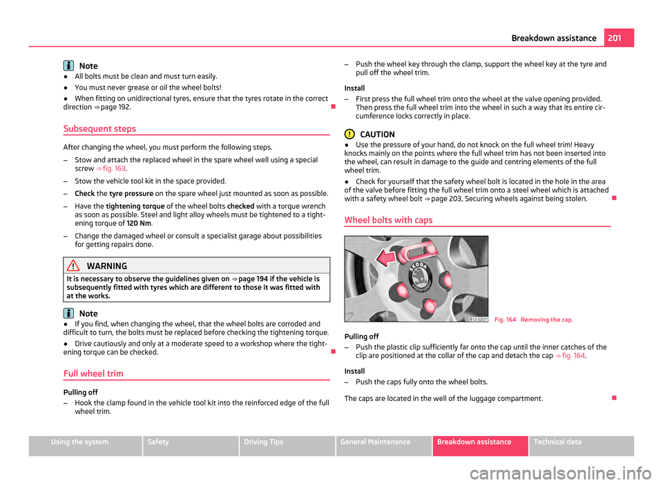
Spare wheel Fig. 163 Luggage compartment: Spare
wheel
The spare wheel lies in a well under the floor covering of the luggage compart-
ment and is fixed in place using special screws ⇒
fig. 163. £1)
Valid for Octavia RS and Octavia Scout. 199
Breakdown assistance Using the system Safety Driving Tips General Maintenance Breakdown assistance Technical data
Page 203 of 248
Note
● All bolts must be clean and must turn easily.
● You must never grease or oil the wheel bolts!
● When fitting on unidirectional tyres, ensure that the tyres rotate in the correct
direction ⇒ page 192
.
Subsequent steps After changing the wheel, you must perform the following steps.
–
Stow and attach the replaced wheel in the spare wheel well using a special
screw ⇒ fig. 163 .
– Stow the vehicle tool kit in the space provided.
– Check the tyre pressure on the spare wheel just mounted as soon as possible.
– Have the tightening torque of the wheel bolts checked with a torque wrench
as soon as possible. Steel and light alloy wheels must be tightened to a tight-
ening torque of 120 Nm.
– Change the damaged wheel or consult a specialist garage about possibilities
for getting repairs done. WARNING
It is necessary to observe the guidelines given on ⇒
page 194 if the vehicle is
subsequently fitted with tyres which are different to those it was fitted with
at the works. Note
● If you find, when changing the wheel, that the wheel bolts are corroded and
difficult to turn, the bolts must be replaced before checking the tightening torque.
● Drive cautiously and only at a moderate speed to a workshop where the tight-
ening torque can be checked.
Full wheel trim Pulling off
–
Hook the clamp found in the vehicle tool kit into the reinforced edge of the full
wheel trim. –
Push the wheel key through the clamp, support the wheel key at the tyre and
pull off the wheel trim.
Install
– First press the full wheel trim onto the wheel at the valve opening provided.
Then press the full wheel trim into the wheel in such a way that its entire cir-
cumference locks correctly in place. CAUTION
● Use the pressure of your hand, do not knock on the full wheel trim! Heavy
knocks mainly on the points where the full wheel trim has not been inserted into
the wheel, can result in damage to the guide and centring elements of the full
wheel trim.
● Check for yourself that the safety wheel bolt is located in the hole in the area
of the valve before fitting the full wheel trim onto a steel wheel which is attached
with a safety wheel bolt ⇒
page 203, Securing wheels against being stolen.
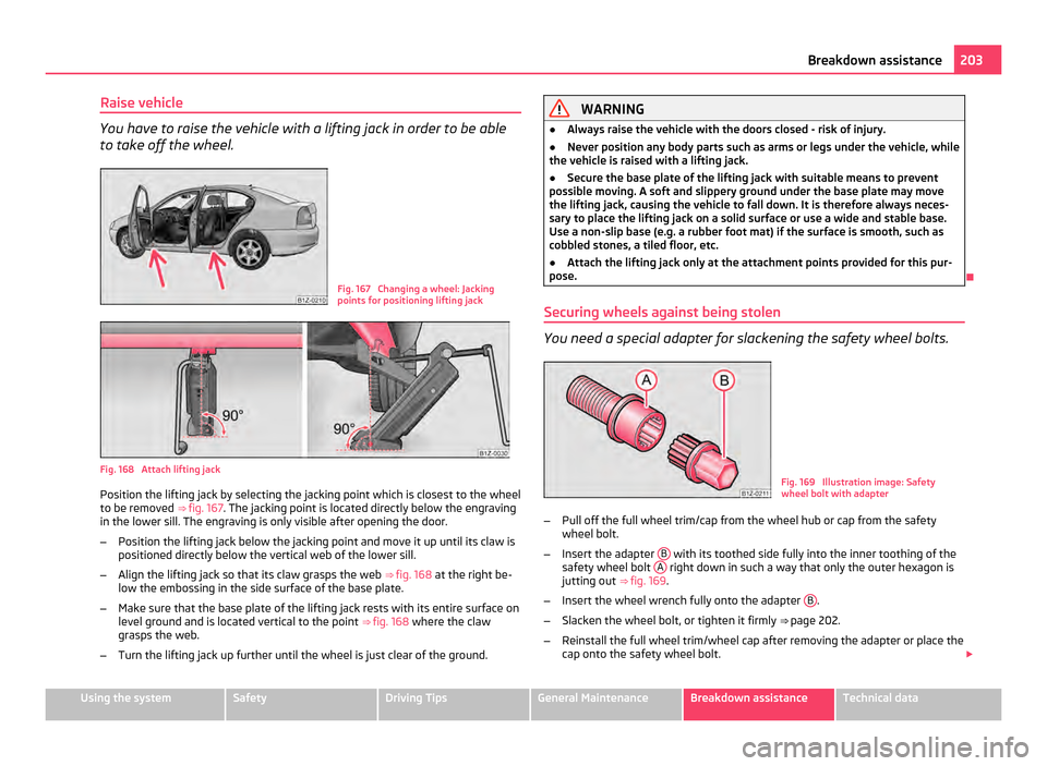
Wheel bolts with caps Fig. 164 Removing the cap.
Pulling off
– Push the plastic clip sufficiently far onto the cap until the inner catches of the
clip are positioned at the collar of the cap and detach the cap ⇒ fig. 164 .
Install
– Push the caps fully onto the wheel bolts.
The caps are located in the well of the luggage compartment. 201
Breakdown assistance Using the system Safety Driving Tips General Maintenance Breakdown assistance Technical data
Page 205 of 248
Raise vehicle
You have to raise the vehicle with a lifting jack in order to be able
to take off the wheel.
Fig. 167 Changing a wheel: Jacking
points for positioning lifting jack
Fig. 168 Attach lifting jack
Position the lifting jack by selecting the jacking point which is closest to the wheel
to be removed
⇒ fig. 167 . The jacking point is located directly below the engraving
in the lower sill. The engraving is only visible after opening the door.
– Position the lifting jack below the jacking point and move it up until its claw is
positioned directly below the vertical web of the lower sill.
– Align the lifting jack so that its claw grasps the web ⇒ fig. 168 at the right be-
low the embossing in the side surface of the base plate.
– Make sure that the base plate of the lifting jack rests with its entire surface on
level ground and is located vertical to the point ⇒
fig. 168 where the claw
grasps the web.
– Turn the lifting jack up further until the wheel is just clear of the ground. WARNING
● Always raise the vehicle with the doors closed - risk of injury.
● Never position any body parts such as arms or legs under the vehicle, while
the vehicle is raised with a lifting jack.
● Secure the base plate of the lifting jack with suitable means to prevent
possible moving. A soft and slippery ground under the base plate may move
the lifting jack, causing the vehicle to fall down. It is therefore always neces-
sary to place the lifting jack on a solid surface or use a wide and stable base.
Use a non-slip base (e.g. a rubber foot mat) if the
surface is smooth, such as
cobbled stones, a tiled floor, etc.
● Attach the lifting jack only at the attachment points provided for this pur-
pose.
Securing wheels against being stolen You need a special adapter for slackening the safety wheel bolts.
Fig. 169 Illustration image: Safety
wheel bolt with adapter
– Pull off the full wheel trim/cap from the wheel hub or cap from the safety
wheel bolt.
– Insert the adapter B with its toothed side fully into the inner toothing of the
safety wheel bolt A right down in such a way that only the outer hexagon is
jutting out ⇒ fig. 169 .
– Insert the wheel wrench fully onto the adapter B .
– Slacken the wheel bolt, or tighten it firmly ⇒ page 202.
– Reinstall the full wheel trim/wheel cap after removing the adapter or place the
cap onto the safety wheel bolt. £ 203
Breakdown assistance Using the system Safety Driving Tips General Maintenance Breakdown assistance Technical data
Page 207 of 248
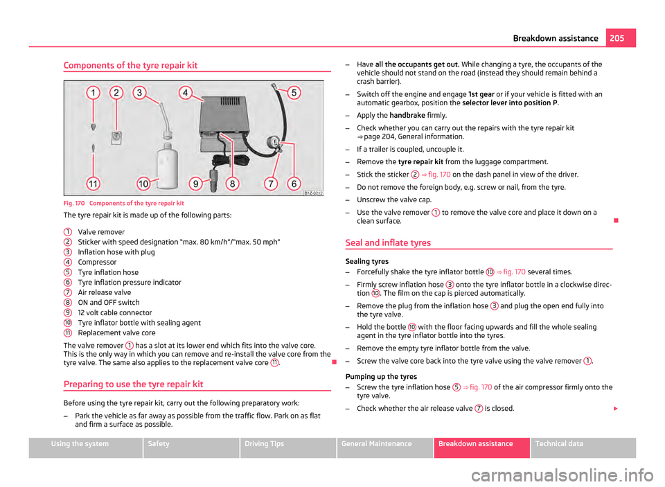
Components of the tyre repair kit
Fig. 170 Components of the tyre repair kit
The tyre repair kit is made up of the following parts:
Valve remover
Sticker with speed designation
“max. 80 km/h”/“max. 50 mph”
Inflation hose with plug
Compressor
Tyre inflation hose
Tyre inflation pressure indicator
Air release valve
ON and OFF switch
12 volt cable connector
Tyre inflator bottle with sealing agent
Replacement valve core
The valve remover 1 has a slot at its lower end which fits into the valve core.
This is the only way in which you can remove and re-install the valve core from the
tyre valve. The same also applies to the replacement valve core 11 .
Preparing to use the tyre repair kit Before using the tyre repair kit, carry out the following preparatory work:
–
Park the vehicle as far away as possible from the traffic flow. Park on as flat
and firm a surface as possible.
1 2
3
4
5
6
7
8
9
10
11 –
Have all the occupants get out. While changing a tyre, the occupants of the
vehicle should not stand on the road (instead they should remain behind a
crash barrier).
– Switch off the engine and engage 1st gear or if your vehicle is fitted with an
automatic gearbox, position the selector lever into position P .
– Apply the handbrake firmly.
– Check whether you can carry out the repairs with the tyre repair kit
⇒ page 204, General information
.
– If a trailer is coupled, uncouple it.
– Remove the tyre repair kit from the luggage compartment.
– Stick the sticker 2
⇒
fig. 170 on the dash panel in view of the driver.
– Do not remove the foreign body, e.g. screw or nail, from the tyre.
– Unscrew the valve cap.
– Use the valve remover 1 to remove the valve core and place it down on a
clean surface.
Seal and inflate tyres Sealing tyres
–
Forcefully shake the tyre inflator bottle 10
⇒ fig. 170 several times.
– Firmly screw inflation hose 3 onto the tyre inflator bottle in a clockwise direc-
tion 10 . The film on the cap is pierced automatically.
– Remove the plug from the inflation hose 3 and plug the open end fully into
the tyre valve.
– Hold the bottle 10 with the floor facing upwards and fill the whole sealing
agent in the tyre inflator bottle into the tyres.
– Remove the empty tyre inflator bottle from the valve.
– Screw the valve core back into the tyre valve using the valve remover 1 .
Pumping up the tyres
– Screw the tyre inflation hose 5
⇒
fig. 170 of the air compressor firmly onto the
tyre valve.
– Check whether the air release valve 7 is closed.
£ 205
Breakdown assistance Using the system Safety Driving Tips General Maintenance Breakdown assistance Technical data
Page 209 of 248
WARNING
● A discharged battery may already freeze at temperatures just below 0 °C.
In case of frozen battery carry out no jump-starting - risk of explosion!
● Please pay attention to the warning instructions relating to working in the
engine compartment ⇒ page 181, Working in the engine compartment
.Note
● There must not be any contact between the two vehicles otherwise current
may flow as soon as the negative terminals are connected.
● The discharged battery must be properly connected to the system of the vehi-
cle.
● Switch off any mobile phone, pay attention to the instructions for use of the
mobile phone in such a situation.
● We recommend you buy jump-start cables from a car battery specialist.
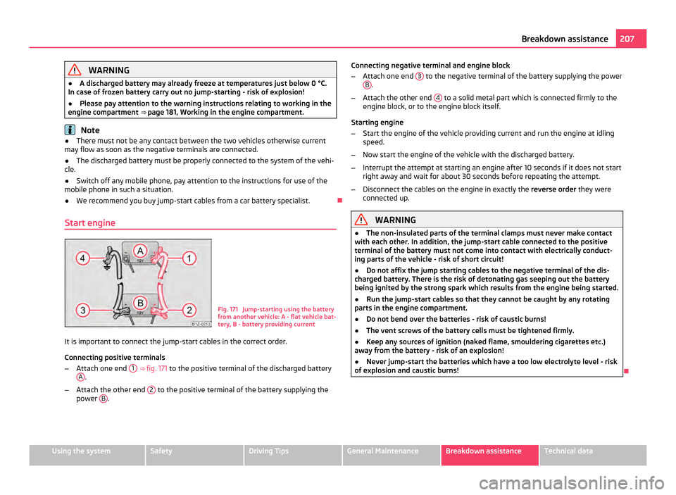
Start engine Fig. 171 Jump-starting using the battery
from another vehicle: A - flat vehicle bat-
tery, B - battery providing current
It is important to connect the jump-start cables in the correct order.
Connecting positive terminals
– Attach one end 1
⇒
fig. 171 to the positive terminal of the discharged battery
A .
– Attach the other end 2 to the positive terminal of the battery supplying the
power B . Connecting negative terminal and engine block
– Attach one end 3 to the negative terminal of the battery supplying the power
B .
– Attach the other end 4 to a solid metal part which is connected firmly to the
engine block, or to the engine block itself.
Starting engine
– Start the engine of the vehicle providing current and run the engine at idling
speed.
– Now start the engine of the vehicle with the discharged battery.
– Interrupt the attempt at starting an engine after 10 seconds if it does not start
right away and wait for about 30 seconds before repeating the attempt.
– Disconnect the cables on the engine in exactly the reverse order they were
connected up. WARNING
● The non-insulated parts of the terminal clamps must never make contact
with each other. In addition, the jump-start cable connected to the positive
terminal of the battery must not come into contact with electrically conduct-
ing parts of the vehicle - risk of short circuit!
● Do not affix the jump starting cables to the negative terminal of the dis-
charged battery. There is the risk of detonating gas seeping out the battery
being ignited by the strong spark which results from the engine being started.
● Run the jump-start cables so that they cannot be caught by any rotating
parts in the engine compartment.
● Do not bend over the batteries - risk of caustic burns!
● The vent screws of the battery cells must be tightened firmly.
● Keep any sources of ignition (naked flame, smouldering cigarettes etc.)
away from the battery - risk of an explosion!
● Never jump-start the batteries which have a too low electrolyte level - risk
of explosion and caustic burns! 207
Breakdown assistance Using the system Safety Driving Tips General Maintenance Breakdown assistance Technical data
Page 211 of 248
Note
● We recommend a tow rope from the range of ŠKODA Original Accessories that
you can purchase from an authorised ŠKODA Service Partner.
● Towing another vehicle requires a certain amount of practice. Both drivers
should be familiar with the particular points about towing a vehicle. Unskilled driv-
ers should not attempt to tow in another vehicle or to be towed in.
● When towing, respect the national legal provisions, especially those which re-
late to the identification of the towing vehicle and the vehicle being towed.
● The tow rope must not be twisted as it may in certain circumstances result in
the front towing eye being unscrewed out of your vehicle.
Front towing eye The towing eye is stored in the box of the vehicle tool kit.
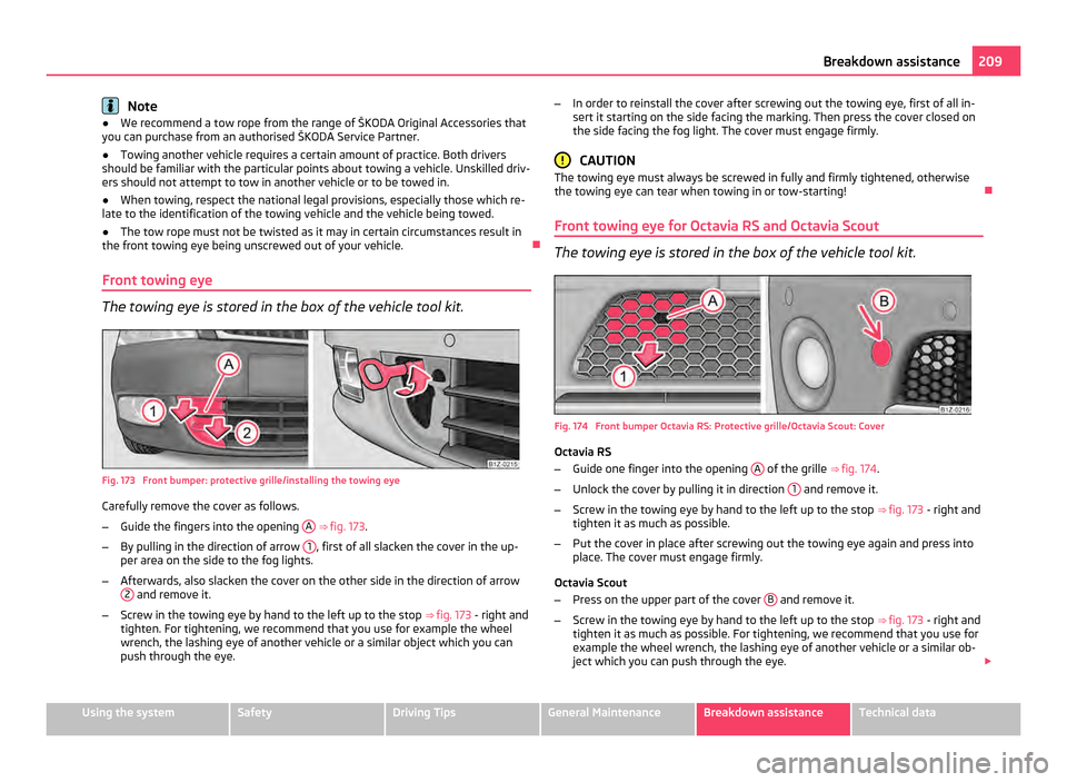
Fig. 173 Front bumper: protective grille/installing the towing eye
Carefully remove the cover as follows.
–
Guide the fingers into the opening A
⇒
fig. 173.
– By pulling in the direction of arrow 1 , first of all slacken the cover in the up-
per area on the side to the fog lights.
– Afterwards, also slacken the cover on the other side in the direction of arrow
2 and remove it.
– Screw in the towing eye by hand to the left up to the stop ⇒ fig. 173 - right and
tighten. For tightening, we recommend that you use for example the wheel
wrench, the lashing eye of another vehicle or a similar object which you can
push through the eye. –
In order to reinstall the cover after screwing out the towing eye, first of all in-
sert it starting on the side facing the marking. Then press the cover closed on
the side facing the fog light. The cover must engage firmly. CAUTION
The towing eye must always be screwed in fully and firmly tightened, otherwise
the towing eye can tear when towing in or tow-starting!
Front towing eye for Octavia RS and Octavia Scout The towing eye is stored in the box of the vehicle tool kit.
Fig. 174 Front bumper Octavia RS: Protective grille/Octavia Scout: Cover
Octavia RS
–
Guide one finger into the opening A of the grille
⇒ fig. 174 .
– Unlock the cover by pulling it in direction 1 and remove it.
– Screw in the towing eye by hand to the left up to the stop ⇒ fig. 173 - right and
tighten it as much as possible.
– Put the cover in place after screwing out the towing eye again and press into
place. The cover must engage firmly.
Octavia Scout
– Press on the upper part of the cover B and remove it.
– Screw in the towing eye by hand to the left up to the stop ⇒ fig. 173 - right and
tighten it as much as possible. For tightening, we recommend that you use for
example the wheel wrench, the lashing eye of another vehicle or a similar ob-
ject which you can push through the eye. £ 209
Breakdown assistance Using the system Safety Driving Tips General Maintenance Breakdown assistance Technical data
Page 213 of 248
Fuses and light bulbs
Electric fuses Replacing fuses in the dash panel Defect fuses must be replaced.
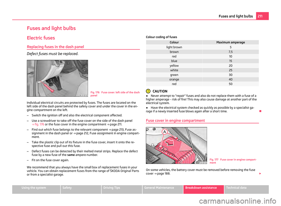
Fig. 176 Fuse cover: left side of the dash
panel
Individual electrical circuits are protected by fuses. The fuses are located on the
left side of the dash panel behind the safety cover and under the cover in the en-
gine compartment on the left.
– Switch the ignition off and also the electrical component affected.
– Use a screwdriver to take off the fuse cover on the side of the dash panel
⇒ fig. 176 or the fuse cover in the engine compartment ⇒ page 211.
– Find out which fuse belongs to the relevant component ⇒ page 213, Fuse as-
signment in the dash panel or ⇒ page 212, Fuse assignment in engine compart-
ment.
– Take the plastic clip out of its fixture in the fuse cover, insert it onto the re-
spective fuse and pull out this fuse.
– Defect fuses can be detected by their melted metal strips. Replace the defect
fuse by a new fuse of the same ampere number.
– Fit on the fuse cover again.
We recommend that you always have the small box of replacement fuses in your
vehicle. You can obtain replacement fuses from the range of
ŠKODA Original Parts
or from a specialist garage. Colour coding of fuses Colour Maximum amperage
light brown 5
brown 7,5
red 10
blue 15
yellow 20
white 25
green 30
orange 40
red 50
CAUTION
● Never attempt to
“repair” fuses and also do not replace them with a fuse of a
higher amperage - risk of fire! This may also cause damage at another part of the
electrical system.
● Have the electrical system checked as quickly as possible by a specialist ga-
rage if a newly inserted fuse blows again after a short time.
Fuse cover in engine compartment Fig. 177 Fuse cover in engine compart-
ment
On some vehicles, the battery cover must be removed before removing the fuse
cover ⇒ page 188
. £ 211
Fuses and light bulbs Using the system Safety Driving Tips General Maintenance Breakdown assistance Technical data
Page 215 of 248
Fuse assignment in the dash panel
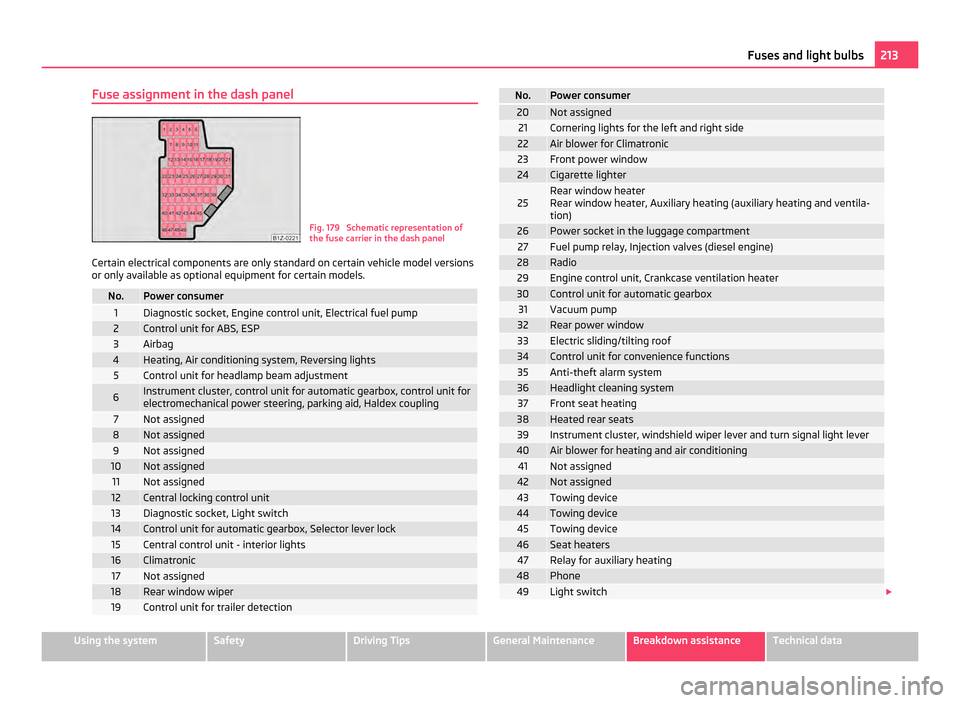
Fig. 179 Schematic representation of
the fuse carrier in the dash panel
Certain electrical components are only standard on certain vehicle model versions
or only available as optional equipment for certain models. No. Power consumer
1 Diagnostic socket, Engine control unit, Electrical fuel pump
2 Control unit for ABS, ESP
3 Airbag
4 Heating, Air conditioning system, Reversing lights
5 Control unit for headlamp beam adjustment
6 Instrument cluster, control unit for automatic gearbox, control unit for
electromechanical power steering, parking aid, Haldex coupling 7 Not assigned
8 Not assigned
9 Not assigned
10 Not assigned
11 Not assigned
12 Central locking control unit
13 Diagnostic socket, Light switch
14 Control unit for automatic gearbox, Selector lever lock
15 Central control unit - interior lights
16 Climatronic
17 Not assigned
18 Rear window wiper
19 Control unit for trailer detection No. Power consumer
20 Not assigned
21 Cornering lights for the left and right side
22 Air blower for Climatronic
23 Front power window
24 Cigarette lighter
25 Rear window heater
Rear window heater, Auxiliary heating (auxiliary heating and ventila-
tion)
26 Power socket in the luggage compartment
27 Fuel pump relay, Injection valves (diesel engine)
28 Radio
29 Engine control unit, Crankcase ventilation heater
30 Control unit for automatic gearbox
31 Vacuum pump
32 Rear power window
33 Electric sliding/tilting roof
34 Control unit for convenience functions
35 Anti-theft alarm system
36 Headlight cleaning system
37 Front seat heating
38 Heated rear seats
39 Instrument cluster, windshield wiper lever and turn signal light lever
40 Air blower for heating and air conditioning
41 Not assigned
42 Not assigned
43 Towing device
44 Towing device
45 Towing device
46 Seat heaters
47 Relay for auxiliary heating
48 Phone
49 Light switch
£ 213
Fuses and light bulbs Using the system Safety Driving Tips General Maintenance Breakdown assistance Technical data
Page 217 of 248
WARNING
● Bulbs H7 and H1 are pressurised and may burst when changing the bulb -
risk of injury!
● It is recommended to wear gloves and safety glasses when changing a
bulb.
● Gas discharge bulbs (xenon bulbs) operate with a high voltage, professio-
nal knowledge is required - danger to life! CAUTION
Do not take hold of the glass bulb with naked fingers (even the smallest amount
of dirt reduces the working life of the light bulb). Use a clean cloth, serviette or
something similar. Note
This Owner's Manual only describes the replacement of bulbs where it is assumed
that no major complications will arise. Other light bulbs should be changed by your
specialist garage.
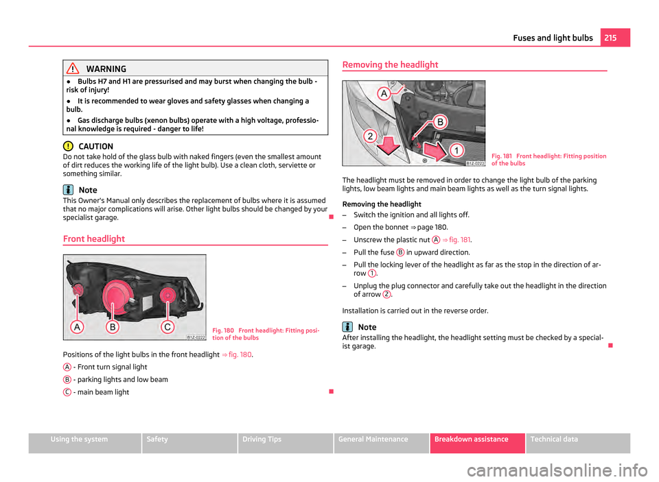
Front headlight Fig. 180 Front headlight: Fitting posi-
tion of the bulbs
Positions of the light bulbs in the front headlight ⇒ fig. 180 .
A - Front turn signal light
B - parking lights and low beam
C - main beam light
Removing the headlight
Fig. 181 Front headlight: Fitting position
of the bulbs
The headlight must be removed in order to change the light bulb of the parking
lights, low beam lights and main beam lights as well as the turn signal lights.
Removing the headlight
– Switch the ignition and all lights off.
– Open the bonnet ⇒ page 180 .
– Unscrew the plastic nut A
⇒ fig. 181 .
– Pull the fuse B in upward direction.
– Pull the locking lever of the headlight as far as the stop in the direction of ar-
row 1 .
– Unplug the plug connector and carefully take out the headlight in the direction
of arrow 2 .
Installation is carried out in the reverse order. Note
After installing the headlight, the headlight setting must be checked by a special-
ist garage. 215
Fuses and light bulbs Using the system Safety Driving Tips General Maintenance Breakdown assistance Technical data