trailer SKODA OCTAVIA 2011 2.G / (1Z) Owner's Manual
[x] Cancel search | Manufacturer: SKODA, Model Year: 2011, Model line: OCTAVIA, Model: SKODA OCTAVIA 2011 2.G / (1Z)Pages: 248, PDF Size: 3.79 MB
Page 6 of 248
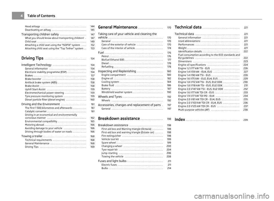
Head airbags . . . . . . . . . . . . . . . . . . . . . . . . . . . . . . . . . . . . . . 144
Deactivating an airbag . . . . . . . . . . . . . . . . . . . . . . . . . . . . . 145
Transporting children safely . . . . . . . . . . . . . . . . . . . . . . 147
What you should know about transporting children! . 147
Child seat . . . . . . . . . . . . . . . . . . . . . . . . . . . . . . . . . . . . . . . . . 149
Attaching a child seat using the “ISOFIX” system . . . . 152
Attaching child seat using the “Top Tether” system . . 153
Driving Tips . . . . . . . . . . . . . . . . . . . . . . . . . . . . . . . . . . . 154
Intelligent Technology . . . . . . . . . . . . . . . . . . . . . . . . . . . . 154
General information . . . . . . . . . . . . . . . . . . . . . . . . . . . . . . . 154
Electronic stability programme (ESP) . . . . . . . . . . . . . . . . 154
Brakes . . . . . . . . . . . . . . . . . . . . . . . . . . . . . . . . . . . . . . . . . . . . 157
Brake booster . . . . . . . . . . . . . . . . . . . . . . . . . . . . . . . . . . . . . 158
Antilock brake system (ABS) . . . . . . . . . . . . . . . . . . . . . . . . 158
Brake Assist . . . . . . . . . . . . . . . . . . . . . . . . . . . . . . . . . . . . . . . 158
Uphill Start Assist . . . . . . . . . . . . . . . . . . . . . . . . . . . . . . . . . 159
Electromechanical power steering . . . . . . . . . . . . . . . . . . 159
Tyre pressure monitoring system . . . . . . . . . . . . . . . . . . . 159
Diesel particle filter (diesel engine) . . . . . . . . . . . . . . . . . 160
Driving and the Environment . . . . . . . . . . . . . . . . . . . . . 161
The first 1 500 kilometres and afterwards . . . . . . . . . . . 161
Catalytic converter . . . . . . . . . . . . . . . . . . . . . . . . . . . . . . . . . 161
Driving in an economical and environmentally
conscious manner . . . . . . . . . . . . . . . . . . . . . . . . . . . . . . . . . 162
Environmental compatibility . . . . . . . . . . . . . . . . . . . . . . . . 165
Motoring abroad . . . . . . . . . . . . . . . . . . . . . . . . . . . . . . . . . . . 166
Avoiding damage to your vehicle . . . . . . . . . . . . . . . . . . . 166
Driving through bodies of water on roads . . . . . . . . . . . 166
Towing a trailer . . . . . . . . . . . . . . . . . . . . . . . . . . . . . . . . . . . . 168
Technical requirements . . . . . . . . . . . . . . . . . . . . . . . . . . . . 168
General Maintenance . . . . . . . . . . . . . . . . . . . . . . . . . . . . . . 168
Driving Tips . . . . . . . . . . . . . . . . . . . . . . . . . . . . . . . . . . . . . . . 169 General Maintenance
. . . . . . . . . . . . . . . . . . . . . 170
Taking care of your vehicle and cleaning the
vehicle . . . . . . . . . . . . . . . . . . . . . . . . . . . . . . . . . . . . . . . . . . . . . . 170
General . . . . . . . . . . . . . . . . . . . . . . . . . . . . . . . . . . . . . . . . . . . 170
Care of the exterior of vehicle . . . . . . . . . . . . . . . . . . . . . . 170
Care of the interior of vehicle . . . . . . . . . . . . . . . . . . . . . . . 174
Fuel . . . . . . . . . . . . . . . . . . . . . . . . . . . . . . . . . . . . . . . . . . . . . . . . . 176
Petrol . . . . . . . . . . . . . . . . . . . . . . . . . . . . . . . . . . . . . . . . . . . . . 176
Biofuel Ethanol E85 . . . . . . . . . . . . . . . . . . . . . . . . . . . . . . . . 177
Diesel . . . . . . . . . . . . . . . . . . . . . . . . . . . . . . . . . . . . . . . . . . . . . 178
Refuelling . . . . . . . . . . . . . . . . . . . . . . . . . . . . . . . . . . . . . . . . . 178
Inspecting and Replenishing . . . . . . . . . . . . . . . . . . . . . . 180
Engine compartment . . . . . . . . . . . . . . . . . . . . . . . . . . . . . . 180
Engine oil . . . . . . . . . . . . . . . . . . . . . . . . . . . . . . . . . . . . . . . . . 182
Cooling system . . . . . . . . . . . . . . . . . . . . . . . . . . . . . . . . . . . . 184
Brake fluid . . . . . . . . . . . . . . . . . . . . . . . . . . . . . . . . . . . . . . . . 186
Battery . . . . . . . . . . . . . . . . . . . . . . . . . . . . . . . . . . . . . . . . . . . 187
Windshield washer system . . . . . . . . . . . . . . . . . . . . . . . . . 190
Wheels and Tyres . . . . . . . . . . . . . . . . . . . . . . . . . . . . . . . . . . 192
Wheels . . . . . . . . . . . . . . . . . . . . . . . . . . . . . . . . . . . . . . . . . . . 192
Accessories, changes and replacement of parts . 197
General . . . . . . . . . . . . . . . . . . . . . . . . . . . . . . . . . . . . . . . . . . . 197
Breakdown assistance . . . . . . . . . . . . . . . . . . . 198
Breakdown assistance . . . . . . . . . . . . . . . . . . . . . . . . . . . . 198
First-aid box and Warning triangle (Octavia) . . . . . . . . . 198
First-aid box and warning triangle (Estate car) . . . . . . . 198
Fire extinguisher . . . . . . . . . . . . . . . . . . . . . . . . . . . . . . . . . . 198
Vehicle tool kit . . . . . . . . . . . . . . . . . . . . . . . . . . . . . . . . . . . . 199
Spare wheel . . . . . . . . . . . . . . . . . . . . . . . . . . . . . . . . . . . . . . . 199
Changing a wheel . . . . . . . . . . . . . . . . . . . . . . . . . . . . . . . . . 200
Tyre repair kit . . . . . . . . . . . . . . . . . . . . . . . . . . . . . . . . . . . . . 204
Jump-starting . . . . . . . . . . . . . . . . . . . . . . . . . . . . . . . . . . . . . 206
Towing the vehicle . . . . . . . . . . . . . . . . . . . . . . . . . . . . . . . . 208
Fuses and light bulbs . . . . . . . . . . . . . . . . . . . . . . . . . . . . . . 211
Electric fuses . . . . . . . . . . . . . . . . . . . . . . . . . . . . . . . . . . . . . . 211
Bulbs . . . . . . . . . . . . . . . . . . . . . . . . . . . . . . . . . . . . . . . . . . . . . 214 Technical data
. . . . . . . . . . . . . . . . . . . . . . . . . . . . . . . 221
Technical data . . . . . . . . . . . . . . . . . . . . . . . . . . . . . . . . . . . . . 221
General information . . . . . . . . . . . . . . . . . . . . . . . . . . . . . . . 221
Used abbreviations . . . . . . . . . . . . . . . . . . . . . . . . . . . . . . . . 221
Performances . . . . . . . . . . . . . . . . . . . . . . . . . . . . . . . . . . . . . 221
Weight . . . . . . . . . . . . . . . . . . . . . . . . . . . . . . . . . . . . . . . . . . . . 221
Identification details . . . . . . . . . . . . . . . . . . . . . . . . . . . . . . . 222
Fuel consumption according to the ECE standards and
EU guidelines
. . . . . . . . . . . . . . . . . . . . . . . . . . . . . . . . . . . . . 222
Dimensions . . . . . . . . . . . . . . . . . . . . . . . . . . . . . . . . . . . . . . . 223
Engine oil specifications . . . . . . . . . . . . . . . . . . . . . . . . . . . 224
Engine 1.2 l/77 kW TSI - EU5 . . . . . . . . . . . . . . . . . . . . . . . . 226
Engine 1.4 l/59 kW - EU4, EU5 . . . . . . . . . . . . . . . . . . . . . . 227
Engine 1.4 l/90 kW TSI - EU5 . . . . . . . . . . . . . . . . . . . . . . . . 228
Engine 1.6 l/75 kW - EU2, EU4, EU5 . . . . . . . . . . . . . . . . . . 229
Engine 1.8 l/112 kW TSI - EU5, EU2 DDK . . . . . . . . . . . . . . 230
Engine 1.8 l/118 kW TSI - EU5, EU2 DDK . . . . . . . . . . . . . . 231
Engine 2.0 l/147 kW TSI - EU5, EU2 DDK . . . . . . . . . . . . . 232
Engine 1.6 l/77 kW TDI CR - EU5 . . . . . . . . . . . . . . . . . . . . . 233
Engine 1.9 l/77 kW TDI PD - EU4 . . . . . . . . . . . . . . . . . . . . 234
Engine 2.0 l/81 kW TDI CR - EU4, EU5 . . . . . . . . . . . . . . . 235
Engine 2.0 l/103 kW TDI CR - EU4, EU5 . . . . . . . . . . . . . . 236
Engine 2.0 l/125 kW TDI CR - EU5 . . . . . . . . . . . . . . . . . . . 237
Multi-purpose vehicles (AF) . . . . . . . . . . . . . . . . . . . . . . . . 238
Index . . . . . . . . . . . . . . . . . . . . . . . . . . . . . . . . . . . . . . . . . . . . . 2394
Table of Contents
Page 25 of 248
Turn signal lights
Either the left
or right indicator light flashes depending on the position of the
turn signal lever.
The indicator light flashes at twice its normal rate if a turn signal light fails. This
does not apply when towing a trailer.
Switching off the hazard warning light system is switched on will cause all of the
turn signal lights as well as both indicator lights to flash.
Further information about the turn signal system ⇒
page 50.
Fog lights The warning light
comes on when the fog lights are operating ⇒
page 47.
Main beam The indicator light
comes on when the main beam is selected or also when the
headlight flasher is operated.
Further information about the main beam ⇒
page 50.
Low beam The indicator light
comes on when low beam is selected ⇒ page 44.
Rear fog light The warning light
comes on when the rear fog lights are operating ⇒
page 48.
Cruise control The warning light
lights up, when operating the speed regulating system. Bulb failure
The warning light
comes on if a bulb is faulty:
● up to 2 seconds after the ignition is switched on,
● when switching on the defective light bulb.
The following text e.g will be displayed in the information display: Check front right dipped beam! (Check front right dipped beam!)
Diesel particle filter (diesel engine) If the warning light
comes on, this means that soot has accumulated in the
diesel particle filter because of the frequent short distances.
In order to clean the diesel particulate filter, the vehicle should be driven at an
even speed of at least 60 km/h at engine speeds of 1
800 - 2 500 rpm for at least
15 minutes or until the warning light goes out with the 4th or 5th gear engaged
(automatic gearbox: position S) when the traffic situation permits it. This increa-
ses the exhaust temperature and the soot deposited in the diesel particle filter is
burnt.
Always pay attention to the valid speed limits ⇒ .
The warning light goes out after the successful cleaning of the diesel particle
filter.
If the filter is not properly cleaned, the warning light does not go out and the
warning light begins to flash. The following is displayed in the information dis-
play: Diesel-particle filter: Owner's manual! appears. Afterwards the engine con-
trol unit shifts the engine into the emergency mode, which only has a reduced
power output. After switching the ignition off and on again the warning light
comes on.
Have the vehicle inspected without delay by your specialist garage. WARNING
● If you do not pay attention to the warning light coming on and the corre-
sponding descriptions and warning notes, this may result in injuries or major
vehicle damage.
● Always adjust your speed to suit weather, road, region and traffic condi-
tions. The route indicated by the warning light must not tempt you to disre-
gard the national regulations for road traffic. £ 23
Instruments and warning lights Using the system Safety Driving Tips General Maintenance Breakdown assistance Technical data
Page 50 of 248
The warning light
lights up in the instrument cluster when the fog lights are
switched on ⇒
page 21.
Fog lights with the function “CORNER” The fog lights with the function “CORNER” are designed for a bet-
ter illumination of the surrounding area near the vehicle when
corning, parking etc.
The fog lights with the function
“CORNER” are adjusted according to the steering
angle or after switching on the turn signal light 1)
in the following circumstances:
● the vehicle is stationary and the engine is running or it moves with a speed of
maximum 40 km/h;
● the daylight driving lights are not switched on;
● the low beam is switched on or the light switch is in the position
and the
intensity of the ambient light causes the low beam to be switched on;
● the fog lights are not switched on;
● no reverse gear is engaged. Note
If you engage the reverse gear during the active function “CORNER”, both fog
lights illuminate.
Rear fog light Switching on the rear fog light
–
First of all turn the light switch into position or ⇒
fig. 26 .
– Pull the switch into position 2 .
The warning light
lights up in the instrument cluster when the rear fog light is
switched on ⇒ page 21.
Only the rear fog light of the trailer lights up if the vehicle has a factory-fitted
towing device or a towing device from ŠKODA original accessories and when you
are towing a trailer which is fitted with the rear fog light. The rear fog light is located in the rear light array on the driver's side. CAUTION
The rear fog light should only be switched on if visibility is particularly poor (con-
form with any varying legal provisions) to avoid dazzling vehicles behind your ve-
hicle.
Instrument lighting You can adjust the brightness of the instrument lighting.
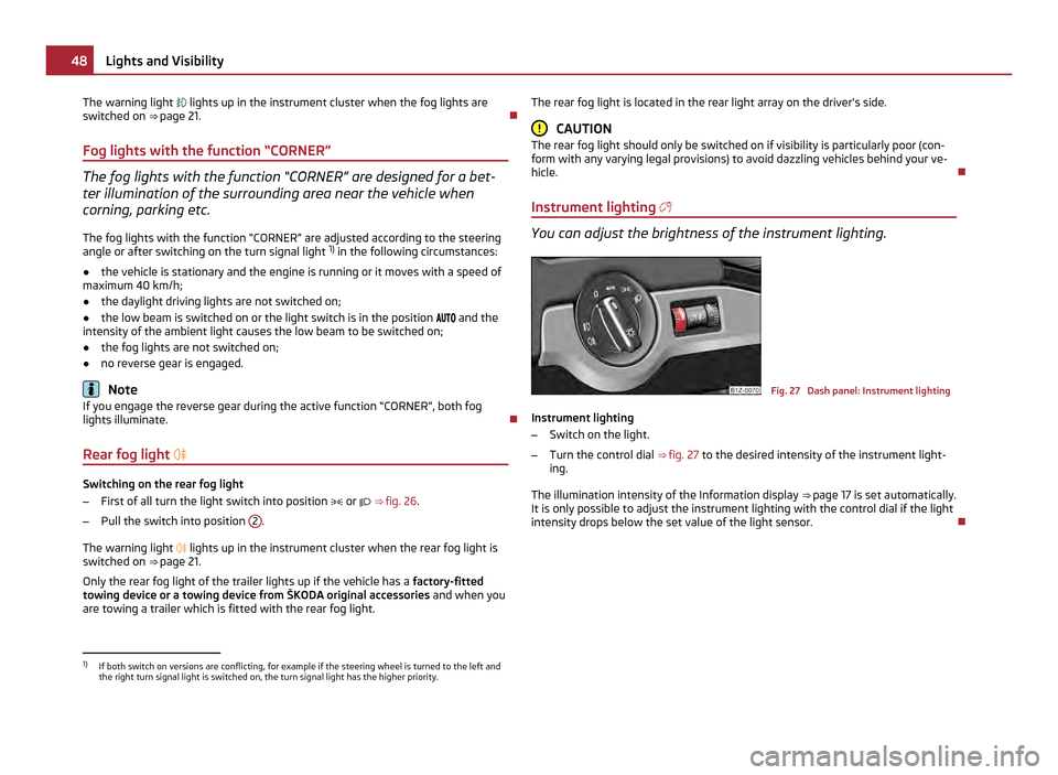
Fig. 27 Dash panel: Instrument lighting
Instrument lighting
– Switch on the light.
– Turn the control dial ⇒
fig. 27 to the desired intensity of the instrument light-
ing.
The illumination intensity of the Information display ⇒ page 17 is set automatically.
It is only possible to adjust the instrument lighting with the control dial if the light
intensity drops below the set value of the light sensor. 1)
If both switch on versions are conflicting, for example if the steering wheel is turned to the left and
the right turn signal light is switched on, the turn signal light has the higher priority. 48
Lights and Visibility
Page 104 of 248
The handbrake warning light
lights up when the handbrake is applied, provided
the ignition is on.
A warning signal sounds and the following text appears in the Information display
if you have inadvertently driven off with the handbrake applied:
Release parking brake! (Release parking brake!)
The handbrake warning is activated if you drive at a speed of more than 6 km/h
for more than 3 seconds. WARNING
● Please note that the handbrake must be fully released. A handbrake which
is only partially released can result in the rear brakes overheating which will
have a negative effect on the operation of the brake system - risk of accident!
In addition this can result in premature wear of the rear brake pads.
● Never leave children unattended in the vehicle. The children might, for ex-
ample, release the handbrake or take the vehicle out of gear. The vehicle
might then move off - risk of accident! CAUTION
After the car has come to a stop, always first of all apply the handbrake firmly be-
fore then additionally engaging a gear (manual gearbox) or moving the selector
lever into position P (automatic gearbox).
Rear parking aid The parking aid provides a warning of obstacles behind the vehicle.
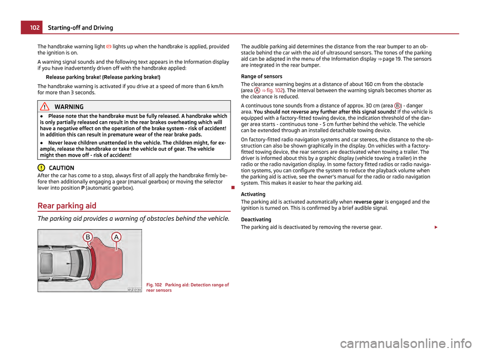
Fig. 102 Parking aid: Detection range of
rear sensorsThe audible parking aid determines the distance from the rear bumper to an ob-
stacle behind the car with the aid of ultrasound sensors. The tones of the parking
aid can be adapted in the menu of the Information display
⇒
page 19. The sensors
are integrated in the rear bumper.
Range of sensors
The clearance warning begins at a distance of about 160 cm from the obstacle
(area A ⇒
fig. 102). The interval between the warning signals becomes shorter as
the clearance is reduced.
A continuous tone sounds from a distance of approx. 30 cm (area B ) - danger
area. You should not reverse any further after this signal sounds! If the vehicle is
equipped with a factory-fitted towing device, the indication threshold of the dan-
ger area starts -
continuous tone - 5 cm further behind the vehicle. The vehicle
can be extended through an installed detachable towing device.
On factory-fitted radio navigation systems and car stereos, the distance to the ob-
struction can also be shown graphically in the display. On vehicles with a factory-
fitted towing device, the rear sensors are deactivated when towing a trailer. The
driver is informed about this by a graphic display (vehicle towing a trailer) in the
radio or the radio navigation display. In some factory fitted radios or radio naviga-
tion systems, you can configure the system to reduce the playback volume when
the parking aid is active, see the owner's manual for the radio or radio navigation
system. This makes it easier to hear the parking aid.
Activating
The parking aid is activated automatically when reverse gear is engaged and the
ignition is turned on. This is confirmed by a brief audible signal.
Deactivating
The parking aid is deactivated by removing the reverse gear. £102
Starting-off and Driving
Page 105 of 248

WARNING
● The parking aid is not a substitute for the driver paying proper attention
and it is always the driver's responsibility to take care when parking the vehi-
cle or carrying out similar manoeuvres.
● You should therefore satisfy yourself, before reversing, that there is no
small obstacle, such as a rock, thin post, trailer drawbar etc., behind your vehi-
cle. Such an obstacle might not be within the range detected by the sensors.
● Under certain circumstances, surfaces of certain objects and types of
clothing cannot reflect the signal of the parking aid. Thus, these objects or
people who wear such clothing are not recognised by the sensors of the park-
ing aid. Note
● The parking aid does not operate if you are towing a trailer (applies to models
which feature a factory-fitted towing device).
● If a warning signal sounds for about 3 seconds after switching the ignition on
and engaging reverse gear, and there is no obstacle close to your car, this indi-
cates a system fault. Have the fault rectified by a specialist workshop.
● The sensors must be kept clean and free of ice to enable the parking aid to
operate properly.
Front and rear parking aid The parking aid provides a warning of obstacles in front and behind
the vehicle. Fig. 103 Activating the parking aid/detection range of the front sensors The audible parking aid determines the distance between the front or rear bump-
er and an obstacle with the aid of ultrasound sensors. The sensors are integrated
in the front and rear bumper. The signal tones for the front parking aid sound
higher as standard than for the rear parking aid. The tones of the parking aid can
be adapted in the menu of the Information display ⇒ page 19.
Range of sensors
The distance warning begins at a distance of about 120 cm from the obstacle in
front of the vehicle (area A ⇒
fig. 103) and about 160 cm from the obstacle behind
the vehicle (area A ⇒ fig. 102
). The interval between the warning signals becomes
shorter as the clearance is reduced.
A continuous tone sounds from a distance of approx. 30 cm (area B ) - danger
area. From this moment on do not continue driving! If the vehicle is equipped with
a factory-fitted towing device, the border of the danger area starts -
continuous
tone - 5 cm further away from the vehicle. The vehicle can be extended through
an installed detachable towing device.
On factory-fitted radio navigation systems and car stereos, the distance to the ob-
struction can also be shown graphically in the display. On vehicles with a factory-
fitted towing device, the rear sensors are deactivated when towing a trailer. The
driver is informed about this by a graphic display (vehicle towing a trailer) in the
radio or the radio navigation display. In some factory fitted radios or radio naviga-
tion systems, you can configure the system to reduce the playback volume when
the parking aid is active, see the owner's manual for the radio or radio navigation
system. This makes it easier to hear the parking aid.
Activating
The parking aid is activated when the reverse gear is engaged and the ignition is
switched on or by pressing the button ⇒ fig. 103 - left, the symbol lights up in
the button. The activation is confirmed by a brief acknowledgement signal.
Deactivating
The parking aid is deactivated after pressing the button
⇒
fig. 103 - left, or at a
speed of more than 10 km/h - the symbol in the button is no longer illuminated. £ 103
Starting-off and Driving Using the system Safety Driving Tips General Maintenance Breakdown assistance Technical data
Page 106 of 248
WARNING
● The parking aid is not a substitute for the driver paying proper attention
and it is always the driver's responsibility to take care when reversing the ve-
hicle or carrying out similar manoeuvres.
● You should therefore satisfy yourself, before reversing, that there is no
small obstacle, such as a rock, thin post, trailer drawbar etc., in front or behind
your vehicle. Such an obstacle might not be within the range detected by the
sensors.
● Under certain circumstances, surfaces of certain objects and types of
clothing cannot reflect the signal of the parking aid. Thus, these objects or
people who wear such clothing are not recognised by the sensors of the park-
ing aid. Note
● Only the front parking aid operates if you are towing a trailer (applies only to
models which feature a factory-fitted towing device).
● If a warning signal sounds for about 3 seconds after activating the system and
there is no obstacle close to your car, this indicates a system fault. The fault is
confirmed additionally when the symbol flashes in the button ⇒ fig. 103 - left.
Have the fault rectified by a specialist workshop.
● The sensors must be kept clean and free of ice to enable the parking aid to
operate properly.
● If the parking aid is activated and the selector lever of the automatic gearbox
is in the position P , warning signal indicates interruption (vehicle can no longer
move).
Cruise control system (CCS) Introduction The cruise control system (CCS) maintains a constant speed, more than 30 km/h
(20 mph), once it has been set, without you having to depress the accelerator
pedal. This is only possible within the range which is permitted by the power out-
put and braking power of the engine. The cruise control system makes it possible
- particularly on long journeys - for you to rest your
“accelerator foot”. WARNING
● For safety reasons, the cruise control system must not be used in dense
traffic or on unfavourable road surfaces (such as icy roads, slippery roads,
loose gravel) - risk of accident!
● In order to prevent unintentional use of the cruise control system, always
switch off the system after use. Note
● Models fitted with a manual gearbox: Always depress the clutch pedal if you
switch on the cruise control system when the gearbox is in Neutral! Otherwise the
engine can rev up unintentionally.
● The cruise control system is not able to maintain a constant speed when driv-
ing on steep downhill sections. The weight of the vehicle increases the speed at
which it travels. One should shift down in good time to a lower gear or slow the
vehicle down by applying the foot brake.
● It is not possible on vehicles fitted with an automatic gearbox to switch on the
cruise control system if the selector lever is in the position P, N or R.
Storing a speed Fig. 104 Operating lever: Rocker button
and switch of the cruise control system
The cruise control system is operated by means of the switch A
⇒ fig. 104 and
the rocker button B in the left lever of the multi-functional switch.
– Press the switch A into the position ON.
– After the desired speed has been reached, press the rocker button B into the
SET position. £104
Starting-off and Driving
Page 108 of 248
The function is automatically activated each time the ignition is switched on.
In the start-stop mode, the engine automatically switches to the vehicle's idle
phase, e.g. when stopped at traffic lights.
Information regarding the current state of the
“START-STOP” system is indicated
in the display of the instrument cluster.
Automatic engine shut down (stop phase)
– Stop the vehicle (where necessary, apply the handbrake).
– Take the vehicle out of gear.
– Take your foot off the clutch.
Automatic engine restart (start phase).
– Push down on the clutch.
Switching the
“START-STOP” system on and off
You can switch the “START STOP” system on/off by pressing the button ⇒ fig. 105.
When start-stop mode is deactivated, the warning light in the button lights up.
If the vehicle is in the stop phase when manually switching off the system, the en-
gine starts immediately.
The “START-STOP” system is very complex. Some of the procedures are hard to
check without servicing. The general conditions for the proper functioning of the
“START-STOP” system are listed in the following overview.
Conditions for the automatic engine shut down (stop phase) The gearshift lever is in Neutral.
The clutch pedal is not pressed!
The driver has fastened the seat belt.
The driver's door is closed.
The bonnet is closed.
The vehicle is at a standstill.
The factory-fitted towing device is not electrically connected to a trailer.
The engine is at operating temperature.
The charge state of the vehicle battery is sufficient.
The stationary vehicle is not on a steep slope or a steep downhill section.
The engine speed is less than 1200 1/min. The temperature of the vehicle battery is not too low or too high.
The pressure in the brake system is sufficient.
The difference between the outdoor- and the set temperature in the interior is
not too great.
The vehicle speed since the last time the engine was switched off was greater
than 3 km/h.
No cleaning of the diesel particle filter takes place
⇒ page 23 The front wheels are not turned excessively (the steering angle is less than 3/4
of a steering wheel revolution). Conditions for an automatic restart (start phase)
The clutch is pressed.
The max./min. temperature is set.
The Defrost function for the windscreen is switched on.
A high blower stage has been selected.
The “START STOP” button is pressed.
Conditions for an automatic restart without driver intervention
The vehicle moves at a speed of more than 3 km/h.
The difference between the outdoor- and the set temperature in the interior is
too great.
The charge state of the vehicle battery is not sufficient.
The pressure in the brake system is not sufficient.
Messages in the instrument cluster display (valid for vehicles without
Information display) ERROR: START STOP
Error in the START-STOP system
START STOP NOT POSSIBLE Automatic engine shut down is not
possible
START STOP ACTIVE Automatic engine shut down (stop
phase)
SWITCH OFF IGNITION
Switch off the ignition
START MANUALLY
Start the engine manually
£106
Starting-off and Driving
Page 112 of 248

Selector lever positions
Fig. 106 Selector lever/information display: Selector lever positions
The current selector lever position is indicated in the information display of the in-
strument cluster ⇒ fig. 106 - right. In the positions D and S the gear you have al-
ready engaged will be additionally displayed on the display.
P - Parklock
The driven wheels are locked mechanically in this position.
The Parklock must only be engaged when the vehicle is stationary ⇒ .
If you wish to move the selector lever into or out of this position, you must press
the Shiftlock button in the handle of the selector lever and at the same time de-
press the brake pedal.
If the battery is used, the selector lever cannot be moved out of the position P.
R - Reverse gear
Reverse gear must only be engaged when the vehicle is stationary and the engine
idling ⇒ .
The brake pedal must be depressed and at the same time the Shiftlock must be
pressed, if you wish to obtain the selector lever positions R, P or N.
When the ignition is switched on and the selector lever is in position R, the re-
verse lights will come on.
N - Neutral
The transmission is in Neutral in this position. The brake pedal must be depressed (if the lever is in its position for longer than 2
seconds) in order to move the selector lever out of the position
N into the position
D or R, with the ignition switched on, on a vehicle travelling at less than 5 km/
hour or on a stationary vehicle.
D - Position for driving forward
When the selector lever is in this position, the forward gears are shifted up and
down automatically in line with engine load, vehicle speed and the dynamic shift
programme.
You must depress the brake pedal if you wish to move into position D from N
when the vehicle is travelling at less than 5
km/hour or is stationary ⇒ .
Under certain circumstances (e.g. when driving in mountainous regions or when
towing a trailer) it may be beneficial to select the manual shift programme
⇒ page 112 for a short time in order to adapt the gearbox ratios manually to the
driving situations.
S - Position for sporty style of driving
Shifting up later into a higher gear makes it possible to fully exploit the power po-
tential of the engine. The gearbox also then shifts down at higher engine speeds
as in the position D .
The gearbox does not shift into the 6th gear in the position S, because the maxi-
mum speed is reached with the 5th gear 1)
.
The Shiftlock on the selector lever grip must be pressed when moving the selec-
tor lever out of the position D into the position S. WARNING
● Never move the selector lever into position
R or P when driving - risk of an
accident!
● When the engine is running and the vehicle is stationary, it is necessary to
hold the car with the brake pedal in all the positions of the selector lever (ex-
cept P and N) since the power transmission is never completely interrupted,
also not when the engine is idling - the vehicle creeps. £1)
Not valid for vehicles with automatic gearbox DSG. 110
Automatic gearbox
Page 161 of 248
The Brake Assist is able to help you achieve a shorter braking distance in emer-
gency situations by rapidly producing the pressure required in the brake system. It
fully exploits the attributes of the ABS. After you release the brake pedal, the
function of the Brake Assist is automatically switched off and the brakes operate
in the normal way.
The Brake Assist is part of the ESP system. If a fault occurs in the ESP, the Brake
Assist function is also not available. Further information on the ESP
⇒ page 154.WARNING
● The Brake Assist is also not able to overcome the physical limits of your car
in terms of the braking distance required.
● Adapt your speed to the conditions of the road surface and to the traffic
situation.
● The increased safety offered by the Brake Assist must not tempt you to
take a greater safety risk than otherwise.
Uphill Start Assist The uphill start assist makes it easier to start off on steep hills. The system assists
a start off by holding the brake pressure produced by the brake pedal actuation
for approx. 2 seconds after releasing the brake pedal. The driver can therefore
move his foot from the brake pedal to the accelerator pedal and start off on the
slope, without having to actuate the handbrake. The brake pressure drops gradu-
ally the more you operate the accelerator pedal. If the vehicle does not start off
within 2 seconds, it starts to roll back.
The uphill start assist is active as of a 5 % slope, if the driver door is closed. It is
always active on slopes when in forward or reverse start off. When driving down-
hill, it is inactive.
Electromechanical power steering The power steering enables you to steer the vehicle with less physical force.
With the electromechanical power steering, the steering assist is automatically
adapted to the speed and to the steering angle.
It is still possible to fully steer the vehicle if the power steering fails or if the en-
gine is not running (vehicle being towed in). The only difference is that greater
physical effort is required. If there is a fault in the power steering, the warning light
or lights up in the
instrument cluster ⇒
page 24. WARNING
Contact your specialist garage if the power steering is defective.
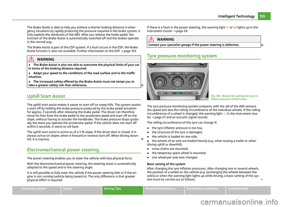
Tyre pressure monitoring system Fig. 140 Button for setting the tyre in-
flation pressure control value
The tyre pressure monitoring system compares with the aid of the ABS sensors
the speed and also the rolling circumference of the individual wheels. If the rolling
circumference of a wheel is changed, the warning light
in the instrument clus-
ter ⇒ page 27 and an acoustic signal sounds.
The rolling circumference of the tyre can change if:
● the tyre inflation pressure is too low,
● the structure of the tyre is damaged,
● the vehicle is loaded on one side,
● the wheels of an axle are loaded heavily (e.g. when towing a trailer or when
driving uphill or downhill),
● snow chains are mounted,
● the temporary spare wheel is mounted,
● one wheel per axle was changed.
Basic setting of the system
After changing the tyre inflation pressures, after changing one or several wheels,
the position of a wheel on the vehicle (e.g. exchanging the wheels between the
axles) or when the warning light lights up while driving, a basic setting of the sys-
tem must be carried out as follows. £ 159
Intelligent Technology Using the system Safety Driving Tips General Maintenance Breakdown assistance Technical data
Page 163 of 248
Driving and the Environment
The first 1 500 kilometres and afterwards
New engine The engine has to be run in during the first 1 500 kilometres.
Up to 1 000 kilometres
– Do not drive faster than 3/4 of the maximum speed of the gear in use, that is
3/4 of the maximum permissible engine speed.
– Do not use full throttle.
– Avoid high engine revolutions.
– Do not tow a trailer.
From 1 000 up to 1 500 kilometres
– Increase the power output of the engine gradually up to the full speed of the
gear engaged, that is up to the maximum permissible engine revolutions.
During the first operating hours the engine has higher internal friction than later
until all of the moving parts have harmonized. The driving style which you adopt
during the first approx.1 500 kilometres plays a decisive part in the success of run-
ning in your car.
You should not drive at unnecessarily high engine revolutions even after the run-
ning-in period is complete. The maximum permissible engine speed is marked by
the beginning of the red zone on the scale of the revolutions counter. Shift up in-
to the next higher gear on a vehicle fitted with manual gearbox before the red
zone is reached. During acceleration (depressing the accelerator) exceptionally
high engine speeds are automatically reduced, yet the engine is not protected
against too high engine speeds which are caused by incorrectly shifting down the
gears resulting in a sudden increase of the engine speeds above the permitted
maximum revolutions which can lead to engine damage.
For a vehicle fitted with a manual gearbox the converse situation also applies: Do
not drive at engine revolutions which are too low. Shift down as soon as the en-
gine is no longer running smoothly. CAUTION
All the speed and engine revolution figures apply only when the engine is at its
normal operating temperature. Never rev up an engine which is cold, neither when
the vehicle is stationary nor when driving in individual gears. For the sake of the environment
Not driving at unnecessarily high engine revolutions and shifting to a higher gear
as early as possible are ways to minimise fuel consumption and operating noise
levels and protects the environment.
New tyres New tyres have to be “run in” since they do not offer optimal grip at first. You
should take account of this fact for the first 500 kilometres and drive particularly
carefully.
New brake pads Allow for the fact that new brake pads do not achieve their full braking efficiency
until approximately 200 kilometres. New brake pads must be first “run in” before
they develop their optimal friction force. You can, however, compensate for this
slightly reduced braking force by increasing the pressure on the brake pedal.
This guideline also applies to any new brake pads installed at a future date.
During the running-in period, you should avoid excessive stresses on the brakes.
This includes, for example, violent braking, particularly from very high speeds, and
also when crossing mountain passes.
Catalytic converter Proper operation of the emission control system (catalytic convert-
er) is of major significance for driving your vehicle in an environ-
mentally conscious way.
Please refer to the following guidelines: £ 161
Driving and the Environment Using the system Safety Driving Tips General Maintenance Breakdown assistance Technical data