tow SKODA OCTAVIA 2012 2.G / (1Z) User Guide
[x] Cancel search | Manufacturer: SKODA, Model Year: 2012, Model line: OCTAVIA, Model: SKODA OCTAVIA 2012 2.G / (1Z)Pages: 222, PDF Size: 13.52 MB
Page 59 of 222
WARNING■Make sure that the mirror is not covered by ice, snow, mist or other objects.■Convex (curved outward) exterior mirrors increase the field of vision. They
do, however, make objects appear smaller in the mirror. These mirrors are
therefore only of limited use for estimating distances to the following vehi-
cles.■
Whenever possible use the interior mirror for estimating the distances to
the following vehicles.
■
Automatic dimming mirrors contain an electrolytic fluid which may leak
should the mirror glass break. The leaking electrolytic fluid can irritate the skin, eyes and breath apparatus. Immediately seek out fresh air and leave thevehicle. If this is not possible, open all windows and doors.
■
If you swallow electrolytic fluid, seek medical assistance immediately.
■
If your eyes or skin come into contact with the electrolytic fluid, immediately
wash the affected area for a few minutes long with a lot of water. Then con-
sult a doctor immediately.
■
The illuminated display of an external navigation unit can lead to operation-
al faults to the automatic dimming interior mirror- risk of accident.
CAUTION
Never mechanically fold in or fold back the exterior mirrors with the fold-in func-
tion by hand as this will damage the electric drive.
Note
■
Automatic mirror dimming operates only properly if the sun screen for the rear
window in the housing on the boot cover is not in use or the light striking the in- terior rear-view mirror is not affected by other objects.■
If the automatic interior mirror dimming is switched off, the exterior mirror dim-
ming is also switched off.
■
Do not touch the surface of the exterior mirrors if the exterior mirror heater is
switched on.
■
If the the electrical exterior mirror setting fails at any time, the two mirrors can
be adjusted by hand by pressing on the edge of the mirror surface.
■
Contact your ŠKODA specialist garage if there is a fault with the power setting
of the exterior mirrors.
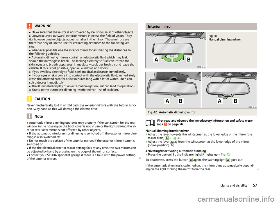
Interior mirrorFig. 41
Manual dimming mirror
Fig. 42
Automatic dimming mirror
First read and observe the introductory information and safety warn-
ings
on page 56.
Manual dimming interior mirror
›
Adjust the lever towards the windscreen at the lower edge of the mirror (the mirror dims)
A
» Fig. 41 .
›
Adjust the lever away from the windscreen at the lower edge of the mirror
(home position)
B
.
Activating/deactivating automatic dimming
›
Press the button
B
, the indicator light
A
lights up » Fig. 42.
To deactivate, press the button
B
again, the warning light
A
goes out.
If the automatic dimming is switched on, the mirror dims automatically depend-
ing on the light striking the mirror from the rear.
57Lights and visibility
Page 61 of 222
Seats and Stowage
Front seats
Introduction
This chapter contains information on the following subjects:
Manually adjusting the front seats
60
Electrically adjusting the front seats
60
Memory function of the power seat
61
Memory function of the remote control key
61
The driver's seat should be adjusted in such a way that the pedals can be fully
pressed to the floor with slightly bent legs.
The seat backrest on the driver's seat should be adjusted in such a way that the
upper point of the steering wheel can be easily reached with slightly bent arms.
Correct adjustment of the seats is particularly important for:
› safely and quickly reaching the controls;
› a relaxed, fatigue-free body position;
› achieving the maximum protection offered by the seat belts and the airbag
system.
WARNING■ Only adjust the driver's seat when the vehicle is stationary – risk of accident!■Caution when adjusting the seat! You may suffer injuries or bruises as a re-
sult of adjusting the seat without paying proper attention.■
As the electric front seats can also be adjusted when the ignition is switch-
ed off (even when the ignition key is withdrawn), never leave children unat-
tended in the car.
■
The seat backrests must not be angled too far back when driving otherwise
this will affect proper operation of the seat belts and of the airbag system –
risk of injury!
■
Never carry more people than the number of seats in the vehicle.
WARNING (Continued)■ Each occupant must correctly fasten the seat belt belonging to the seat.
Children must be fastened » page 154, Transporting children safely with a
suitable restraint system.■
At all times, the front seats and head restraints must be adjusted to match
the person's body size and the seat belt must be attached properly to provide
the most effective levels of protection to passengers.
■
Always keep your feet in the footwell when the car is being driven – never
place your feet on the instrument panel, out of the window or on the surfaces
of the seats. This is particularly important for the front seat passenger. You
will be exposed to increased risk of injury if it becomes necessary to apply the
brake or in the event of an accident. If an airbag is deployed, you may suffer
fatal injuries when adopting an incorrect seated position!
■
The driver must maintain a distance of at least 25 cm from the steering
wheel, and a distance of at least 10 cm between the legs and the dash panel at the height of the knee airbag. The front passenger must maintain a dis-
tance of at least 25 cm to the dash panel. Not maintaining this minimum dis-
tance will mean that the airbag system will not be able to properly protect you
– hazard!
■
Ensure that there are no objects in the driver's footwell as they may get
caught behind the pedals when driving or applying the braking. You would
then no longer be able to operate the clutch, brake or accelerate.
■
Do not transport any objects on the front passenger seat except objects
(e.g. child safety seat) provided for this purpose – risk of accident!
Note
■ After a certain time, play can develop within the adjustment mechanism of the
backrest angle.■
For safety reasons, it is not possible to store the seated position in the seat
memory and remote control key memory if the inclination angle of the seat back-
rest is more than 102° in relation to the seat cushion.
■
Each new driver seat and external mirror position that is saved will overwrite
the existing setting.
59Seats and Stowage
Page 63 of 222
Reducing or increasing the curvature of the lumbar support›Push the switch A » Fig. 45 in the region of one of the arrows 2.
Raising or lowering the curvature of the lumbar support›
Push the switch
A
» Fig. 45 in the region of one of the arrows 1.
The adjusted driver's seat position can be set in the memory of the
seat » page 61 or the remote control key » page 61.
Note
If the setting procedure is interrupted, you will need to press the button again.
Memory function of the power seat
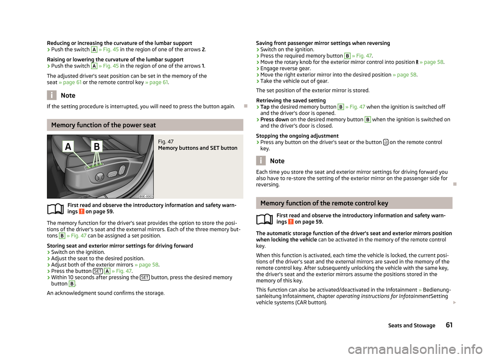
Fig. 47
Memory buttons and SET button
First read and observe the introductory information and safety warn-
ings on page 59.
The memory function for the driver's seat provides the option to store the posi- tions of the driver's seat and the external mirrors. Each of the three memory but-
tons
B
» Fig. 47 can be assigned a set position.
Storing seat and exterior mirror settings for driving forward
›
Switch on the ignition.
›
Adjust the seat to the desired position.
›
Adjust both of the exterior mirrors » page 58.
›
Press the button SET
A
» Fig. 47 .
›
Within 10 seconds after pressing the SET button, press the desired memory
button
B
.
An acknowledgment sound confirms the storage.
Saving front passenger mirror settings when reversing›Switch on the ignition.›
Press the required memory button
B
» Fig. 47 .
›
Move the rotary knob for the exterior mirror control into position » page 58 .
›
Engage reverse gear.
›
Move the right exterior mirror into the desired position » page 58.
›
Take the vehicle out of gear.
The set position of the exterior mirror is stored.
Retrieving the saved setting
›
Tap the desired memory button
B
» Fig. 47 when the ignition is switched off
and the driver's door is opened.
›
Press down on the desired memory button
B
when the ignition is switched on
and the driver's door is closed.
Stopping the ongoing adjustment
›
Press any button on the driver's seat or the button on the remote control
key.
Note
Each time you store the seat and exterior mirror settings for driving forward you
also have to re-store the setting of the exterior mirror on the passenger side for
reversing.
Memory function of the remote control key
First read and observe the introductory information and safety warn-ings
on page 59.
The automatic storage function of the driver's seat and exterior mirrors position
when locking the vehicle can be activated in the memory of the remote control
key.
When this function is activated, each time the vehicle is locked, the current posi-
tions of the driver's seat and the external mirrors are saved in the memory of the remote control key. After subsequently unlocking the vehicle with the same key,the driver's seat and the exterior mirrors assume the positions stored in the
memory of this key.
This function can also be activated/deactivated in the Infotainment » Bedienung-
sanleitung Infotainment, chapter operating instructions for Infotainment Setting
vehicle systems (CAR button).
61Seats and Stowage
Page 65 of 222
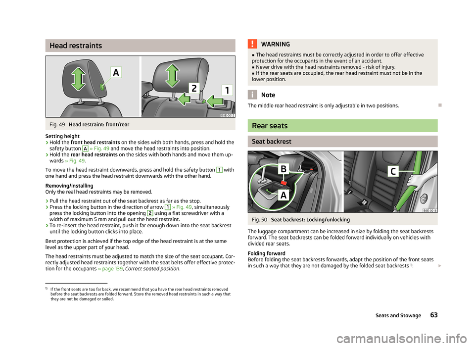
Head restraintsFig. 49
Head restraint: front/rear
Setting height
›
Hold the front head restraints on the sides with both hands, press and hold the
safety button
A
» Fig. 49 and move the head restraints into position.
›
Hold the rear head restraints on the sides with both hands and move them up-
wards » Fig. 49 .
To move the head restraint downwards, press and hold the safety button
1
with
one hand and press the head restraint downwards with the other hand.
Removing/installing
Only the real head restraints may be removed.
›
Pull the head restraint out of the seat backrest as far as the stop.
›
Press the locking button in the direction of arrow
1
» Fig. 49 , simultaneously
press the locking button into the opening
2
using a flat screwdriver with a
width of maximum 5 mm and pull out the head restraint.
›
To re-insert the head restraint, push it far enough down into the seat backrest
until the locking button clicks into place.
Best protection is achieved if the top edge of the head restraint is at the same
level as the upper part of your head.
The head restraints must be adjusted to match the size of the seat occupant. Cor-rectly adjusted head restraints together with the seat belts offer effective protec-
tion for the occupants » page 139, Correct seated position .
WARNING■
The head restraints must be correctly adjusted in order to offer effective
protection for the occupants in the event of an accident.■
Never drive with the head restraints removed - risk of injury.
■
If the rear seats are occupied, the rear head restraint must not be in the
lower position.
Note
The middle rear head restraint is only adjustable in two positions.
Rear seats
Seat backrest
Fig. 50
Seat backrest: Locking/unlocking
The luggage compartment can be increased in size by folding the seat backrests forward. The seat backrests can be folded forward individually on vehicles with
divided rear seats.
Folding forward
Before folding the seat backrests forwards, adapt the position of the front seats in such a way that they are not damaged by the folded seat backrests 1)
.
1)
If the front seats are too far back, we recommend that you have the rear head restraints removed
before the seat backrests are folded forward. Store the removed head restraints in such a way that
they are not be damaged or soiled.
63Seats and Stowage
Page 67 of 222
WARNING (Continued)■Please note that the handling properties of the vehicle may be affected
when transporting heavy objects as the centre of gravity can be displaced –
risk of accident! The speed and style of driving must be adjusted accordingly.■
If the items of luggage or objects are attached to the lashing eyes with un-
suitable or damaged lashing straps, injuries can occur in the event of braking manoeuvres or accidents. To prevent items of luggage from moving around,
always use suitable lashing straps which must be firmly attached to the lash-
ing eyes.
■
The items carried in the luggage compartment must be stored in such a way
that no objects are able to slip forward if any sudden driving or braking ma-
noeuvres are undertaken – risk of injury!
■
When transporting objects in the luggage compartment that has been en-
larged by folding the rear seats forward, ensure the safety of the passengers transported on the other rear seats » page 140, Correct seated position for
the occupants on the rear seats .
■
Do not drive with the luggage compartment lid fully opened or slightly ajar
otherwise exhaust gases may get into the interior of the vehicle – risk of poi-
soning!
■
Do not exceed the permissible axle loads and permissible gross weight of
the vehicle – risk of accident!
■
Do not transport people in the luggage compartment!
CAUTION
Make sure that transported objects with sharp edges do not damage the follow-
ing:■
heating elements in the rear window;
■
Elements of the aerial integrated in the rear window.
Note
Tyre pressure must be adjusted to the load » page 182
, Tyre life .
Boot light
First read and observe the introductory information and safety warn-
ings
on page 64.
The light switches on/off when the boot lid is opened or closed.
NoteIf the boot lid is open and the ignition switched off, the light will extinguish auto-
matically after around 10 minutes.
Fastening elements
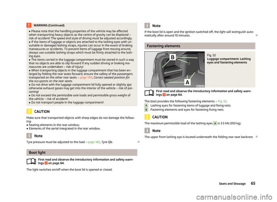
Fig. 52
Luggage compartment: Lashing
eyes and fastening elements
First read and observe the introductory information and safety warn- ings on page 64.
The boot provides the following fastening elements » Fig. 52.
Lashing eyes for fastening items of luggage and fixing nets.
Fastening elements and eyes for fastening fixing nets.
CAUTION
The maximum permissible load of the lashing eyes A is 3.5 kN (350 kg).
Note
The upper front lashing eye is located underneath the folding rear seat backrest.
AB65Seats and Stowage
Page 69 of 222
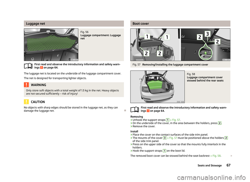
Luggage netFig. 56
Luggage compartment: Luggage
net
First read and observe the introductory information and safety warn-
ings on page 64.
The luggage net is located on the underside of the luggage compartment cover.
The net is designed for transporting lighter objects.
WARNINGOnly store soft objects with a total weight of 1.5 kg in the net. Heavy objects
are not secured sufficiently – risk of injury!
CAUTION
No objects with sharp edges should be stored in the luggage net, as they can
damage the luggage net.
Boot coverFig. 57
Removing/installing the luggage compartment cover
Fig. 58
Luggage compartment cover
stowed behind the rear seats
First read and observe the introductory information and safety warn-
ings on page 64.
Removing
›
Unhook the support straps
1
» Fig. 57 .
›
On the underside of the cover, in the area between the holders, press
2
.
›
Remove the cover.
Install
›
Place the cover on the contact surfaces of the side trim panel.
›
The mounts of the cover
3
» Fig. 57 must be positioned above the holders
2
of the side trim panel.
›
Press on the upper side of the cover so that the mounts fully interlock in the
holders.
›
Hook the support straps
1
on the boot lid.
The removed boot cover can be stowed behind the seat backrest » Fig. 58.
67Seats and Stowage
Page 71 of 222
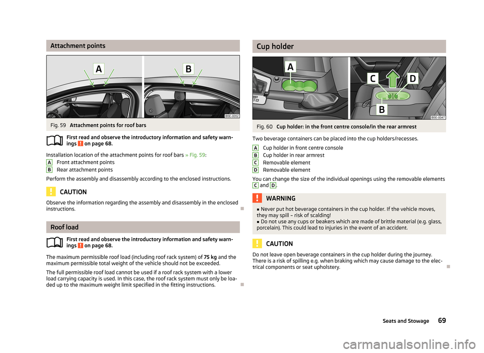
Attachment pointsFig. 59
Attachment points for roof bars
First read and observe the introductory information and safety warn- ings
on page 68.
Installation location of the attachment points for roof bars » Fig. 59:
Front attachment points
Rear attachment points
Perform the assembly and disassembly according to the enclosed instructions.
CAUTION
Observe the information regarding the assembly and disassembly in the enclosed
instructions.
Roof load
First read and observe the introductory information and safety warn-
ings
on page 68.
The maximum permissible roof load (including roof rack system) of 75 kg and the
maximum permissible total weight of the vehicle should not be exceeded.
The full permissible roof load cannot be used if a roof rack system with a lower
load carrying capacity is used. In this case, the roof rack system must only be loa-
ded up to the maximum weight limit specified in the fitting instructions.
ABCup holderFig. 60
Cup holder: in the front centre console/in the rear armrest
Two beverage containers can be placed into the cup holders/recesses. Cup holder in front centre console
Cup holder in rear armrest
Removable element
Removable element
You can change the size of the individual openings using the removable elements
C
and
D
.
WARNING■ Never put hot beverage containers in the cup holder. If the vehicle moves,
they may spill – risk of scalding!■
Do not use any cups or beakers which are made of brittle material (e.g. glass,
porcelain). This could lead to injuries in the event of an accident.
CAUTION
Do not leave open beverage containers in the cup holder during the journey.
There is a risk of spilling e.g. when braking which may cause damage to the elec-
trical components or seat upholstery.ABCD69Seats and Stowage
Page 72 of 222

AshtrayFig. 61
Centre console: Ashtray at the front/rear
Removing/inserting the front ash tray
›
Pull out the ashtray » Fig. 61 -
in the direction of the arrow.
Insertion takes place in the reverse order.
Removing/inserting the rear ashtray insert
›
Opening the stowage compartment » page 77.
›
Grasp the insert in the area marked with the arrows and remove it in the direc-
tion of the arrow
1
» Fig. 61 -
.
Insertion takes place in the reverse order.
WARNINGNever place flammable objects in the ashtray – risk of fire!
CAUTION
When removing do not hold the ashtray at the cover on the front– risk of break-
age.
Cigarette lighterFig. 62
Centre console: Cigarette lighter
Using the system
›
Press in the button of the cigarette lighter » Fig. 62.
›
Wait until the button pops forward.
›
Remove the cigarette lighter immediately and use.
›
Place the cigarette lighter back into the socket.
WARNING■
Take care when using the cigarette lighter! Improper usage can case burns.■The cigarette lighter also operates when the ignition is switched off or the
ignition key withdrawn. Therefore never leave children unattended in the ve-
hicle.
Note
Further information » page 165, Accessories, changes and replacement of parts .
70Using the system
Page 73 of 222
Sockets
12-Volt power socket
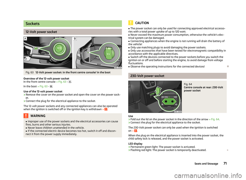
Fig. 63
12-Volt power socket: in the front centre console/ in the boot
Overview of the 12-volt power socket
In the front centre console » Fig. 63 -
.
In the boot » Fig. 63 -
.
Use of the 12-volt power socket
›
Remove the cover on the power socket and open the cover on the power sock-
et.
›
Connect the plug for the electrical appliance to the socket.
The 12-volt power sockets and any connected appliances can also be operated when the ignition is switched off or the ignition key is withdrawn »
.
WARNING■
Improper use of the power sockets and the electrical accessories can cause
fires, burns and other serious injuries.■
Never leave children unattended in the vehicle.
■
If the connected electric device becomes too hot, switch it off and discon-
nect it from the power supply immediately.
CAUTION■ The power socket can only be used for connecting approved electrical accesso-
ries with a total power uptake of up to 120 watt.■
Never exceed the maximum power consumption, otherwise the vehicle's elec-
trical system can be damaged.
■
Connecting appliances when the engine is not running will drain the battery of
the vehicle!
■
Only use matching plugs to avoid damaging the power sockets.
■
Only use accessories that have been tested for electromagnetic compatibility in
accordance with the applicable directives.
■
Switch off the devices connected to the power sockets before you switch the
ignition on or off and before starting the engine, to avoid damage from voltage
fluctuations.
■
Observe the operating instructions for the connected devices!
230-Volt power socket
Fig. 64
Centre console at rear: 230-Volt
power socket
Use
›
Fold out the lid on the power socket in the direction of the arrow » Fig. 64
.
›
Connect the plug for the electrical appliance to the socket.
The 230-Volt power socket can only be used when the ignition is switched on »
.
When the plug on the electrical appliance is inserted into the power socket, the
child safety lock is released, and the power socket is activated.
LED display › Permanent green light: The power socket is activated.
› Flashing red light: The power socket is temporarily deactivated.
71Seats and Stowage
Page 74 of 222
The power socket is deactivated automatically when the amperage is too high,
the temperature is too high or the battery charge state is too low.
When the reasons for the deactivation no longer apply, the power socket will be
re-activated automatically. Then re-activate connected devices which are switch- ed on »
.
WARNING■
The power socket can only be used for connecting approved electrical ac-
cessories with a two-pin 230V plug, with a total power uptake of up to
150 watt.■
The power sockets- and thus the connected electrical devices -only oper-
ates if the ignition is switched on!
■
Improper use can lead to serious injury or fire. Therefore never leave chil-
dren unattended in the vehicle - risk of injury!
■
Safely stow away all connected devices during the journey to prevent them
from being thrown around the interior in the event of a sudden braking ma- noeuvre or an accident - risk of death!
■
Do not pour liquids into the power socket - risk of death! If fluid does man-
age to get into the power socket, completely dry out the socket before reuse.
■
The connected appliances may behave differently to when connected to the
mains.
■
The connected devices may warm up during operation - risk of injury or fire!
■
The child lock on the 230 Volt power socket is unlocked when using ener-
gised adapters and extension cables - risk of injury!
■
Do no insert any conductive objects into the contacts of the power socket,
e.g knitting needs - risk of death!
CAUTION
■ Place the connector on the electrical device into the power socket as far as it
can go to create a connection between the contacts.■
If the connector of the electrical device is not inserted fully into the power sock-
et, the child safety lock might release, and the power socket be activated. The
electrical device is nevertheless not connected.
■
On vehicles with the START STOP system, when starting up the engine, the 230
Volt power socket is temporarily deactivated and the LED display flashes red. Af-
ter starting the engine, the power socket is re-activated automatically.
■
Do not connect any lamps with neon filaments to the 230 V power socket - risk
of damaging the lamp.
■ A larger current surge may arise in some power supplies (e.g. for notebooks)
when connecting them to a 230 V power socket- this will automatically deacti-
vate the power socket. In this case, disconnect the power supply from the con-
sumer and connect the power supply to the power socket first, followed by the
consumer.■
Observe the operating instructions for the connected devices!
Storage compartments
Overview
The vehicle has the following storage compartments:
Storage compartment on the front passenger side» page 73Storage compartment on the driver's side» page 73Holder for reflex vest» page 74Stowage compartment in front centre console» page 74Multimedia holder» page 74Map pockets in the front seats» page 75Glasses storage box» page 75Storage compartments in the doors» page 75Stowage compartment below front passenger seat» page 76Front armrest with storage compartment» page 76Stowage compartment in rear centre console» page 77Seat backrest with through-loading channel» page 77Removable through-loading bag» page 77Storage compartment in the boot» page 78Storage box underneath the luggage compartment cov-
er» page 79 72Using the system