display SKODA OCTAVIA 2013 3.G / (5E) Owner's Guide
[x] Cancel search | Manufacturer: SKODA, Model Year: 2013, Model line: OCTAVIA, Model: SKODA OCTAVIA 2013 3.G / (5E)Pages: 287, PDF Size: 18.55 MB
Page 44 of 287
WARNING■Make sure that the door has closed correctly as it can open suddenly while
driving – risk of death!■
Only open and close the door when there is no one in the opening/closing
range – risk of injury!
■
An opened door can close automatically if there is a strong wind or the vehi-
cle is on an incline – risk of injury!
KESSY
Introduction
This chapter contains information on the following subjects:
Information message
41
Parking vehicle
41
The KESSY system (Keyless Entry Start Exit System) enables unlocking and lock-
ing of the vehicle without actively using the remote control key.
Information message
First read and observe the introductory information given on page 41.
Key in the vehicle
The protection against inadvertently locking the key in the vehicle unlocks the vehicle automatically if the following conditions are met.
The vehicle, including the boot lit, has been locked.The key with which the vehicle has been locked remains in the vehicle in the
zone
D
» Fig. 14 on page 38.
The turn signal lights flash four times as confirmation that the vehicle has been
unlocked again.
The following message is shown in the information cluster display. Key in vehicle.
KEY IN VEHICLE
Additionally, on vehicles which are fitted with the anti-theft alarm system, an au-
dible signal sounds.
The system has not found a key
If the system has not found a key in the vehicle, the following message appears in the display of the instrument cluster.
Key not found.
Key not detected. Owner's manual!
NO KEY
This can occur if the key is outside the vehicle, the battery in the key is dis-
charged, the key is defective or the electromagnetic field is strongly disturbed.
Fault in KESSY system
If there is a fault in the KESSY system, the following message will appear in the display of the instrument cluster.
Keyless access system faulty.
KEYLESS ACCESS SYSTEM FAULTY
Low voltage of the key battery
If the voltage of the battery in the remote control key is too low, the following message appears in the display of the instrument cluster.
Change the key battery!
KEY BATTERY PLEASE CHANGE
Change the key battery » page 247!
Parking vehicle
First read and observe the introductory information given on page 41.
If the vehicle is not unlocked within 60 or 90 hours, the sensors in the handle of
the driver or front passenger's door are deactivated automatically » Fig. 14 on
page 38.
Activation after 60 hours
›
Unlock the driver's door using the sensor
2
» Fig. 14 on page 38.
›
Press the handle of the boot lid.
›
Unlock the vehicle using the symbol button
on the remote control key.
›
Unlocking the driver's door in an emergency » page 248.
41Unlocking and opening
Page 61 of 287
The mode is active at speeds of 15 – 70 km/h and if the rear fog light is switchedon for a period of time longer than 10 seconds. The mode is deactivated when the
rear fig light is switched off for longer than 5 seconds.
Dynamic cornering lights
The cone of light in front of the vehicle is adjusted to the steering angle so that the road in the curve is illuminated. This function is active at speeds greater than
10 km.h and in all AFS modes.
Tourist light (Travel mode)
This mode makes it possible to drive in countries with opposing traffic system (driving on the left/right) without dazzling the oncoming vehicles.
When the “tourist light” mode is active, the above-mentioned modes and the side
swivel of the headlights is deactivated.
The "Tourist light" mode can be configured in the Infotainment » Operating in-
structions for Infotainment , chapter Vehicle settings (CAR button) .WARNINGIf the AFS system is defective, the headlights are automatically lowered to the
emergency position, which prevents a possible dazzling of oncoming traffic. This reduces the cone of light in front of the vehicle. Drive carefully and visit a
specialist garage as soon as possible.
Note
If the Eco driving mode is selected, the AFS system is deactivated » page 161.
Headlight assist
Fig. 31
Operating lever: Headlight assist
First read and observe the introductory information and safety warn-
ings on page 54.
The Headlight assist switches the headlights on/off automatically depending on
the environmental conditions.
The headlight is regulated based on data gathered by the camera attached be-
tween the windscreen and interior mirror.
The function of high beam assist can be activated or deactivated in the Infotain-ment » Operating instructions for Infotainment , chapter Vehicle settings (CAR
button) .
The headlight can switch off automatically at speeds above 60 km/h. The head-
light switches off automatically when the speed falls below 30 km/h.
When the assistant automatically switches on the main beam, warning light
is
lit in the instrument cluster.
Activating
›
Turn the light switch to the
» Fig. 30 on page 57 position.
›
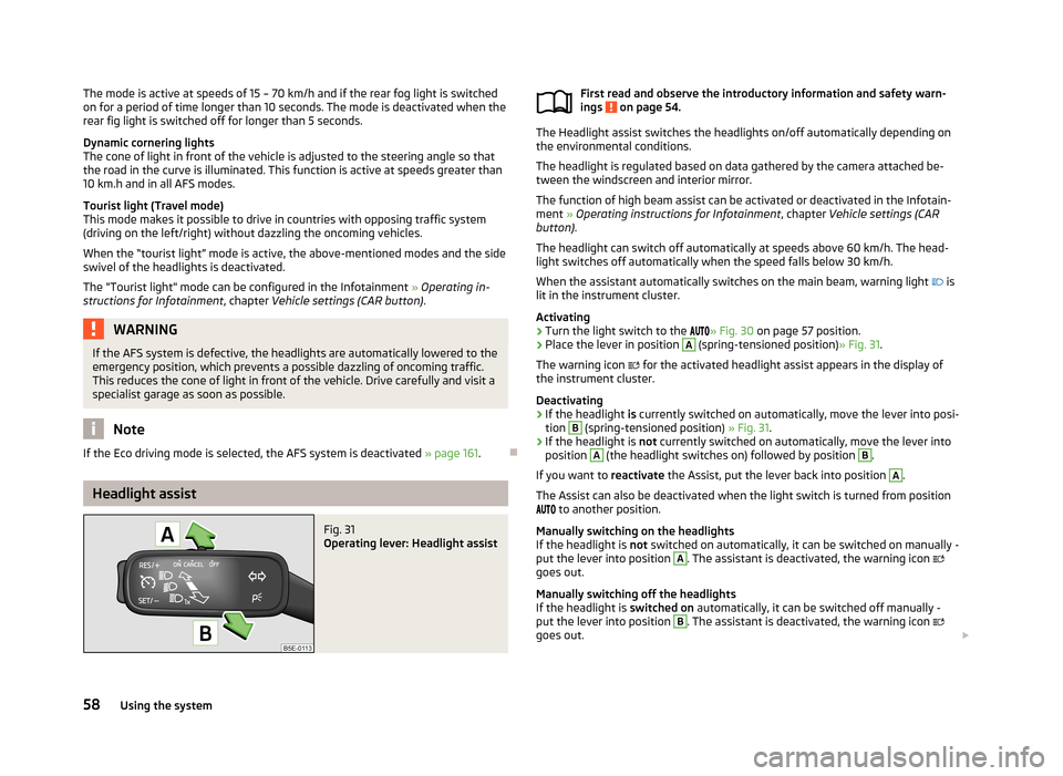
Place the lever in position
A
(spring-tensioned position) » Fig. 31.
The warning icon
for the activated headlight assist appears in the display of
the instrument cluster.
Deactivating
›
If the headlight is currently switched on automatically, move the lever into posi-
tion
B
(spring-tensioned position) » Fig. 31.
›
If the headlight is not currently switched on automatically, move the lever into
position
A
(the headlight switches on) followed by position
B
.
If you want to reactivate the Assist, put the lever back into position
A
.
The Assist can also be deactivated when the light switch is turned from position
to another position.
Manually switching on the headlights
If the headlight is not switched on automatically, it can be switched on manually -
put the lever into position
A
. The assistant is deactivated, the warning icon
goes out.
Manually switching off the headlights
If the headlight is switched on automatically, it can be switched off manually -
put the lever into position
B
. The assistant is deactivated, the warning icon
goes out.
58Using the system
Page 62 of 287
Information message
The messages and information are indicated in the instrument cluster display. Fault: Light Assist
LIGHT ASSIST FAULT
Seek help from a specialist garage. Light Assist: clean the windscreen!
WINDSCREEN PLEASE CLEAN
Check for any obstacles on the windscreen in the viewing area of the camera.WARNINGHeadlight assist only functions as a support and does not relieve the driver of
his responsibility to check the headlights and light beam and, if necessary, to
switch on the lights depending on the light conditions. Manual operation may be required in the following situations.■
Poor visibility conditions, e.g. fog, heavy rain, thick snowfall.
■
The oncoming traffic is partially blocked on roads or motorways.
■
Passing poorly lit road users, e.g. cyclists.
■
Driving around “sharp” curves.
■
Driving on sharp slopes up/large inclines.
■
Driving through poorly-lit locations.
■
Driving over highly reflective surfaces.
■
The windscreen around the camera is dirty, iced up, misted up, or covered by
stickers.
■
Near the camera lens there is a light source, such as the screen of an exter-
nal navigation system.
CAUTION
Do not attach any stickers or similar objects to the windscreen to avoid impairing
the functions of the Assist system.Fog lightsFig. 32
Light switch
First read and observe the introductory information and safety warn-
ings on page 54.
Switching on/off
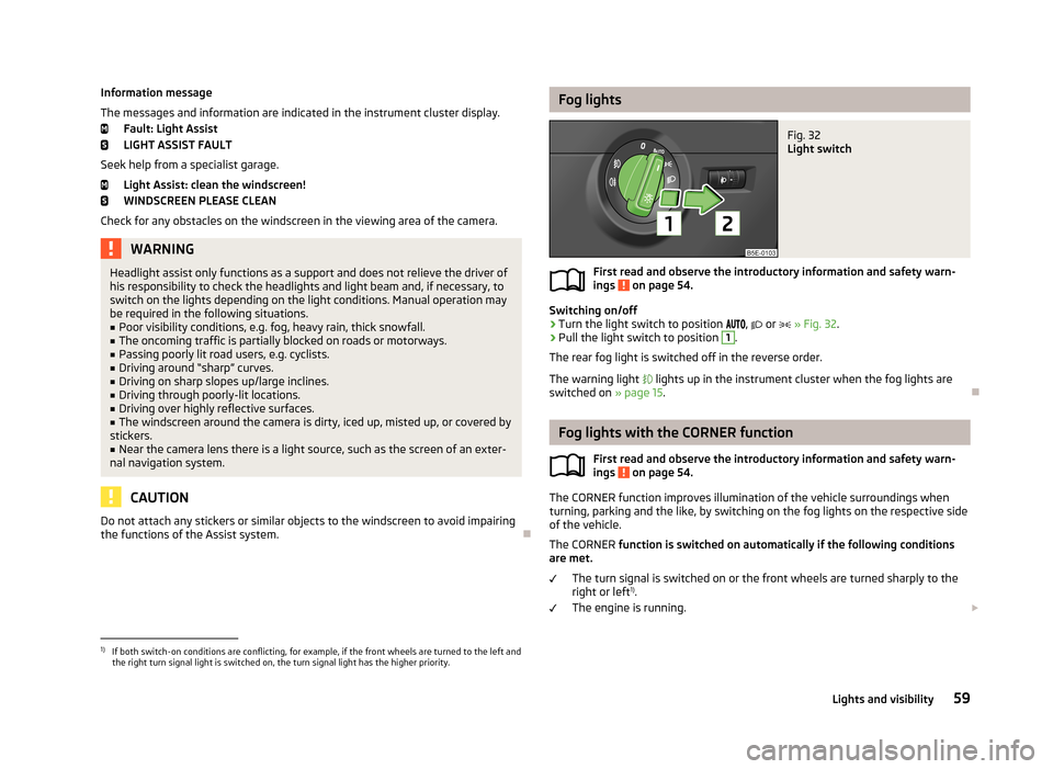
›
Turn the light switch to position
,
or
» Fig. 32 .
›
Pull the light switch to position
1
.
The rear fog light is switched off in the reverse order.
The warning light
lights up in the instrument cluster when the fog lights are
switched on » page 15.
Fog lights with the CORNER function
First read and observe the introductory information and safety warn-ings
on page 54.
The CORNER function improves illumination of the vehicle surroundings when
turning, parking and the like, by switching on the fog lights on the respective side
of the vehicle.
The CORNER function is switched on automatically if the following conditions
are met.
The turn signal is switched on or the front wheels are turned sharply to the
right or left 1)
.
The engine is running.
1)
If both switch-on conditions are conflicting, for example, if the front wheels are turned to the left and
the right turn signal light is switched on, the turn signal light has the higher priority.
59Lights and visibility
Page 71 of 287
Rear mirror
Introduction
This chapter contains information on the following subjects:
Interior mirror
69
Exterior mirrors
69WARNING■ Make sure that the mirror is not covered by ice, snow, mist or other objects.■Convex (curved outward) or aspheric exterior mirrors increase the field of vi-
sion. They do, however, make objects appear smaller in the mirror. These mir-
rors are therefore only of limited use for estimating distances to the following
vehicles.■
Whenever possible use the interior mirror for estimating the distances to
the following vehicles.
■
The illuminated display of an external navigation unit can lead to operation-
al faults to the automatic dimming interior mirror – risk of accident.
WARNINGAutomatic dimming mirrors contain an electrolytic fluid which may leak should
the mirror glass break.■
The leaking electrolytic fluid can irritate the skin, eyes and breath apparatus.
Immediately seek out fresh air and leave the vehicle. If this is not possible,
open all windows and doors.
■
If you swallow electrolytic fluid, seek medical assistance immediately.
■
If your eyes or skin come into contact with the electrolytic fluid, immediately
wash the affected area for a few minutes long with a lot of water. Then con-
sult a doctor immediately.
CAUTION
Never mechanically fold in or fold back the exterior mirrors with the fold-in func-
tion by hand as this will damage the electric drive.Note■
Automatic mirror dimming operates only properly if the sun screen for the rear
window in the housing on the boot cover is not in use or the light striking the in- terior rear-view mirror is not affected by other objects.■
If the automatic interior mirror dimming is switched off, the exterior mirror dim-
ming is also switched off.
■
The mirror heater only operates when the engine is running and up to an out-
side temperature of +35 ℃.
■
Do not touch the surface of the exterior mirrors if the exterior mirror heater is
switched on.
■
If the electrical exterior mirror setting fails at any time, the mirrors can be adjus-
ted by hand by pressing on the edge of the mirror surface.
■
Contact a specialist garage if there is a fault with the power setting function for
the exterior mirrors.
68Using the system
Page 92 of 287
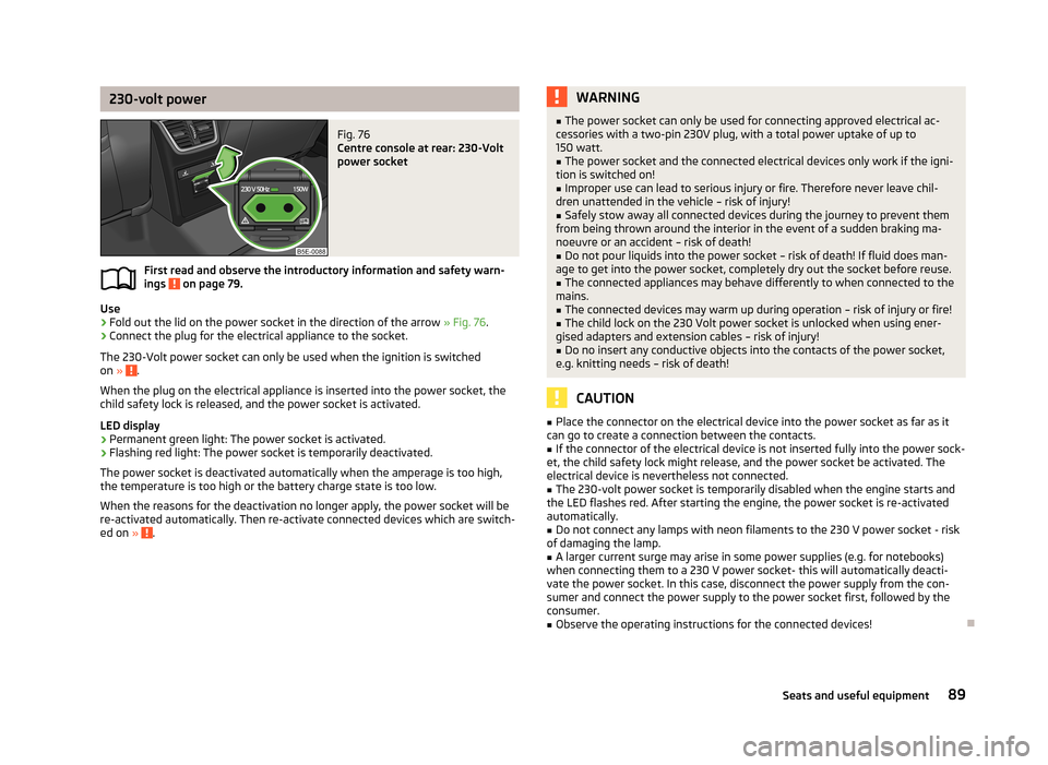
230-volt powerFig. 76
Centre console at rear: 230-Volt
power socket
First read and observe the introductory information and safety warn-
ings on page 79.
Use
›
Fold out the lid on the power socket in the direction of the arrow » Fig. 76.
›
Connect the plug for the electrical appliance to the socket.
The 230-Volt power socket can only be used when the ignition is switched on »
.
When the plug on the electrical appliance is inserted into the power socket, the
child safety lock is released, and the power socket is activated.
LED display › Permanent green light: The power socket is activated.
› Flashing red light: The power socket is temporarily deactivated.
The power socket is deactivated automatically when the amperage is too high, the temperature is too high or the battery charge state is too low.
When the reasons for the deactivation no longer apply, the power socket will be
re-activated automatically. Then re-activate connected devices which are switch-
ed on »
.
WARNING■
The power socket can only be used for connecting approved electrical ac-
cessories with a two-pin 230V plug, with a total power uptake of up to 150 watt.■
The power socket and the connected electrical devices only work if the igni-
tion is switched on!
■
Improper use can lead to serious injury or fire. Therefore never leave chil-
dren unattended in the vehicle – risk of injury!
■
Safely stow away all connected devices during the journey to prevent them
from being thrown around the interior in the event of a sudden braking ma- noeuvre or an accident – risk of death!
■
Do not pour liquids into the power socket – risk of death! If fluid does man-
age to get into the power socket, completely dry out the socket before reuse.
■
The connected appliances may behave differently to when connected to the
mains.
■
The connected devices may warm up during operation – risk of injury or fire!
■
The child lock on the 230 Volt power socket is unlocked when using ener-
gised adapters and extension cables – risk of injury!
■
Do no insert any conductive objects into the contacts of the power socket,
e.g. knitting needs – risk of death!
CAUTION
■ Place the connector on the electrical device into the power socket as far as it
can go to create a connection between the contacts.■
If the connector of the electrical device is not inserted fully into the power sock-
et, the child safety lock might release, and the power socket be activated. The
electrical device is nevertheless not connected.
■
The 230-volt power socket is temporarily disabled when the engine starts and
the LED flashes red. After starting the engine, the power socket is re-activated
automatically.
■
Do not connect any lamps with neon filaments to the 230 V power socket - risk
of damaging the lamp.
■
A larger current surge may arise in some power supplies (e.g. for notebooks)
when connecting them to a 230 V power socket- this will automatically deacti-
vate the power socket. In this case, disconnect the power supply from the con-
sumer and connect the power supply to the power socket first, followed by the
consumer.
■
Observe the operating instructions for the connected devices!
89Seats and useful equipment
Page 115 of 287
WARNINGNever leave recirculated air mode switched on over a longer period of time, as
“stale air” can cause driver and passenger fatigue, reduce attention levels and
also cause the windows to mist up. The risk of having an accident increases.
Switch off recirculated air mode as soon as the windows start to mist up.
Climatronic (automatic air conditioning system)
Introduction
This chapter contains information on the following subjects:
Control elements
112
Automatic mode
113
Switching the cooling system on/off
113
Setting temperature
113
Automatic recirculation mode
114
Controlling blower
114
Defrosting windscreen
115
The Climatronic in automatic mode ensures the best-possible setting of the tem-
perature of the outflowing air, the blower stage and air distribution.
The system also takes sunlight into account, which eliminates the need to alterthe settings manually.
The cooling system only operates if the following conditions are met. The cooling system is switched on » page 112, Control elements .
The engine is running.
The outside temperature above approx. +2 °C.
The cooling system is switched off at a high coolant temperature in order to pro-
vide cooling at a high load of the engine.
Note
We recommend that you have Climatronic cleaned by a specialist garage once ev-
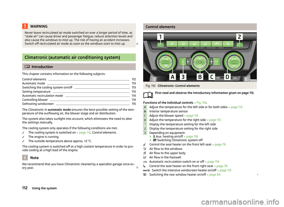
ery year.Control elementsFig. 110
Climatronic: Control elements
First read and observe the introductory information given on page 112.
Functions of the individual controls » Fig. 110 .
Adjust the temperature for the left side or for both sides » page 113
Interior temperature sensor
Adjust the blower speed » page 114
Adjust the temperature for the right side » page 113
Display the temperature setting for the left side
Display the temperature setting for the right side
Depending on equipment:
›
Aux. heating on/off » page 116
›
Switching Climatronic system off
Control the seat heater on the front left seat » page 76
Air flow to the windows
Air flow to the upper body
Air flow in the footwell
Automatic recirculation switch on or off » page 114
Control the seat heater on the front right seat » page 76
Switch the intensive windscreen heater on/off » page 115
Switching the rear window heater on/off » page 64
ABCD123112Using the system
Page 116 of 287
Switching the windscreen heater on/off » page 64
Climatronic set in the Infotainment » Operating instructions for Infotain-
ment
Switch the temperature setting in Dual mode on/off » page 113
Switching automatic mode on » page 113
Switching the cooling system on/off » page 113
Note
Do not stick anything onto or cover the interior temperature sensor 11 » Fig. 110
as this could impair the functioning of the Climatronic.
Automatic mode
First read and observe the introductory information given on page 112.
Automatic mode works in three modes - moderate, medium, and intensive.Setting the individual operating modes » Operating instructions for Infotainment ,
chapter Vehicle settings .
Climatronic is set to the medium setting at the factory.
Recommended setting for all periods of the year
›
Set the desired temperature, we recommend 22 °C.
›
Press the button
» Fig. 110 on page 112.
›
Set the air outlet vents 3 and 4 » Fig. 106 on page 107 so that the air flow is
directed slightly upwards.
After the automatic mode is switched on, Climatronic works in the last selected
mode.
The currently selected mode is displayed in the Infotainment display. Automatic mode can be switched off by pressing one of the buttons for the air
distribution or by increasing/decreasing the blower speed.
Switching the cooling system on/off
First read and observe the introductory information given on page 112.
›
Press the symbol button
.
The warning light in the button lights up.›
Press the symbol button
again.
The warning light in the button goes out.
After the cooling system is switched off, only the ventilation function remains ac-
tive whereby the minimum temperature that can be reached is the outside tem-
perature.
Setting temperature
First read and observe the introductory information given on page 112.
The interior temperature for the left and right side can be set separately or to-
gether.
For both sides
›
Turn the control dial
A
» Fig. 110 on page 112 to the left or right to increase or
decrease the temperature.
The warning light in the symbol button
does not light up.
For the right side
›
Turn the control dial
D
» Fig. 110 on page 112 to the left or right to increase or
decrease the temperature.
The warning light in the symbol button
lights up.
If the warning light in the symbol button
is lit, the temperature for both sides
cannot be set with the control dial
A
. This function can be resumed by pressing
the symbol button
. The warning light in the button goes out.
The interior temperature can be set between +16 ℃ and +29 ℃. The interior tem-
perature is regulated automatically within this range.
If a temperature lower than +16 ℃ is selected, a blue symbol lights up on the cor-
responding control dial.
If a temperature higher than +29 ℃ is selected, a red symbol lights up on the cor-
responding control dial.
At both end positions, Climatronic runs at maximum cooling/heating output and
the temperature is automatically not regulated.
113Heating and air-conditioning
Page 117 of 287
CAUTIONLengthy and uneven distribution of the air flow out of the vents (especially
around the feet) and large differences in temperature, for example, when getting
out of the vehicle, can cause susceptible individuals to catch a cold.
Automatic recirculation mode
First read and observe the introductory information given on page 112.
Recirculated air mode prevents polluted air outside the vehicle from getting into
the vehicle, for example when driving through a tunnel or when standing in a
traffic jam.
If a considerable increase in concentration of pollutants is recognised by the air
quality sensor, recirculated air mode will temporarily be switched off.
If the concentration of pollutants decreases to the normal level, the air distribu-
tion control is automatically switched off so that fresh air can be guided into the
vehicle interior.
In recirculated air mode air is sucked out of the interior of the vehicle and then
fed back into the interior. When the automatic air distribution control is switched on, an air quality sensor measures the concentration of pollutants in the drawn in
air.
If the air quality sensor does not switch on automatic recirculated air mode when
there is an unpleasant smell, you can switch in on manually.
Switching on/off
›
Press the symbol button
.
The warning light below the button lights up.
›
Press the symbol button
again; the warning light below the button goes out;
if necessary, press the symbol button
again.
Switching on and off is also possible in the Infotainment » Operating instructions
for Infotainment , chapter Vehicle settings .
WARNINGNever leave recirculated air mode switched on over a longer period of time, as
“stale air” can cause driver and passenger fatigue, reduce attention levels and
also cause the windows to mist up. The risk of having an accident increases.
Switch off recirculated air mode as soon as the windows start to mist up.
Note
■ If the windscreen mists up, press the symbol button . Press the symbol
button when the windscreen is demisted.■
The automatic air distribution control operates only if the outside temperature
is higher than approx. 2 °C.
Controlling blower
First read and observe the introductory information given on page 112.
The blower stage can be manually adapted to suit your particular needs.
›
Turn the control dial
C
» Fig. 110 on page 112 to the left or right to increase or
decrease the temperature.
If the blower speed is reduced to a minimum, Climatronic is switched off.
The set blower speed is displayed in the control dial
C
when the respective num-
ber of warning lights illuminate.
WARNING■ “Stale air” may result in fatigue in the driver and occupants, reduce attention
levels and also cause the windows to mist up. The risk of having an accident
increases.■
Do not switch off the Climatronic system for longer than necessary.
■
Switch on the Climatronic system as soon as the windows mist up.
114Using the system
Page 118 of 287
Defrosting windscreenFirst read and observe the introductory information given on page 112.
Switching on/off
›
Press the symbol button » Fig. 110 on page 112.
›
Press the symbol button again or press the symbol button .
More air flows out of the air outlet vents 1 » Fig. 106 on page 107. The tempera-
ture control is controlled automatically.
Auxiliary heating (auxiliary heating and ventilation)
Introduction
This chapter contains information on the following subjects:
Switching on/off
116
Radio remote control
116
Conditions for the functioning of auxiliary heating (Aux. heating and ventilation),
hereinafter referred to only as auxiliary heating (Aux. heating).
The charge state of the vehicle battery is sufficient.
The fuel supply is adequate (the warning icon
is not lit in the display of the
instrument cluster).
Auxiliary ventilation
The auxiliary ventilation enables fresh air to flow into the vehicle interior by
switching off the engine, whereby the interior temperature is effectively de-
creased (e.g. with the vehicle parked in the sun).
Auxiliary heating (parking heating)
The auxiliary heating (parking heating) can be used when stationary, when the engine is switched off to preheat the vehicle and while driving (e.g. during the
heating phase of the engine).
The auxiliary heater (parking heater) functions in connection with the air-condi-
tioning system or Climatronic.
The auxiliary heating (parking heating) also warms up the engine.
The auxiliary heating (parking heating) warms up the coolant by combusting fuel
from the vehicle tank. The coolant heats air flowing into the passenger compart- ment (as long as the blower fan speed B
» Fig. 108 on page 108 or
C
» Fig. 110
on page 112 is not set to zero).
WARNING■ The auxiliary heater (independent vehicle heater) must never be operated in
closed rooms (e.g. garages) – risk of poisoning!■
The auxiliary heating (parking heating) must not be running during refuelling
– risk of fire.
■
The exhaust pipe of the auxiliary heating is located underneath the vehicle.
Therefore, if you wish to operate the auxiliary heating (parking heating), do
not park the vehicle in such a way that the exhaust gases can come into con-
tact with highly flammable materials (e.g. dry grass) or easily inflammable sub-
stances (e.g. spilt fuel) – risk of fire.
CAUTION
■ The running auxiliary heating (parking heating) consumes fuel from the vehicle
tank and automatically controls the filling level. If only a low quantity of fuel is
present in the fuel tank, the auxiliary heater switches itself off.■
The exhaust pipe of the auxiliary heating, which is located underneath the vehi-
cle, must not be clogged up and the exhaust flow must not be blocked.
■
If the auxiliary heating is running, the vehicle battery discharges. If the auxiliary
heating and ventilation has been operated several times over a longer period, the
vehicle must be driven a few kilometres in order to recharge the vehicle battery.
Note
■ The auxiliary heating (aux. heating) switches on the blower B » Fig. 108 on
page 108 or C » Fig. 110 on page 112 only if it has achieved a coolant temperature
of approx. 50 °C.■
At low outside temperatures, this can result in a formation of water vapour in
the area of the engine compartment. This is quite normal and is not an operating problem.
■
The air inlet in front of the windscreen must be free of e.g. ice, snow or leaves
to ensure that the auxiliary heating and cooling system operates properly.
■
So that warm air can flow into the vehicle interior after switching on the auxili-
ary heating, you must maintain the comfort temperature normally selected by
you, leave the fan switched on and leave the air outlet vents in an open position.
It is recommended to put the air flow in the position or .
115Heating and air-conditioning
Page 120 of 287
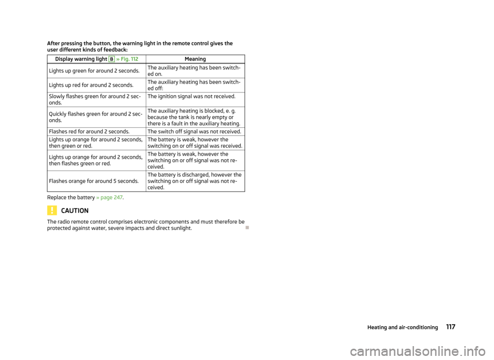
After pressing the button, the warning light in the remote control gives the
user different kinds of feedback:Display warning light B » Fig. 112MeaningLights up green for around 2 seconds.The auxiliary heating has been switch-
ed on.Lights up red for around 2 seconds.The auxiliary heating has been switch-
ed off:Slowly flashes green for around 2 sec- onds.The ignition signal was not received.Quickly flashes green for around 2 sec-
onds.The auxiliary heating is blocked, e. g.
because the tank is nearly empty or
there is a fault in the auxiliary heating.Flashes red for around 2 seconds.The switch off signal was not received.Lights up orange for around 2 seconds,
then green or red.The battery is weak, however the
switching on or off signal was received.Lights up orange for around 2 seconds,
then flashes green or red.The battery is weak, however the
switching on or off signal was not re-
ceived.Flashes orange for around 5 seconds.The battery is discharged, however the
switching on or off signal was not re-
ceived.
Replace the battery » page 247.
CAUTION
The radio remote control comprises electronic components and must therefore be
protected against water, severe impacts and direct sunlight.
117Heating and air-conditioning