coolant level SKODA OCTAVIA 2013 3.G / (5E) Owner's Manual
[x] Cancel search | Manufacturer: SKODA, Model Year: 2013, Model line: OCTAVIA, Model: SKODA OCTAVIA 2013 3.G / (5E)Pages: 287, PDF Size: 18.55 MB
Page 14 of 287

Instruments and warning lights
Instrument cluster
Introduction
This chapter contains information on the following subjects:
Overview
11
Revolutions counter
12
Display
12
Speedometer
12
Coolant temperature gauge
13
Fuel gauge
13
Counter for distance driven
14
14
Viewing the charge level vehicle battery
14
Auto-check control
14
Component protection
If the message SAFE CP appears in the instrument cluster display, the component
protection for the instrument cluster is active. Further information » page 202,
Component protection .
Fault display
If there is a fault in the instrument cluster, the following message will appear in
the display.
Error: instrument cluster. Workshop!COMBIINSTRUM_ WORKSHOP
Seek help from a specialist garage.
WARNING■ Concentrate fully at all times on your driving! As the driver you are fully re-
sponsible for road safety.■
Never operate the button
6
in the instrument cluster » Fig. 2 on page 11
while driving, only when the vehicle is stationary!
Overview
Fig. 2
Instrument cluster
First read and observe the introductory information and safety warn-
ings
on page 11.
Revolutions counter with warning lights » page 12
Display » page 12
› With counter for distance driven
» page 14
› With service interval display
» page 33
› With digital clock
» page 14
› With information system
» page 26
› With control symbols
» page 21
Speedometer 1)
with warning lights » page 12
Coolant temperature gauge » page 13
12341)
During the journey, the speed can be displayed in a different unit (mph or km/h) in addition to the
tachometer display.
11Instruments and warning lights
Page 16 of 287

Coolant temperature gaugeFig. 4
Coolant temperature gauge
First read and observe the introductory information and safety warn-
ings on page 11.
The coolant temperature gauge » Fig. 4 only operates when the ignition is
switched on.
Cold range
If the pointer is still in the left area of the scale, this indicates that the engine has
not yet reached its operating temperature. Avoid high speeds, full throttle and
high engine loads. This prevents possible damage to the engine.
The operating range
The engine has reached its operating temperature as soon as the pointer moves into the mid-range of the scale. At very high ambient temperatures or heavy en-
gine loads, the pointer may move even further to the right.
High temperature range
If the pointer reaches the red area of the scale, the coolant temperature is too high. Further information » page 22.
CAUTION
Additional headlights and other attached components in front of the air inlet im-
pair the cooling efficiency of the coolant.
Fuel gaugeFig. 5
Fuel gauge
First read and observe the introductory information and safety warn-
ings on page 11.
The fuel gauge » Fig. 5 only operates if the ignition is switched on.
The fuel tank has a capacity of about 50 litres. If the amount of fuel reaches the reserve area (the pointer reaches the red scale range), the indicator symbol illumi-
nates
to » page 25 .
CAUTION
Never drive until the fuel tank is completely empty! The irregular supply of fuel
can cause misfiring. This can result in considerable damage to parts of the engine
and the exhaust system.
Note
■ After filling up, it can occur that during dynamic driving (e.g. numerous curves,
braking, driving downhill and climbing a steep hill) the fuel gauge indicates ap-
prox. a fraction less. When stopping or during less dynamic driving, the fuel gauge displays the correct fuel level again. This is not a fault.■
The arrow next to the icon within the fuel gauge displays the installation
location of the fuel filler on the right side of the vehicle.
13Instruments and warning lights
Page 24 of 287
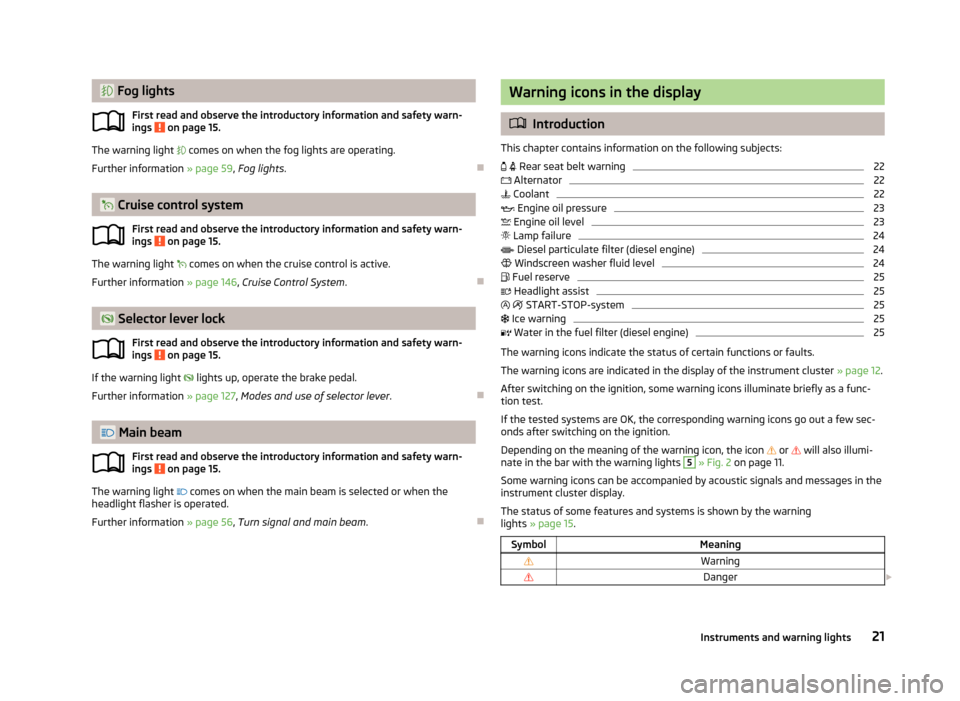
Fog lightsFirst read and observe the introductory information and safety warn-
ings
on page 15.
The warning light comes on when the fog lights are operating.
Further information » page 59, Fog lights .
Cruise control system
First read and observe the introductory information and safety warn-
ings
on page 15.
The warning light
comes on when the cruise control is active.
Further information » page 146, Cruise Control System .
Selector lever lock
First read and observe the introductory information and safety warn-
ings
on page 15.
If the warning light
lights up, operate the brake pedal.
Further information » page 127, Modes and use of selector lever .
Main beam
First read and observe the introductory information and safety warn-ings
on page 15.
The warning light
comes on when the main beam is selected or when the
headlight flasher is operated.
Further information » page 56, Turn signal and main beam .
Warning icons in the display
Introduction
This chapter contains information on the following subjects:
Rear seat belt warning
22
Alternator
22
Coolant
22
Engine oil pressure
23
Engine oil level
23
Lamp failure
24
Diesel particulate filter (diesel engine)
24
Windscreen washer fluid level
24
Fuel reserve
25
Headlight assist
25
START-STOP-system
25
Ice warning
25
Water in the fuel filter (diesel engine)
25
The warning icons indicate the status of certain functions or faults.
The warning icons are indicated in the display of the instrument cluster » page 12.
After switching on the ignition, some warning icons illuminate briefly as a func- tion test.
If the tested systems are OK, the corresponding warning icons go out a few sec-
onds after switching on the ignition.
Depending on the meaning of the warning icon, the icon
or
will also illumi-
nate in the bar with the warning lights
5
» Fig. 2 on page 11.
Some warning icons can be accompanied by acoustic signals and messages in the
instrument cluster display.
The status of some features and systems is shown by the warning
lights » page 15 .
SymbolMeaningWarningDanger 21Instruments and warning lights
Page 25 of 287
While the operational faults remain unrectified, the messages are always indica-
ted again. After they are displayed for the first time, the symbols or continue
to be indicated without any extra messages for the driver.
On vehicles with a colour MAXI DOT display some warning icons in the display are
in colour.WARNING■ Ignoring illuminated warning icons and related messages or instructions in
the display of the instrument cluster may lead to serious personal injury or
damage to the vehicle.■
If you have to stop for technical reasons, then park the vehicle at a safe dis-
tance from the traffic, switch off the engine and activate the hazard warning
light system » page 61. The warning triangle must be set up at the prescri-
bed distance - observe the national legal provisions when doing so.
■
The engine compartment of your car is a hazardous area. While working in
the engine compartment, be sure to observe the following warn-
ings » page 215 , Engine compartment .
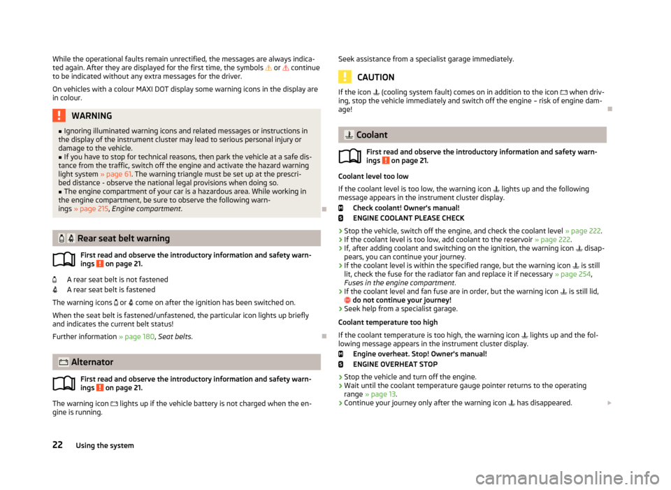
Rear seat belt warning
First read and observe the introductory information and safety warn-
ings
on page 21.
A rear seat belt is not fastened
A rear seat belt is fastened
The warning icons
or
come on after the ignition has been switched on.
When the seat belt is fastened/unfastened, the particular icon lights up briefly and indicates the current belt status!
Further information » page 180, Seat belts .
Alternator
First read and observe the introductory information and safety warn-
ings
on page 21.
The warning icon
lights up if the vehicle battery is not charged when the en-
gine is running.
Seek assistance from a specialist garage immediately.
CAUTION
If the icon (cooling system fault) comes on in addition to the icon when driv-
ing, stop the vehicle immediately and switch off the engine – risk of engine dam- age!
Coolant
First read and observe the introductory information and safety warn-ings
on page 21.
Coolant level too low
If the coolant level is too low, the warning icon
lights up and the following
message appears in the instrument cluster display.
Check coolant! Owner's manual!
ENGINE COOLANT PLEASE CHECK
› Stop the vehicle, switch off the engine, and check the coolant level
» page 222.
› If the coolant level is too low, add coolant to the reservoir
» page 222.
› If, after adding coolant and switching on the ignition, the warning icon
disap-
pears, you can continue your journey.
› If the coolant level is within the specified range, but the warning icon
is still
lit, check the fuse for the radiator fan and replace it if necessary » page 254,
Fuses in the engine compartment .
› If the coolant level and fan fuse are in order, but the warning icon
is still lid,
do not continue your journey!
› Seek help from a specialist garage.
Coolant temperature too high
If the coolant temperature is too high, the warning icon
lights up and the fol-
lowing message appears in the instrument cluster display.
Engine overheat. Stop! Owner's manual!
ENGINE OVERHEAT STOP
› Stop the vehicle and turn off the engine.
› Wait until the coolant temperature gauge pointer returns to the operating
range » page 13 .
› Continue your journey only after the warning icon
has disappeared.
22Using the system
Page 26 of 287
WARNING■If you have to stop for technical reasons, then park the vehicle at a safe dis-
tance from the traffic, switch off the engine and switch on the hazard warning lights » page 61 . The warning triangle must be set up at the prescribed dis-
tance - observe the national legal provisions when doing so.■
Carefully open the coolant expansion bottle. If the engine is hot, the cooling
system is pressurized – risk of scalding! It is therefore best to allow the engine
to cool down before removing the cap.
■
Do not touch the radiator fan. The radiator fan may switch itself on auto-
matically even if the ignition is off.
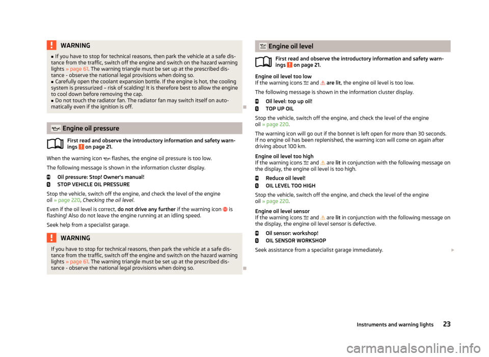
Engine oil pressure
First read and observe the introductory information and safety warn-
ings
on page 21.
When the warning icon
flashes, the engine oil pressure is too low.
The following message is shown in the information cluster display. Oil pressure: Stop! Owner's manual!
STOP VEHICLE OIL PRESSURE
Stop the vehicle, switch off the engine, and check the level of the engine
oil » page 220 , Checking the oil level .
Even if the oil level is correct, do not drive any further if the warning icon
is
flashing! Also do not leave the engine running at an idling speed.
Seek help from a specialist garage.
WARNINGIf you have to stop for technical reasons, then park the vehicle at a safe dis-
tance from the traffic, switch off the engine and switch on the hazard warning
lights » page 61 . The warning triangle must be set up at the prescribed dis-
tance - observe the national legal provisions when doing so.
Engine oil level
First read and observe the introductory information and safety warn-
ings
on page 21.
Engine oil level too low
If the warning icons and are lit , the engine oil level is too low.
The following message is shown in the information cluster display. Oil level: top up oil!
TOP UP OIL
Stop the vehicle, switch off the engine, and check the level of the engine
oil » page 220 .
The warning icon will go out if the bonnet is left open for more than 30 seconds.
If no engine oil has been replenished, the warning icon will come on again after
driving about 100 km.
Engine oil level too high
If the warning icons
and
are lit in conjunction with the following message on
the display, the engine oil level is too high.
Reduce oil level!
OIL LEVEL TOO HIGH
Stop the vehicle, switch off the engine, and check the level of the engine
oil » page 220 .
Engine oil level sensor
If the warning icons
and
are lit in conjunction with the following message on
the display, the engine oil level sensor is defective.
Oil sensor: workshop!
OIL SENSOR WORKSHOP
Seek assistance from a specialist garage immediately.
23Instruments and warning lights
Page 115 of 287
WARNINGNever leave recirculated air mode switched on over a longer period of time, as
“stale air” can cause driver and passenger fatigue, reduce attention levels and
also cause the windows to mist up. The risk of having an accident increases.
Switch off recirculated air mode as soon as the windows start to mist up.
Climatronic (automatic air conditioning system)
Introduction
This chapter contains information on the following subjects:
Control elements
112
Automatic mode
113
Switching the cooling system on/off
113
Setting temperature
113
Automatic recirculation mode
114
Controlling blower
114
Defrosting windscreen
115
The Climatronic in automatic mode ensures the best-possible setting of the tem-
perature of the outflowing air, the blower stage and air distribution.
The system also takes sunlight into account, which eliminates the need to alterthe settings manually.
The cooling system only operates if the following conditions are met. The cooling system is switched on » page 112, Control elements .
The engine is running.
The outside temperature above approx. +2 °C.
The cooling system is switched off at a high coolant temperature in order to pro-
vide cooling at a high load of the engine.
Note
We recommend that you have Climatronic cleaned by a specialist garage once ev-
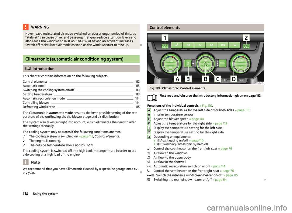
ery year.Control elementsFig. 110
Climatronic: Control elements
First read and observe the introductory information given on page 112.
Functions of the individual controls » Fig. 110 .
Adjust the temperature for the left side or for both sides » page 113
Interior temperature sensor
Adjust the blower speed » page 114
Adjust the temperature for the right side » page 113
Display the temperature setting for the left side
Display the temperature setting for the right side
Depending on equipment:
›
Aux. heating on/off » page 116
›
Switching Climatronic system off
Control the seat heater on the front left seat » page 76
Air flow to the windows
Air flow to the upper body
Air flow in the footwell
Automatic recirculation switch on or off » page 114
Control the seat heater on the front right seat » page 76
Switch the intensive windscreen heater on/off » page 115
Switching the rear window heater on/off » page 64
ABCD123112Using the system
Page 118 of 287
Defrosting windscreenFirst read and observe the introductory information given on page 112.
Switching on/off
›
Press the symbol button » Fig. 110 on page 112.
›
Press the symbol button again or press the symbol button .
More air flows out of the air outlet vents 1 » Fig. 106 on page 107. The tempera-
ture control is controlled automatically.
Auxiliary heating (auxiliary heating and ventilation)
Introduction
This chapter contains information on the following subjects:
Switching on/off
116
Radio remote control
116
Conditions for the functioning of auxiliary heating (Aux. heating and ventilation),
hereinafter referred to only as auxiliary heating (Aux. heating).
The charge state of the vehicle battery is sufficient.
The fuel supply is adequate (the warning icon
is not lit in the display of the
instrument cluster).
Auxiliary ventilation
The auxiliary ventilation enables fresh air to flow into the vehicle interior by
switching off the engine, whereby the interior temperature is effectively de-
creased (e.g. with the vehicle parked in the sun).
Auxiliary heating (parking heating)
The auxiliary heating (parking heating) can be used when stationary, when the engine is switched off to preheat the vehicle and while driving (e.g. during the
heating phase of the engine).
The auxiliary heater (parking heater) functions in connection with the air-condi-
tioning system or Climatronic.
The auxiliary heating (parking heating) also warms up the engine.
The auxiliary heating (parking heating) warms up the coolant by combusting fuel
from the vehicle tank. The coolant heats air flowing into the passenger compart- ment (as long as the blower fan speed B
» Fig. 108 on page 108 or
C
» Fig. 110
on page 112 is not set to zero).
WARNING■ The auxiliary heater (independent vehicle heater) must never be operated in
closed rooms (e.g. garages) – risk of poisoning!■
The auxiliary heating (parking heating) must not be running during refuelling
– risk of fire.
■
The exhaust pipe of the auxiliary heating is located underneath the vehicle.
Therefore, if you wish to operate the auxiliary heating (parking heating), do
not park the vehicle in such a way that the exhaust gases can come into con-
tact with highly flammable materials (e.g. dry grass) or easily inflammable sub-
stances (e.g. spilt fuel) – risk of fire.
CAUTION
■ The running auxiliary heating (parking heating) consumes fuel from the vehicle
tank and automatically controls the filling level. If only a low quantity of fuel is
present in the fuel tank, the auxiliary heater switches itself off.■
The exhaust pipe of the auxiliary heating, which is located underneath the vehi-
cle, must not be clogged up and the exhaust flow must not be blocked.
■
If the auxiliary heating is running, the vehicle battery discharges. If the auxiliary
heating and ventilation has been operated several times over a longer period, the
vehicle must be driven a few kilometres in order to recharge the vehicle battery.
Note
■ The auxiliary heating (aux. heating) switches on the blower B » Fig. 108 on
page 108 or C » Fig. 110 on page 112 only if it has achieved a coolant temperature
of approx. 50 °C.■
At low outside temperatures, this can result in a formation of water vapour in
the area of the engine compartment. This is quite normal and is not an operating problem.
■
The air inlet in front of the windscreen must be free of e.g. ice, snow or leaves
to ensure that the auxiliary heating and cooling system operates properly.
■
So that warm air can flow into the vehicle interior after switching on the auxili-
ary heating, you must maintain the comfort temperature normally selected by
you, leave the fan switched on and leave the air outlet vents in an open position.
It is recommended to put the air flow in the position or .
115Heating and air-conditioning
Page 119 of 287
Switching on/offFig. 111
Button for switching on/off the system directly on the operating
part of the air conditioning/Climatronic
First read and observe the introductory information and safety warn-ings
on page 115.
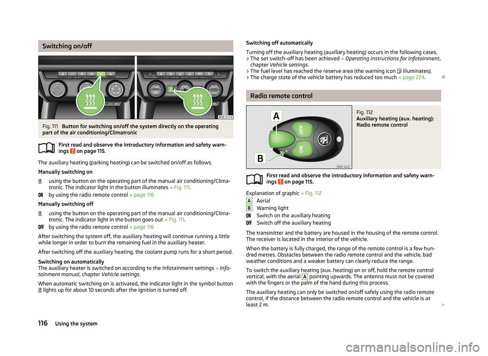
The auxiliary heating (parking heating) can be switched on/off as follows.
Manually switching on using the button on the operating part of the manual air conditioning/Clima-
tronic. The indicator light in the button illuminates » Fig. 111.
by using the radio remote control » page 116
Manually switching off
using the button on the operating part of the manual air conditioning/Clima-
tronic. The indicator light in the button goes out » Fig. 111.
by using the radio remote control » page 116
After switching the system off, the auxiliary heating will continue running a little
while longer in order to burn the remaining fuel in the auxiliary heater.
After switching off the auxiliary heating, the coolant pump runs for a short period.
Switching on automatically
The auxiliary heater is switched on according to the Infotainment settings » Info-
tainment manual , chapter Vehicle settings .
When automatic switching on is activated, the indicator light in the symbol button lights up for about 10 seconds after the ignition is turned off.
Switching off automatically
Turning off the auxiliary heating (auxiliary heating) occurs in the following cases. › The set switch-off has been achieved
» Operating instructions for Infotainment ,
chapter Vehicle settings .
› The fuel level has reached the reserve area (the warning icon
illuminates).
› The charge state of the vehicle battery has reduced too much
» page 224.
Radio remote control
Fig. 112
Auxiliary heating (aux. heating):
Radio remote control
First read and observe the introductory information and safety warn-
ings on page 115.
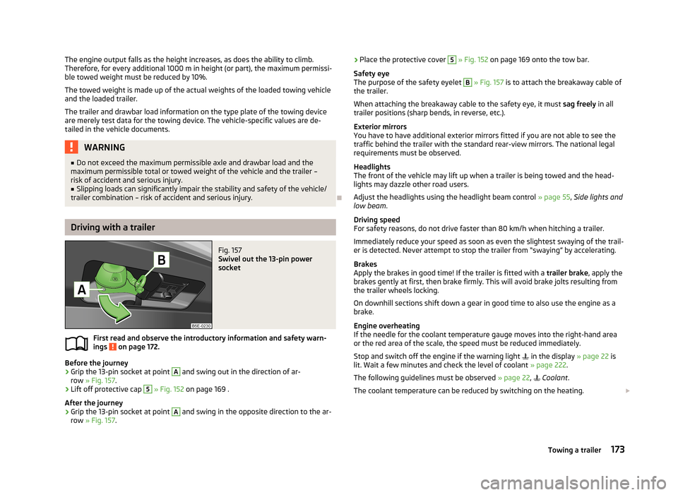
Explanation of graphic » Fig. 112
Aerial
Warning light
Switch on the auxiliary heating
Switch off the auxiliary heating
The transmitter and the battery are housed in the housing of the remote control. The receiver is located in the interior of the vehicle.
When the battery is fully charged, the range of the remote control is a few hun-
dred metres. Obstacles between the radio remote control and the vehicle, bad
weather conditions and a weaker battery can clearly reduce the range.
To switch the auxiliary heating (aux. heating) on or off, hold the remote control
vertical, with the aerial
A
pointing upwards. The antenna must not be covered
with the fingers or the palm of the hand during this process.
The auxiliary heating can only be switched on/off safely using the radio remote control, if the distance between the radio remote control and the vehicle is at
least 2 m.
AB116Using the system
Page 176 of 287
The engine output falls as the height increases, as does the ability to climb.
Therefore, for every additional 1000 m in height (or part), the maximum permissi- ble towed weight must be reduced by 10%.
The towed weight is made up of the actual weights of the loaded towing vehicleand the loaded trailer.
The trailer and drawbar load information on the type plate of the towing device are merely test data for the towing device. The vehicle-specific values are de-
tailed in the vehicle documents.WARNING■ Do not exceed the maximum permissible axle and drawbar load and the
maximum permissible total or towed weight of the vehicle and the trailer –
risk of accident and serious injury.■
Slipping loads can significantly impair the stability and safety of the vehicle/
trailer combination – risk of accident and serious injury.
Driving with a trailer
Fig. 157
Swivel out the 13-pin power
socket
First read and observe the introductory information and safety warn- ings on page 172.
Before the journey
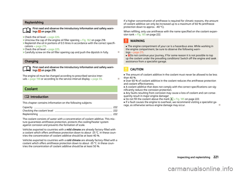
›
Grip the 13-pin socket at point
A
and swing out in the direction of ar-
row » Fig. 157 .
›
Lift off protective cap
5
» Fig. 152 on page 169 .
After the journey
›
Grip the 13-pin socket at point
A
and swing in the opposite direction to the ar-
row » Fig. 157 .
›Place the protective cover 5
» Fig. 152 on page 169 onto the tow bar.
Safety eye
The purpose of the safety eyelet B
» Fig. 157 is to attach the breakaway cable of
the trailer.
When attaching the breakaway cable to the safety eye, it must sag freely in all
trailer positions (sharp bends, in reverse, etc.).
Exterior mirrors
You have to have additional exterior mirrors fitted if you are not able to see the
traffic behind the trailer with the standard rear-view mirrors. The national legal requirements must be observed.
Headlights
The front of the vehicle may lift up when a trailer is being towed and the head-
lights may dazzle other road users.
Adjust the headlights using the headlight beam control » page 55, Side lights and
low beam .
Driving speed
For safety reasons, do not drive faster than 80 km/h when hitching a trailer.
Immediately reduce your speed as soon as even the slightest swaying of the trail- er is detected. Never attempt to stop the trailer from “swaying” by accelerating.
Brakes
Apply the brakes in good time! If the trailer is fitted with a trailer brake, apply the
brakes gently at first, then brake firmly. This will avoid brake jolts resulting from
the trailer wheels locking.
On downhill sections shift down a gear in good time to also use the engine as a
brake.
Engine overheating
If the needle for the coolant temperature gauge moves into the right-hand area
or the red area of the scale, the speed must be reduced immediately.
Stop and switch off the engine if the warning light
in the display » page 22 is
lit. Wait a few minutes and check the level of coolant » page 222.
The following guidelines must be observed » page 22,
Coolant .
The coolant temperature can be reduced by switching on the heating.
173Towing a trailer
Page 224 of 287
ReplenishingFirst read and observe the introductory information and safety warn-
ings
on page 219.
›
Check the oil level » page 220.
›
Unscrew the cap of the engine oil filler opening » Fig. 182 on page 218.
›
Replenish the oil in portions of 0.5 litres in accordance with the correct specifi-
cations » page 219 .
›
Check the oil level » page 220.
›
Carefully screw on the oil filler opening cap and push the dipstick in fully.
Changing
First read and observe the introductory information and safety warn-ings
on page 219.
The engine oil must be changed according to prescribed service inter-vals » page 198 or according to the service interval display » page 33.
Coolant
Introduction
This chapter contains information on the following subjects:
Capacity
222
Checking the coolant level
222
Replenishing
222
The coolant consists of water with a concentration of coolant additive. This mix-
ture guarantees antifreeze protection, protects the cooling/heater system
against corrosion and prevents the formation of scale.
Vehicles exported to countries with a mild climate are already factory-filled with
a coolant which offers antifreeze protection down to about -25 ℃. In these coun-
tries the concentration of coolant additive should be at least 40 %.
Vehicles exported to countries with a cold climate are already factory-filled with a
coolant which offers antifreeze protection down to about -35 °C. In these coun-
tries the concentration of coolant additive should be at least 50 %.
If a higher concentration of antifreeze is required for climatic reasons, the amount
of coolant additive can only be increased up to a maximum of 60 % (antifreeze
protection down to approx. -40 °C).
When refilling, only use antifreeze with the name specified on the coolant expan-
sion tank » Fig. 185 on page 222.WARNING■
The engine compartment of your car is a hazardous area. While working in
the engine compartment, be sure to observe the following warn- ings » page 215 .■
Do not continue your journey, if for some reason it is not possible to top
up the coolant under the prevailing conditions! Switch off the engine and seek
assistance from a specialist garage.
CAUTION
■ The amount of coolant additive in the coolant must never be allowed to be less
than 40 %.■
Over 60 % of coolant additive in the coolant reduces the antifreeze protection
and coolant effectiveness.
■
A coolant additive that does not comply with the correct specifications can sig-
nificantly reduce the corrosion protection.
■
Any faults resulting from corrosion may cause a loss of coolant and can conse-
quently result in major engine damage!
■
Do not fill the coolant above the mark
A
» Fig. 185 on page 222.
■
If a fault causes the engine to overheat, we recommend visiting a specialist ga-
rage, as otherwise serious engine damage may occur.
221Inspecting and replenishing