stop start SKODA OCTAVIA 2013 3.G / (5E) Owner's Manual
[x] Cancel search | Manufacturer: SKODA, Model Year: 2013, Model line: OCTAVIA, Model: SKODA OCTAVIA 2013 3.G / (5E)Pages: 287, PDF Size: 18.55 MB
Page 6 of 287
Table of Contents
Materials defect liability and ŠKODA warranty for
new cars5
Mobility warranty and ŠKODA extended
warranty
6
Abbreviations
Using the system
Cockpit
9
Overview
8
Instruments and warning lights
11
Instrument cluster
11
Warning lights
15
Warning icons in the display
21
Information system
26
Driver information system
26
Driving data (Multifunction display)
29
MAXI DOT display
31
Service interval display
33
Unlocking and opening
35
Unlocking and locking
35
KESSY
41
Anti-theft alarm system
42
Luggage compartment lid
43
Electric luggage compartment lid (Octavia
Estate)
44
Electrical power windows
47
Panoramic sliding/tilting roof (Octavia)
50
Panoramic sliding/tilting roof (Octavia Estate)
51
Lights and visibility
54
Lights
54
Interior lights
61Visibility64Windscreen wipers and washers65
Rear mirror
68
Seats and useful equipment
71
Adjusting the seats
71
Seat features
76
Practical equipment
79
Luggage compartment
91
Variable loading floor in the luggage
compartment (Estate)
99
Net partition (Octavia Estate)
101
Roof rack system
103
Heating and air-conditioning
106
Heating, ventilation, cooling
106
Heating
108
Air conditioning system (manual air conditioning
system)
110
Climatronic (automatic air conditioning system)
112
Auxiliary heating (auxiliary heating and ventilation)
115
Driving
Starting-off and Driving
118
Steering
118
Starting and stopping the engine using the key
119
Starting and stopping the engine - KESSY
121
Brakes
124
Manual shifting of gears and pedals
126
Automatic transmission
126
Running in
130
Economical driving and environmental
sustainability
131
Avoiding damage to your vehicle
135
Driving abroad
136Assist systems137Brake assist systems137
Parking aid
140
Park assist
142
Cruise Control System
146
Adaptive Cruise Control (ACC)
148
Area monitoring system (Front Assist)
154
START-STOP
158
Driving mode
161
ProActive passenger protection
163
Lane Assist
164
Traffic sign recognition
166
Fatigue detection (break recommendation)
168
Towing a trailer
169
Towing device
169
Trailer
172
Safety
Passive Safety
176
General information
176
Correct seated position
177
Seat belts
180
Using seat belts
180
Inertia reel and belt pretensioners
183
Airbag system
185
Description of the airbag system
185
Airbag overview
186
Deactivating airbags
190
Transporting children safely
193
Child seat
193
Fastening elements
1963Table of Contents
Page 12 of 287
Using the system
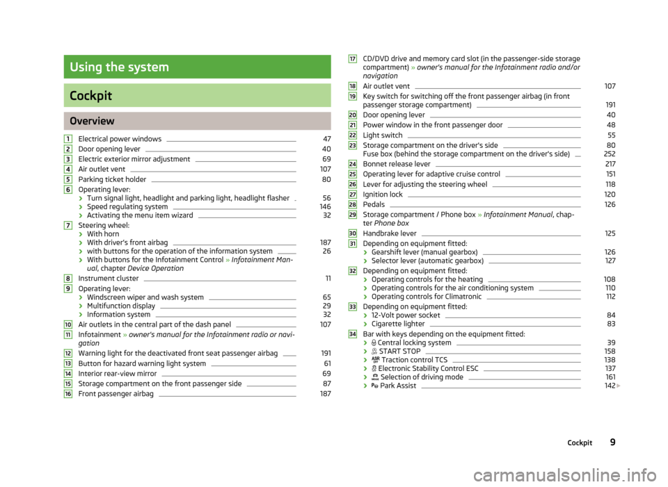
Cockpit
OverviewElectrical power windows
47
Door opening lever
40
Electric exterior mirror adjustment
69
Air outlet vent
107
Parking ticket holder
80
Operating lever:
› Turn signal light, headlight and parking light, headlight flasher
56
›
Speed regulating system
146
›Activating the menu item wizard
32
Steering wheel:
› With horn
› With driver’s front airbag
187
›
with buttons for the operation of the information system
26
›With buttons for the Infotainment Control
» Infotainment Man-
ual , chapter Device Operation
Instrument cluster
11
Operating lever:
› Windscreen wiper and wash system
65
›Multifunction display
29
›
Information system
32
Air outlets in the central part of the dash panel
107
Infotainment
» owner's manual for the Infotainment radio or navi-
gation
Warning light for the deactivated front seat passenger airbag
191
Button for hazard warning light system
61
Interior rear-view mirror
69
Storage compartment on the front passenger side
87
Front passenger airbag
18712345678910111213141516CD/DVD drive and memory card slot (in the passenger-side storage compartment) » owner's manual for the Infotainment radio and/or
navigation
Air outlet vent107
Key switch for switching off the front passenger airbag (in front passenger storage compartment)
191
Door opening lever
40
Power window in the front passenger door
48
Light switch
55
Storage compartment on the driver's side
80
Fuse box (behind the storage compartment on the driver's side)
252
Bonnet release lever
217
Operating lever for adaptive cruise control
151
Lever for adjusting the steering wheel
118
Ignition lock
120
Pedals
126
Storage compartment / Phone box » Infotainment Manual , chap-
ter Phone box
Handbrake lever
125
Depending on equipment fitted:
› Gearshift lever (manual gearbox)
126
›
Selector lever (automatic gearbox)
127
Depending on equipment fitted:
› Operating controls for the heating
108
›
Operating controls for the air conditioning system
110
›Operating controls for Climatronic
112
Depending on equipment fitted:
› 12-Volt power socket
84
›
Cigarette lighter
83
Bar with keys depending on the equipment fitted:
›
Central locking system
39
›
START STOP
158
›
Traction control TCS
138
›
Electronic Stability Control ESC
137
›
Selection of driving mode
161
›
Park Assist
142
1718192021222324252627282930313233349Cockpit
Page 20 of 287
Stop the vehicle, switch off the engine, and check the level of the brake flu-
id » page 223 » .
If the warning light lights up together with the warning light , there is a
problem with the ABS.WARNING■ If you have to stop for technical reasons, then park the vehicle at a safe dis-
tance from the traffic, switch off the engine and switch on the hazard warning lights » page 61 . The warning triangle must be set up at the prescribed dis-
tance - observe the national legal provisions when doing so.■
If the warning light is displayed simultaneously with warning light
» page 18 , Antilock brake system (ABS) , do not continue your jour-
ney! Seek help from a specialist garage.
■
A fault to the braking system can increase the vehicle's braking distance -
risk of accident!
Seat belt warning light
First read and observe the introductory information and safety warn-ings
on page 15.
The warning light
comes on after the ignition is switched on as a reminder for
the driver and front passenger to fasten the seat belt.
The warning light
goes out if the driver or front passenger has fastened their
seat belt.
If the driver or front passenger has not fastened their seat belt and the vehicle
speed is more than 30 km/h, the warning light
flashes and you will hear an
acoustic signal.
If the seat belt is not fastened by the driver or front passenger during the next
approx. 2 seconds, the warning signal is deactivated and the warning light
lights up permanently.
Further information » page 180, Seat belts .
Power steering
First read and observe the introductory information and safety warn-
ings
on page 15.
If the warning light lights up, this indicates a partial failure of the power steer-
ing and the steering forces can be greater. Seek assistance from a specialist ga-
rage immediately.
If the warning light lights up, this indicates a complete failure of the power
steering and the steering assist has failed (significantly higher steering forces).
Seek assistance from a specialist garage immediately.
Further information » page 119, Power steering .
Note
If the vehicle's battery has been disconnected and reconnected, the warning light
comes on after switching on the ignition. The warning light should go out after
driving a short distance. If, after starting the engine again and a short drive, the
yellow warning light does not go out, there is a fault in the system. Seek assis-
tance from a specialist garage immediately.
Traction Control System (ASR)
First read and observe the introductory information and safety warn-
ings
on page 15.
If your vehicle is equipped with the ESC system, the TCS is part of the
ESC » page 137 .
The warning light flashes
to show that the ASR is currently operating.
If the warning light
illuminates , there is a fault in the ASR.
The following message is shown in the information cluster display. Error: traction control
ASR ERROR
Seek assistance from a specialist garage immediately. If the warning light
comes on after starting the engine, the TCS may be switch-
ed off for technical reasons.
› Switch the ignition off and on again.
17Instruments and warning lights
Page 21 of 287
If the warning light does not illuminates after you switch the engine back on,
the ASR is fully functional again.
Further information » page 137, Electronic Stability Control (ESC) and » page 138 ,
Traction Control System (TCS) .
Note
If the vehicle battery has been disconnected and then reconnected, the indicator
light comes on after switching on the ignition. If the indicator light does not go
out after moving a short distance, this means that there is an error in the system. Seek assistance from a specialist garage immediately.
Traction control system (TCS) off
First read and observe the introductory information and safety warn-ings
on page 15.
If the warning light
is lit, the TCS is off.
The following message is shown in the information cluster display.
Traction control (ASR) deactivated.
ASR OFF
Further information » page 138, Traction Control System (TCS) .
Electronic Stability Control (ESC)
First read and observe the introductory information and safety warn-
ings
on page 15.
The warning light
flashes to show that the ESC is currently operating.
If the warning light
illuminates , there is a fault in the ESC.
The following message is shown in the information cluster display. Error: stabilisation control (ESC)
ESC ERROR
Seek assistance from a specialist garage immediately. If the warning light
comes on after starting the engine, the ESC system may be
switched off for technical reasons.
› Switch the ignition off and on again.
If the indicator light does not illuminate after you switch the engine back on,
the ESR is fully functional again.
Further information » page 137, Electronic Stability Control (ESC) .
Note
If the vehicle battery has been disconnected and then reconnected, the indicator
light comes on after switching on the ignition. If the indicator light does not go
out after moving a short distance, this means that there is an error in the system. Seek assistance from a specialist garage immediately.
Antilock brake system (ABS)
First read and observe the introductory information and safety warn-
ings
on page 15.
If the warning light
lights up, there is a fault in the ABS.
The following message is shown in the information cluster display.
Error: ABS
ABS ERROR
The vehicle will only be braked by the normal brake system without the ABS.
Seek assistance from a specialist garage immediately. Further information » page 138, Antilock Braking System (ABS) .
WARNING■
If you have to stop for technical reasons, then park the vehicle at a safe dis-
tance from the traffic, switch off the engine and switch on the hazard warning lights » page 61 . The warning triangle must be set up at the prescribed dis-
tance - observe the national legal provisions when doing so.■
If the warning light is displayed simultaneously with warning light ,
do not continue your journey! Seek help from a specialist garage.
■
A fault to the ABS system or the braking system can increase the vehicle's
braking distance – risk of accident!
18Using the system
Page 24 of 287
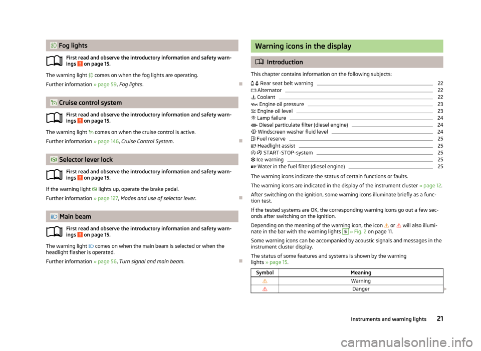
Fog lightsFirst read and observe the introductory information and safety warn-
ings
on page 15.
The warning light comes on when the fog lights are operating.
Further information » page 59, Fog lights .
Cruise control system
First read and observe the introductory information and safety warn-
ings
on page 15.
The warning light
comes on when the cruise control is active.
Further information » page 146, Cruise Control System .
Selector lever lock
First read and observe the introductory information and safety warn-
ings
on page 15.
If the warning light
lights up, operate the brake pedal.
Further information » page 127, Modes and use of selector lever .
Main beam
First read and observe the introductory information and safety warn-ings
on page 15.
The warning light
comes on when the main beam is selected or when the
headlight flasher is operated.
Further information » page 56, Turn signal and main beam .
Warning icons in the display
Introduction
This chapter contains information on the following subjects:
Rear seat belt warning
22
Alternator
22
Coolant
22
Engine oil pressure
23
Engine oil level
23
Lamp failure
24
Diesel particulate filter (diesel engine)
24
Windscreen washer fluid level
24
Fuel reserve
25
Headlight assist
25
START-STOP-system
25
Ice warning
25
Water in the fuel filter (diesel engine)
25
The warning icons indicate the status of certain functions or faults.
The warning icons are indicated in the display of the instrument cluster » page 12.
After switching on the ignition, some warning icons illuminate briefly as a func- tion test.
If the tested systems are OK, the corresponding warning icons go out a few sec-
onds after switching on the ignition.
Depending on the meaning of the warning icon, the icon
or
will also illumi-
nate in the bar with the warning lights
5
» Fig. 2 on page 11.
Some warning icons can be accompanied by acoustic signals and messages in the
instrument cluster display.
The status of some features and systems is shown by the warning
lights » page 15 .
SymbolMeaningWarningDanger 21Instruments and warning lights
Page 28 of 287
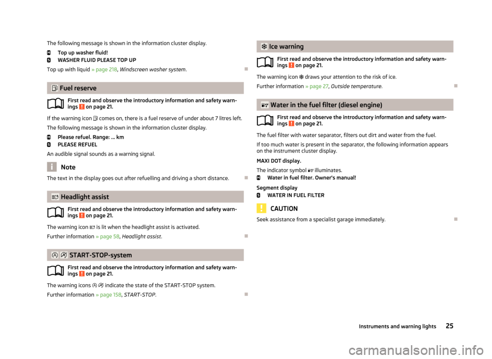
The following message is shown in the information cluster display.Top up washer fluid!
WASHER FLUID PLEASE TOP UP
Top up with liquid » page 218, Windscreen washer system .
Fuel reserve
First read and observe the introductory information and safety warn-ings
on page 21.
If the warning icon comes on, there is a fuel reserve of under about 7 litres left.
The following message is shown in the information cluster display. Please refuel. Range: ... km
PLEASE REFUEL
An audible signal sounds as a warning signal.
Note
The text in the display goes out after refuelling and driving a short distance.
Headlight assist
First read and observe the introductory information and safety warn-ings
on page 21.
The warning icon
is lit when the headlight assist is activated.
Further information » page 58, Headlight assist .
START-STOP-system
First read and observe the introductory information and safety warn- ings
on page 21.
The warning icons
indicate the state of the START-STOP system.
Further information » page 158, START-STOP .
Ice warning
First read and observe the introductory information and safety warn-ings
on page 21.
The warning icon draws your attention to the risk of ice.
Further information » page 27, Outside temperature .
Water in the fuel filter (diesel engine)
First read and observe the introductory information and safety warn-ings
on page 21.
The fuel filter with water separator, filters out dirt and water from the fuel.
If too much water is present in the separator, the following information appears on the instrument cluster display.
MAXI DOT display.
The indicator symbol illuminates.
Water in fuel filter. Owner's manual!
Segment display WATER IN FUEL FILTER
CAUTION
Seek assistance from a specialist garage immediately.
25Instruments and warning lights
Page 35 of 287
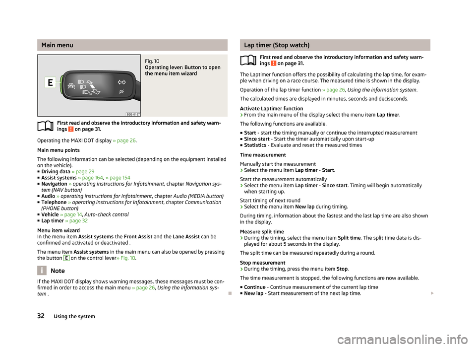
Main menuFig. 10
Operating lever: Button to open
the menu item wizard
First read and observe the introductory information and safety warn-
ings on page 31.
Operating the MAXI DOT display » page 26.
Main menu points
The following information can be selected (depending on the equipment installed on the vehicle).
■ Driving data » page 29
■ Assist systems » page 164 , » page 154
■ Navigation » operating instructions for Infotainment , chapter Navigation sys-
tem (NAV button)
■ Audio » operating instructions for Infotainment , chapter Audio (MEDIA button)
■ Telephone » operating instructions for Infotainment , chapter Communication
(PHONE button)
■ Vehicle » page 14 , Auto-check control
■ Lap timer » page 32
Menu item wizard
In the menu item Assist systems the Front Assist and the Lane Assist can be
confirmed and activated or deactivated .
The menu item Assist systems in the main menu can also be opened by pressing
the button
E
on the control lever » Fig. 10.
Note
If the MAXI DOT display shows warning messages, these messages must be con-
firmed in order to access the main menu » page 26, Using the information sys-
tem .
Lap timer (Stop watch)
First read and observe the introductory information and safety warn-ings
on page 31.
The Laptimer function offers the possibility of calculating the lap time, for exam-
ple when driving on a race course. The measured time is shown in the display.
Operation of the lap timer function » page 26, Using the information system .
The calculated times are displayed in minutes, seconds and deciseconds.
Activate Laptimer function › From the main menu of the display select the menu item
Lap timer.
The following functions are available. ■ Start - start the timing manually or continue the interrupted measurement
■ Since start - Start the timer automatically upon start-up
■ Statistics - Evaluate and reset the measured times
Time measurement
Manually start the measurement › Select the menu item
Lap timer - Start .
Start the measurement automatically
› Select the menu item
Lap timer - Since start . Timing will begin automatically
when starting up.
Start timing of next round
› Select the menu item
New lap during timing.
During timing, information about the fastest and the last lap time are also shown
in the display.
Measure split time
› During the timing, select the menu item
Split time. The split time data is dis-
played for about 5 seconds in the display.
The split time can be measured repeatedly during a round.
Stop measurement › During the timing, press the menu item
Stop.
The time measurement is stopped, the following functions are now available.
■ Continue - Continue measurement of the current lap time
■ New lap - Start measurement of the next lap time.
32Using the system
Page 36 of 287
■Abort lap - Cancel the timer (the aborted lap time is not stored)
■ Hang up - End timing (the aborted lap time is stored)
Evaluate recorded times
› Select the menu item
Lap timer - Statistics .
The following information is displayed. › Fastest:
- The fastest lap
› Slowest:
- The slowest lap
› Average:
- The average lap time
› Overall time:
- The total of all the lap times
Reset measured times
› Select the menu item
Lap timer - Statistics - Reset .WARNING■
Concentrate fully at all times on your driving! As the driver, you are fully re-
sponsible for the operation of your vehicle.■
Only use the Lap timer system when you are in any traffic situation where
you have full control over the vehicle.
Note
■ The system allows the measurement of up to 11 lap times.■The measurement of single lap time is stopped after 99 h, 59 min and 59 sec.
After this time has been reached, measuring the new lap starts automatically.■
The measured times cannot be reset individually.
■
If the measured times are not reset, then these are stored even after turning
off the ignition.
Service interval display
Introduction
This chapter contains information on the following subjects:
Service messages
33
Resetting Service Interval Display
34
The service due date is automatically displayed on the display and this informa- tion can be displayed manually at any time if necessary.
Note■ Information is retained in the Service Interval Display even after the vehicle bat-
tery is disconnected.■
If the instrument cluster is exchanged after a repair, the correct values must be
entered in the counter for the Service Interval Display. This work is carried out by a specialist garage.
■
In some national versions the displays appear in the Imperial system of meas-
urement.
■
For more information on the service intervals, see » page 198, Service intervals .
Service messages
First read and observe the introductory information given on page 33.
Messages before reaching the scheduled service dateBefore reaching the service date, the icon
appears in the display after the igni-
tion is switched on, as well as the following message for example.
Oil change in ... days
OIL CHANGE IN ... DAYS
or
Inspection in ... days
INSPECT_ IN ...DAYS
The kilometre indicator or the days indicator reduces in steps of 100 km or, where
applicable, days until the service due date is reached.
Messages upon reaching scheduled service date
Once the service interval is reached, the icon
appears in the display after the
ignition is switched on, as well as the following message for example.
Oil change now!
OIL CHANGE NOW
or Inspection now!
INSPECTION NOW
or
33Information system
Page 39 of 287
Vehicle keyFig. 11
Key: without/with remote control
First read and observe the introductory information and safety warn- ings
on page 35.
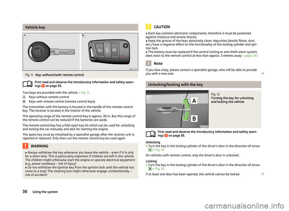
Two keys are provided with the vehicle » Fig. 11.
Keys without remote control
Keys with remote control (remote control keys)
The transmitter with the battery is housed in the handle of the remote control key. The receiver is located in the interior of the vehicle.
The operating range of the remote control key is approx. 30 m. But this range ofthe remote control can be reduced if the batteries are weak.
The remote control key has a fold-open key bit which can be used for unlocking
and locking the car manually and also for starting the engine.
The spare key must by initialised by a specialist garage after the receiver unit is repaired or replaced. Only then can the remote control key be used again.
WARNING■ Always withdraw the key whenever you leave the vehicle – even if it is only
for a short time. This is particularly important if children are left in the vehicle.
The children might otherwise start the engine or operate electrical equipment
(e.g. power windows) – risk of injury!■
Do not withdraw the ignition key from the ignition lock until the vehicle has
come to a stop! The steering lock might otherwise engage unintentionally – risk of accident!
CAUTION■ Each key contains electronic components; therefore it must be protected
against moisture and severe shocks.■
Keep the groove of the keys absolutely clean. Impurities (textile fibres, dust,
etc.) have a negative effect on the functionality of the locking cylinder and igni-
tion lock.
■
The battery must be replaced if the central locking or anti-theft alarm system
does react to the remote control at less than approx. 3 metres away » page 247.
Note
If you lose a key, please contact a specialist garage, who will be able to provide
you with a new one.
Unlocking/locking with the key
Fig. 12
Turning the key for unlocking
and locking the vehicle
First read and observe the introductory information and safety warn-
ings on page 35.
Unlocking
›
Turn the key in the locking cylinder of the driver's door in the direction of arrow
A
» Fig. 12 .
On vehicles with remote control, only the driver's door is unlocked.
Locking
›
Turn the key in the locking cylinder of the driver's door in the direction of arrow
B
» Fig. 12 .
If at least one door has been opened, the vehicle cannot be locked.
36Using the system
Page 46 of 287
Interior monitor and towing protectionFig. 18
Button for interior monitor and
towing protection
First read and observe the introductory information and safety warn-
ings on page 42.
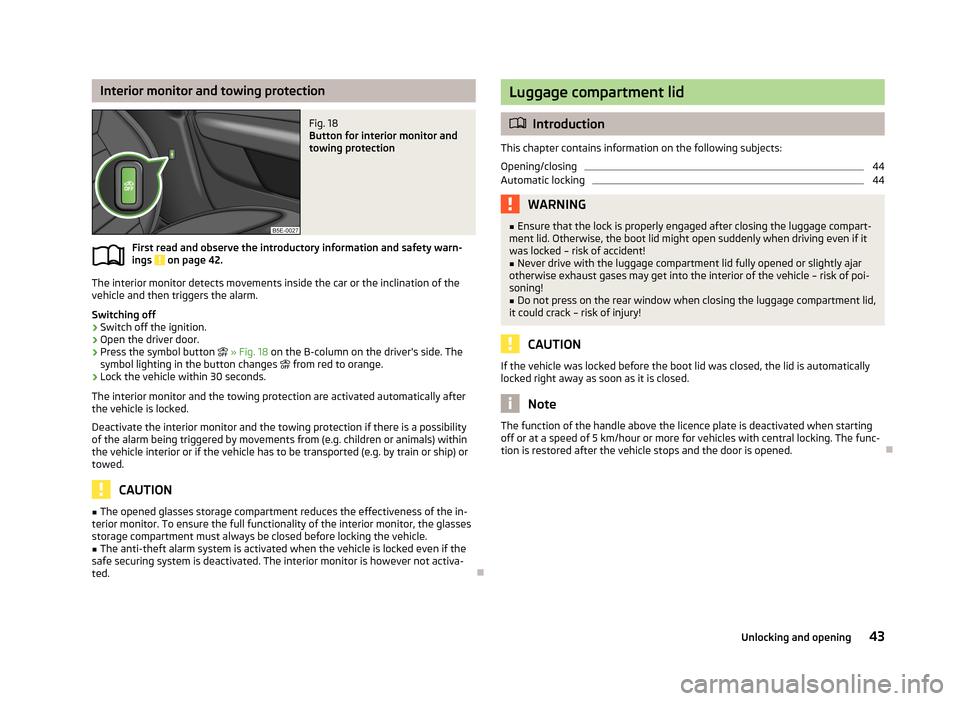
The interior monitor detects movements inside the car or the inclination of the
vehicle and then triggers the alarm.
Switching off
›
Switch off the ignition.
›
Open the driver door.
›
Press the symbol button
» Fig. 18 on the B-column on the driver's side. The
symbol lighting in the button changes
from red to orange.
›
Lock the vehicle within 30 seconds.
The interior monitor and the towing protection are activated automatically after
the vehicle is locked.
Deactivate the interior monitor and the towing protection if there is a possibility
of the alarm being triggered by movements from (e.g. children or animals) within
the vehicle interior or if the vehicle has to be transported (e.g. by train or ship) or towed.
CAUTION
■ The opened glasses storage compartment reduces the effectiveness of the in-
terior monitor. To ensure the full functionality of the interior monitor, the glasses storage compartment must always be closed before locking the vehicle.■
The anti-theft alarm system is activated when the vehicle is locked even if the
safe securing system is deactivated. The interior monitor is however not activa-
ted.
Luggage compartment lid
Introduction
This chapter contains information on the following subjects:
Opening/closing
44
Automatic locking
44WARNING■ Ensure that the lock is properly engaged after closing the luggage compart-
ment lid. Otherwise, the boot lid might open suddenly when driving even if it
was locked – risk of accident!■
Never drive with the luggage compartment lid fully opened or slightly ajar
otherwise exhaust gases may get into the interior of the vehicle – risk of poi-
soning!
■
Do not press on the rear window when closing the luggage compartment lid,
it could crack – risk of injury!
CAUTION
If the vehicle was locked before the boot lid was closed, the lid is automatically
locked right away as soon as it is closed.
Note
The function of the handle above the licence plate is deactivated when starting
off or at a speed of 5 km/hour or more for vehicles with central locking. The func-
tion is restored after the vehicle stops and the door is opened.
43Unlocking and opening