wheel SKODA OCTAVIA 2013 3.G / (5E) Owner's Manual
[x] Cancel search | Manufacturer: SKODA, Model Year: 2013, Model line: OCTAVIA, Model: SKODA OCTAVIA 2013 3.G / (5E)Pages: 287, PDF Size: 18.55 MB
Page 7 of 287
General Maintenance
Vehicle care198
Service intervals
198
Service work, adjustments and technical alterations
200
Washing your car
203
Taking care of your vehicle exterior
205
Taking care of the interior
208
Inspecting and replenishing
212
Fuel
212
Engine compartment
215
Engine oil
219
Coolant
221
Brake fluid
223
Vehicle battery
224
Wheels
228
Tyres and wheel rims
228
Winter operation
234
Do-it-yourself
Emergency equipment, and self-help
235
Emergency equipment
235
Changing a wheel
237
Tyre repair
240
Jump-starting
243
Towing the vehicle
244
Remote control
246
Emergency unlocking/locking
248
Replacing windscreen wiper blades
249
Fuses and light bulbs
251
Fuses
251
Bulbs
255Technical data
Technical data263
Vehicle data
263
Index
4Table of Contents
Page 12 of 287
Using the system
Cockpit
OverviewElectrical power windows
47
Door opening lever
40
Electric exterior mirror adjustment
69
Air outlet vent
107
Parking ticket holder
80
Operating lever:
› Turn signal light, headlight and parking light, headlight flasher
56
›
Speed regulating system
146
›Activating the menu item wizard
32
Steering wheel:
› With horn
› With driver’s front airbag
187
›
with buttons for the operation of the information system
26
›With buttons for the Infotainment Control
» Infotainment Man-
ual , chapter Device Operation
Instrument cluster
11
Operating lever:
› Windscreen wiper and wash system
65
›Multifunction display
29
›
Information system
32
Air outlets in the central part of the dash panel
107
Infotainment
» owner's manual for the Infotainment radio or navi-
gation
Warning light for the deactivated front seat passenger airbag
191
Button for hazard warning light system
61
Interior rear-view mirror
69
Storage compartment on the front passenger side
87
Front passenger airbag
18712345678910111213141516CD/DVD drive and memory card slot (in the passenger-side storage compartment) » owner's manual for the Infotainment radio and/or
navigation
Air outlet vent107
Key switch for switching off the front passenger airbag (in front passenger storage compartment)
191
Door opening lever
40
Power window in the front passenger door
48
Light switch
55
Storage compartment on the driver's side
80
Fuse box (behind the storage compartment on the driver's side)
252
Bonnet release lever
217
Operating lever for adaptive cruise control
151
Lever for adjusting the steering wheel
118
Ignition lock
120
Pedals
126
Storage compartment / Phone box » Infotainment Manual , chap-
ter Phone box
Handbrake lever
125
Depending on equipment fitted:
› Gearshift lever (manual gearbox)
126
›
Selector lever (automatic gearbox)
127
Depending on equipment fitted:
› Operating controls for the heating
108
›
Operating controls for the air conditioning system
110
›Operating controls for Climatronic
112
Depending on equipment fitted:
› 12-Volt power socket
84
›
Cigarette lighter
83
Bar with keys depending on the equipment fitted:
›
Central locking system
39
›
START STOP
158
›
Traction control TCS
138
›
Electronic Stability Control ESC
137
›
Selection of driving mode
161
›
Park Assist
142
1718192021222324252627282930313233349Cockpit
Page 29 of 287
Information system
Driver information system
Introduction
This chapter contains information on the following subjects:
Using the information system
26
Outside temperature
27
Gear recommendation
27
Door, luggage compartment or bonnet warning
28
Eco tips
28
Compass point display
28
The information system provides the driver with alerts and messages about in-
dividual vehicle systems. These alerts and messages appear in the instrument
cluster display
2
» Fig. 2 on page 11 (hereafter only in the display).
The information system provides the following information. › Outside temperature
» page 27.
› Recommended gear
» page 27.
›Door, boot lid and bonnet warning
» page 28.
› Eco tips
» page 28 .
› Compass display
» page 28.
› Driving data (multifunction display)
» page 29.
› Warning against excessive speeds
» page 31.
› Data relating to the Maxi DOT display
» page 32.
› To the lap timer function (stopwatch)
» page 32 .
› Service interval display
» page 33.
› Auto Check Control
» page 14.
› Warning icons
» page 21.
› Traffic sign recognition
» page 166.
› Fatigue detection
» page 168.
› Selector lever positions for an automatic gearbox
» page 127.
› Information and alerts in the Assist systems
» page 137.WARNINGConcentrate fully at all times on your driving! As the driver, you are fully re-
sponsible for the operation of your vehicle.
Using the information system
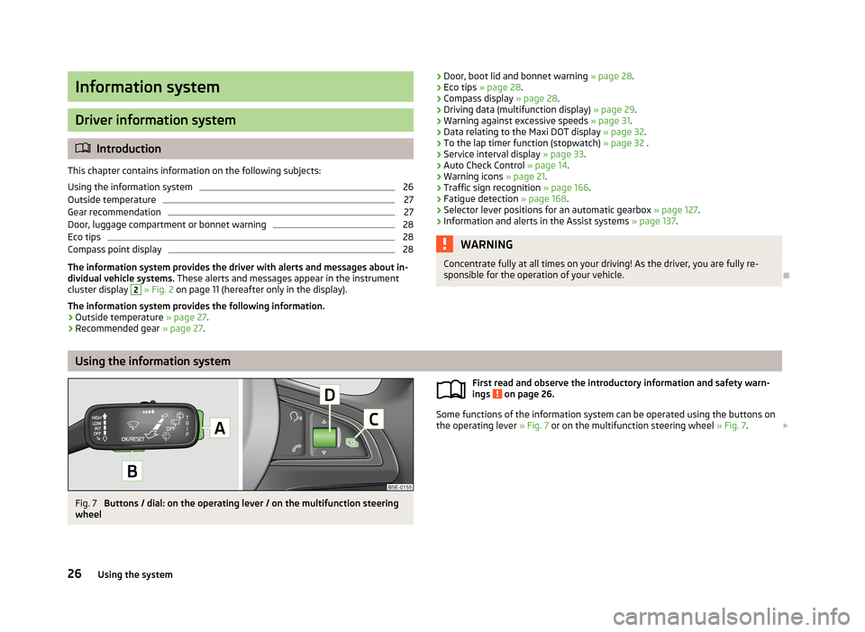
Fig. 7
Buttons / dial: on the operating lever / on the multifunction steering
wheel
First read and observe the introductory information and safety warn-
ings on page 26.
Some functions of the information system can be operated using the buttons on
the operating lever » Fig. 7 or on the multifunction steering wheel » Fig. 7.
26Using the system
Page 30 of 287
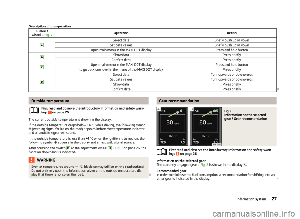
Description of the operationButton /
wheel » Fig. 7OperationActionASelect dataBriefly push up or downSet data valuesBriefly push up or downOpen main menu in the MAXI DOT displayPress and hold buttonBShow dataPress brieflyConfirm dataPress brieflyCOpen main menu in the MAXI DOT displayPress and hold buttonto go back one level in the menu of the MAXI DOT displayPress brieflyDSelect dataTurn upwards or downwardsSet data valuesTurn upwards or downwardsShow dataPress brieflyConfirm dataPress briefly
Outside temperature
First read and observe the introductory information and safety warn-ings
on page 26.
The current outside temperature is shown in the display.
If the outside temperature drops below +4 °C while driving, the following symbol
(warning signal for ice on the road) appears before the temperature indicator
and an audible signal will sound.
If the outside temperature is less than +4 °C when the ignition is turned on, the
following symbol appears in the display and an acoustic signal sounds.
After pressing the switch
B
or the adjustment wheel
D
» Fig. 7 on page 26, the
function shown last is indicated.
WARNINGEven at temperatures around +4 °C, black ice may still be on the road surface!
Do not only rely upon the information given on the outside temperature dis-
play that there is no ice on the road.
Gear recommendationFig. 8
Information on the selected
gear / Gear recommendation
First read and observe the introductory information and safety warn-
ings on page 26.
Information on the selected gear
The currently engaged gear » Fig. 8 is shown in the display
.
Recommended gear
In order to minimise the fuel consumption, a recommendation for shifting into an-
other gear is indicated in the display.
27Information system
Page 32 of 287
Driving data (Multifunction display)
Introduction
This chapter contains information on the following subjects:
Memory
29
Information overview
29
Warning at excessive speeds
31
The multifunction display only operates if the ignition is switched on.
After the ignition is switched on, the function that was last selected before
switching off the ignition is displayed.
Individual menu items can be shown or hidden in the Infotainment » Bedienung-
sanleitung Infotainment, chapter Vehicle settings (CAR button).
WARNINGConcentrate fully at all times on your driving! As the driver, you are fully re-
sponsible for the operation of your vehicle.
Note
In some national versions the displays appear in the Imperial system of measure-
ment.
Memory
First read and observe the introductory information and safety warn-
ings
on page 29.
The multifunction display is equipped with three automatic memories.
The display of the selected memory varies depending on vehicle equipment.
Since start (MAXI DOT display) or “1” (segment display)The memory collates the driving information from the moment the ignition isswitched on until it is switched off.
New data will also flow into the calculation of the current driving information if
the trip is continued within 2 hours after switching off the ignition.
If the trip is interrupted for more than 2 hours, the memory is automatically
erased.
Long-term (MAXI DOT display) or “2” (segment display)
The memory gathers driving information from any number of individual journeys
up to a total of 99 hours and 59 minutes driving or 9999 kilometres driven.
The memory is deleted when either of these limits is reached and the calculation
starts all over again.
Since refuel (MAXI DOT display) or “3” (segment display)
The memory gathers driving information since the last refuelling.
The memory is erased automatically the next time you fill up.
Select memory›
Select the corresponding element of the travel data » page 26, Using the infor-
mation system .
Confirm the element again to switch between the individual memories.
Resetting
›
Select the corresponding element of the travel data » page 26, Using the infor-
mation system .
›
Select the desired memory.
›
Press and hold button
B
or adjustment wheel
D
» Fig. 7 on page 26.
The following values of the selected memory are set to zero. › Average fuel consumption.
› Distance driven.
› Average speed.
› Driving time
Note
Disconnecting the vehicle battery will delete all memory data.
Information overview
First read and observe the introductory information and safety warn-
ings
on page 29.
The amount of information displayed may differ depending on the equipment.
29Information system
Page 58 of 287
Side lights and low beamFig. 28
Light switch and control dial for
the headlight beam range regu-
lation
First read and observe the introductory information and safety warn-
ings on page 54.
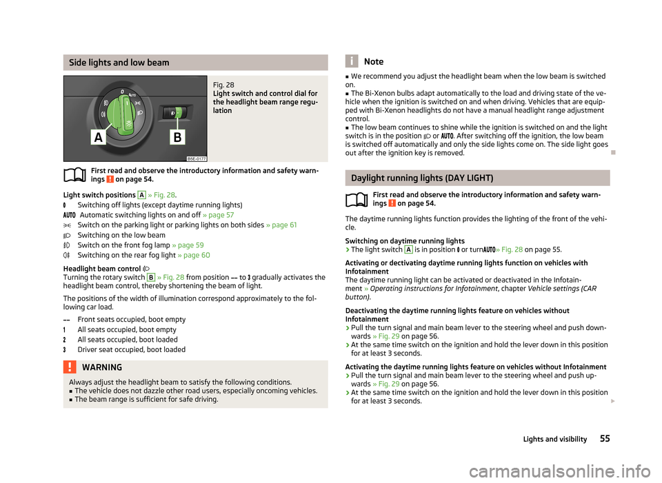
Light switch positions
A
» Fig. 28 .
Switching off lights (except daytime running lights) Automatic switching lights on and off » page 57
Switch on the parking light or parking lights on both sides » page 61
Switching on the low beam
Switch on the front fog lamp » page 59
Switching on the rear fog light » page 60
Headlight beam control
Turning the rotary switch
B
» Fig. 28 from position
to
gradually activates the
headlight beam control, thereby shortening the beam of light.
The positions of the width of illumination correspond approximately to the fol-
lowing car load.
Front seats occupied, boot empty
All seats occupied, boot empty
All seats occupied, boot loaded
Driver seat occupied, boot loaded
WARNINGAlways adjust the headlight beam to satisfy the following conditions.■The vehicle does not dazzle other road users, especially oncoming vehicles.■
The beam range is sufficient for safe driving.Note■ We recommend you adjust the headlight beam when the low beam is switched
on.■
The Bi-Xenon bulbs adapt automatically to the load and driving state of the ve-
hicle when the ignition is switched on and when driving. Vehicles that are equip- ped with Bi-Xenon headlights do not have a manual headlight range adjustment
control.
■
The low beam continues to shine while the ignition is switched on and the light
switch is in the position or . After switching off the ignition, the low beam
is switched off automatically and only the side lights come on. The side light goes
out after the ignition key is removed.
Daylight running lights (DAY LIGHT)
First read and observe the introductory information and safety warn-
ings
on page 54.
The daytime running lights function provides the lighting of the front of the vehi-
cle.
Switching on daytime running lights
›
The light switch
A
is in position
or turn
» Fig. 28 on page 55.
Activating or dectivating daytime running lights function on vehicles with Infotainment
The daytime running light can be activated or deactivated in the Infotain-
ment » Operating instructions for Infotainment , chapter Vehicle settings (CAR
button) .
Deactivating the daytime running lights feature on vehicles without
Infotainment
›
Pull the turn signal and main beam lever to the steering wheel and push down-
wards » Fig. 29 on page 56.
›
At the same time switch on the ignition and hold the lever down in this position
for at least 3 seconds.
Activating the daytime running lights feature on vehicles without Infotainment
›
Pull the turn signal and main beam lever to the steering wheel and push up- wards » Fig. 29 on page 56.
›
At the same time switch on the ignition and hold the lever down in this position
for at least 3 seconds.
55Lights and visibility
Page 62 of 287
Information message
The messages and information are indicated in the instrument cluster display. Fault: Light Assist
LIGHT ASSIST FAULT
Seek help from a specialist garage. Light Assist: clean the windscreen!
WINDSCREEN PLEASE CLEAN
Check for any obstacles on the windscreen in the viewing area of the camera.WARNINGHeadlight assist only functions as a support and does not relieve the driver of
his responsibility to check the headlights and light beam and, if necessary, to
switch on the lights depending on the light conditions. Manual operation may be required in the following situations.■
Poor visibility conditions, e.g. fog, heavy rain, thick snowfall.
■
The oncoming traffic is partially blocked on roads or motorways.
■
Passing poorly lit road users, e.g. cyclists.
■
Driving around “sharp” curves.
■
Driving on sharp slopes up/large inclines.
■
Driving through poorly-lit locations.
■
Driving over highly reflective surfaces.
■
The windscreen around the camera is dirty, iced up, misted up, or covered by
stickers.
■
Near the camera lens there is a light source, such as the screen of an exter-
nal navigation system.
CAUTION
Do not attach any stickers or similar objects to the windscreen to avoid impairing
the functions of the Assist system.Fog lightsFig. 32
Light switch
First read and observe the introductory information and safety warn-
ings on page 54.
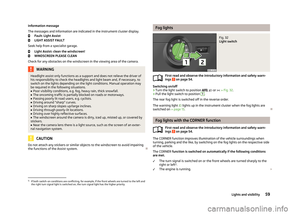
Switching on/off
›
Turn the light switch to position
,
or
» Fig. 32 .
›
Pull the light switch to position
1
.
The rear fog light is switched off in the reverse order.
The warning light
lights up in the instrument cluster when the fog lights are
switched on » page 15.
Fog lights with the CORNER function
First read and observe the introductory information and safety warn-ings
on page 54.
The CORNER function improves illumination of the vehicle surroundings when
turning, parking and the like, by switching on the fog lights on the respective side
of the vehicle.
The CORNER function is switched on automatically if the following conditions
are met.
The turn signal is switched on or the front wheels are turned sharply to the
right or left 1)
.
The engine is running.
1)
If both switch-on conditions are conflicting, for example, if the front wheels are turned to the left and
the right turn signal light is switched on, the turn signal light has the higher priority.
59Lights and visibility
Page 72 of 287
Interior mirrorFig. 43
Manual dimming mirror
Fig. 44
Automatic dimming mirror
First read and observe the introductory information and safety warn-
ings
on page 68.
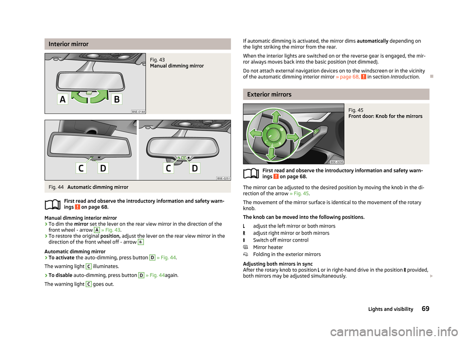
Manual dimming interior mirror
›
To dim the mirror set the lever on the rear view mirror in the direction of the
front wheel - arrow
A
» Fig. 43 .
›
To restore the original position, adjust the lever on the rear view mirror in the
direction of the front wheel off - arrow
B.
Automatic dimming mirror
›
To activate the auto-dimming, press button
D
» Fig. 44 .
The warning light
C
illuminates.
›
To disable auto-dimming, press button
D
» Fig. 44 again.
The warning light
C
goes out.
If automatic dimming is activated, the mirror dims automatically depending on
the light striking the mirror from the rear.
When the interior lights are switched on or the reverse gear is engaged, the mir- ror always moves back into the basic position (not dimmed).
Do not attach external navigation devices on to the windscreen or in the vicinity
of the automatic dimming interior mirror » page 68,
in section Introduction .
Exterior mirrors
Fig. 45
Front door: Knob for the mirrors
First read and observe the introductory information and safety warn-
ings on page 68.
The mirror can be adjusted to the desired position by moving the knob in the di-
rection of the arrow » Fig. 45.
The movement of the mirror surface is identical to the movement of the rotary knob.
The knob can be moved into the following positions.
adjust the left mirror or both mirrors
adjust right mirror or both mirrors
Switch off mirror control
Mirror heater
Folding in the exterior mirrors
Adjusting both mirrors in sync
After the rotary knob to position or in right-hand drive in the position
provided,
both mirrors may be adjusted simultaneously.
69Lights and visibility
Page 74 of 287
Seats and useful equipment
Adjusting the seats
Introduction
This chapter contains information on the following subjects:
Manually adjusting the front seats
72
Electric front seat adjustment
73
Head restraints
73
Memory function of the electrically adjustable seat
74
Memory function of the remote control key
75
The driver's seat should be adjusted in such a way that the pedals can be fully
pressed to the floor with slightly bent legs.
The seat backrest on the driver's seat should be adjusted in such a way that the
upper point of the steering wheel can be easily reached with slightly bent arms.
Correct adjustment of the seats is particularly important for the following: › Reaching the controls safely and quickly,
› A relaxed and fatigue-free body position.
› Achieving the maximum protection offered by the seat belts and the airbag
system.
WARNINGGeneral information■Caution when adjusting the seat! You may suffer injuries or bruises as a re-
sult of adjusting the seat without paying proper attention.■
The electric front seat adjustment is also functional when the ignition is
turned off (even with the ignition key removed). Therefore children should
never be left unattended in the vehicle.
■
The seat backrests must not be angled too far back when driving otherwise
this will affect proper operation of the seat belts and of the airbag system –
risk of injury!
■
Never carry more people than there are number of seats in the vehicle.
WARNING (Continued)■ Each occupant must correctly fasten the seat belt belonging to the seat.
Children must be fastened » page 193, Transporting children safely with a
suitable restraint system.■
At all times, the front seats and head restraints must be adjusted to match
the person's body size and the seat belt must be attached properly to provide
the most effective levels of protection to passengers.
■
Do not transport any objects on the front passenger seat except objects
(e.g. child safety seat) provided for this purpose – risk of accident!
WARNINGInformation for the driver■Only adjust the driver's seat when the vehicle is stationary – risk of accident!■
Maintain a distance of at least 25 cm from the steering wheel, and a dis-
tance of at least 10 cm between the legs and the dash panel at the height of
the knee airbag. Not maintaining this minimum distance will mean that the
airbag system will not be able to properly protect you – hazard!
■
Ensure that there are no objects in the driver's footwell, as these may get
caught in the pedal apparatus when driving or braking » page 126. You would
then no longer be able to operate the clutch, brake or accelerate.
WARNINGInformation for the front passenger■Maintain a distance of at least 25 cm to the dash panel. Not maintaining this
minimum distance will mean that the airbag system will not be able to proper-
ly protect you – hazard!■
Always keep your feet in the footwell when the car is being driven – never
place your feet on the dash panel, out of the window or on the surfaces of the
seats. You will be exposed to increased risk of injury when braking or in the
event of an accident. If an airbag is deployed, you may suffer fatal injuries
when adopting an incorrect seated position!
71Seats and useful equipment
Page 75 of 287
Note■After a certain time, play can develop within the adjustment mechanism of the
backrest angle.■
For safety reasons, it is not possible to store the seat position in the electric
seat memory and remote control key memory if the inclination angle of the seat
backrest is more than 102° in relation to the seat cushion.
■
Each time you store the position of the electrically adjustable driver's seat and
exterior mirrors, the existing setting is deleted.
Manually adjusting the front seats
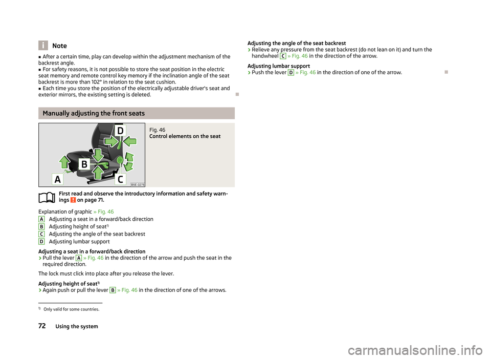
Fig. 46
Control elements on the seat
First read and observe the introductory information and safety warn-
ings on page 71.
Explanation of graphic » Fig. 46
Adjusting a seat in a forward/back direction Adjusting height of seat 1)
Adjusting the angle of the seat backrest
Adjusting lumbar support
Adjusting a seat in a forward/back direction
›
Pull the lever
A
» Fig. 46 in the direction of the arrow and push the seat in the
required direction.
The lock must click into place after you release the lever.
Adjusting height of seat 1)
›
Again push or pull the lever
B
» Fig. 46 in the direction of one of the arrows.
ABCDAdjusting the angle of the seat backrest›Relieve any pressure from the seat backrest (do not lean on it) and turn the
handwheel C
» Fig. 46 in the direction of the arrow.
Adjusting lumbar support
›
Push the lever
D
» Fig. 46 in the direction of one of the arrow.
1)
Only valid for some countries.
72Using the system