check engine SKODA OCTAVIA 2014 3.G / (5E) User Guide
[x] Cancel search | Manufacturer: SKODA, Model Year: 2014, Model line: OCTAVIA, Model: SKODA OCTAVIA 2014 3.G / (5E)Pages: 280, PDF Size: 35.53 MB
Page 46 of 280
Lamp failureRead and observe
on page 41 first.
The warning icon
comes on if a bulb is faulty.
The following message is shown in the information cluster display, for exam-
ple.
Check right dipped headlight beam!
DIPPED HEADLIGHT CHECK RIGHT
Diesel particulate filter (diesel engine)
Read and observe
on page 41 first.
The diesel particulate filter separates the soot particles from the exhaust. The
soot particles collect in the diesel particulate filter where they are burnt on a
regular basis.
If the warning icon
illuminates , soot has accumulated in the diesel particu-
late filter.
To clean the filter, and where traffic conditions permit »
, drive for at least
15 minutes or until the warning icon goes out as follows.
Gear 4 or gear 5 engaged (automatic gearbox: Position D/S).
Vehicle speed at least 70 km/h.
Engine speed between 1800-2500 rpm.
If the filter is properly cleaned, the warning icon
goes out .
If the filter is not properly cleaned, illumination of the warning icon
does
not take place and the warning light
begins to
flash.
The following message is shown in the information cluster display. Diesel particulate filter: Owner's manual!
DIESEL PM FILTER OWNER MANUAL
Seek assistance from a specialist garage immediately.
WARNING■ The diesel particulate filter reaches very high temperatures - there is a
fire hazard and serious injury could be caused. Therefore, never stop the
vehicle at places where the underside of your vehicle can come into contact
with flammable materials such as dry grass, undergrowth, leaves, spilled
fuel or such like.■
Always adjust your speed to suit weather, road, region and traffic condi-
tions. The recommendations indicated by the warning light must not tempt
you to disregard the national regulations for road traffic.
CAUTION
■ As long as the warning icon lights up, you must take into account an in-
creased fuel consumption and in certain circumstances a power reduction of
the engine.■
Using diesel fuel with an increased sulphur content can considerably reduce
the life of the diesel particle filter. A ŠKODA partner will be able to tell you
which countries use diesel fuel with a high sulphur content.
Note
■ We encourage you to avoid constant short journeys. This will improve the
combustion process of the soot particles in the diesel particulate filter.■
If the engine is turned off during the filter cleaning process or shortly after-
wards, the cooling fan may turn on automatically for a few minutes.
Windscreen washer fluid level
Read and observe
on page 41 first.
If the warning icon
comes on , the windscreen washer fluid level is too low.
The following message is shown in the information cluster display. Top up washer fluid!
WASHER FLUID PLEASE TOP UP
Top up with liquid » page 195, Windscreen washer system .
Fuel reserve
Read and observe
on page 41 first.
If the indicator symbol
comes on, the fuel level in the fuel tank has reached
the reserve area.
43Instruments and warning lights
Page 50 of 280
For instance, if appears in this display, this means it is recommended that
you shift from 3rd into 4th gear.
The gear recommendation is intended only for vehicles with a manual trans-
mission or for vehicles with an automatic transmission in manual shift mode
(Tiptronic).WARNINGThe driver is always responsible for selecting the correct gear in different
driving situations, such as overtaking.
For the sake of the environment
A suitably selected gear has the following advantages.■It helps to reduce fuel consumption.■
It reduces the operating noise.
■
It protects the environment.
■
It benefits the durability and reliability of the engine.
Door, luggage compartment or bonnet warning
Read and observe
on page 45 first.
If at least one door is open, or the boot or bonnet is open, the display indicates
the relevant open door or boot/bonnet.
An acoustic signal will also sound if you drive the vehicle above 6 km/h when a
door is opne.
Auto-check control
Read and observe
on page 45 first.
Certain functions and conditions of individual vehicle systems are checked
continuously when the ignition is switched on.
Error messages and other information appears on the display.
Some messages are displayed simultaneously with the warning
lights » page 34 or warning icons in the display » page 40.
While the operational faults remain unrectified, the messages are always indi- cated again. After the message is displayed for the first time, the symbols
or
continue to be displayed without any extra messages for the driver.
SymbolMeaningDangerWarning
Driving data (Multifunction display)
Introduction
This chapter contains information on the following subjects:
Memory
48
Information overview
48
Warning at excessive speeds
50
The driving data display is only possible with the ignition switched on.
After the ignition is switched on, the function that was last selected before
switching off the ignition is displayed.
Individual information can be shown or hidden in the infotainment sys-
tem » Infotainment operating instructions , chapter Vehicle settings (CAR but-
ton) .
WARNINGConcentrate fully at all times on your driving! As the driver, you are fully re-
sponsible for the operation of your vehicle.
Note
In some national versions the displays appear in the Imperial system of meas-
urement.47Information system
Page 52 of 280
Average fuel consumption
The average fuel consumption 1)
is calculated since the last time the memory
was erased.
If you wish to determine the average fuel consumption over a certain period of
time, you must set the memory at the start of the new measurement to
zero » page 48 .
After erasing the memory, no fuel consumption data will appear for the first
100 m driven.
The indicated information is updated continuously while you are driving.
With G-TEC vehicles, the average consumption of fuel currently being used is displayed.
Current fuel consumption
You can use this information to adapt your driving style to the desired fuel
consumption 1 )
.
The display appears in litres/hour 2)
or in kg/h 3)
if the vehicle is stationary or be-
ing driven at a low speed.
With G-TEC vehicles, the current consumption of fuel currently being used is
displayed.
Oil temperature
If the engine oil temperature is in the range 80-110 °C, the engine operating
temperature is reached.
If the oil temperature is lower than 80 °C or above 110 °C, avoid high engine
revs, full throttle and high engine loads.
If the oil temperature is lower than 50 °C or if a fault in the system for check-
ing the oil temperature is present, are displayed instead of the oil tempera-
ture.
Warning against excessive speeds
Set the speed limit, for example, for the maximum permissible speed in
town » page 50 .Traffic sign recognition
The display can show up to three of the following traffic signs simultaneously.
› Speed limits (including additional signs).
› Overtaking prohibited.
Further information » page 164, Traffic sign recognition .
Current driving speed
The current speed displayed is identical to the display on the speedometer3
» Fig. 22 on page 31 .
Average speed
The average speed since the memory was last erased is displayed in km/hour .
To determine the average speed over a certain period of time, set the memory
to zero at the start of the measurement » page 48.
After erasing the memory, no data will appear for the first 300 m driven.
The indicated information is updated continuously while you are driving.
Distance travelled
The distance travelled since the memory was last erased is displayed.
If you want to measure the distance travelled from a particular moment in time
on, at this moment, reset the memory by setting the button to zero » page 48.
The maximum distance indicated is 9999 km. The indicator is automatically set
back to zero if this period is exceeded.
Driving time
The time travelled since the memory was last erased is displayed.
If you want to measure the time travelled from a particular moment in time on,
at this moment, reset the memory by setting the button to zero » page 48.
The maximum distance indicated is 99 hours and 59 minutes. The indicator is
automatically set back to zero if this period is exceeded.
Convenience consumers
There, the total consumption of all consumer comfort in l / h is displayed.
1)
The units for the displayed consumption are set in the Infotainment
» Infotainment operating instruc-
tions , chapter Device settings .
2)
On some models in certain countries, the display appears in --,- kilometres/litres if the vehicle is station-
ary.
3)
In natural gas mode.
49Information system
Page 57 of 280
Unlocking and opening
Unlocking and locking
Introduction
This chapter contains information on the following subjects:
Locking/unlocking using the key via the lock cylinder
55
Unlocking/locking with the remote control key
55
Opening/closing a door
56
Unlocking / locking - KESSY
56
Safe securing system
57
Individual settings
57
Locking and unlocking the vehicle with the central locking button
58
Child safety lock
58
Malfunctions
58
Your car is equipped with a central locking system.
The central locking system allows you to lock and unlock all doors, the fuel fill-
er flap and the boot lid at the same time.
Depending on the equipment configuration, the following applies after
unlocking
› The turn signal lights flash twice as confirmation that the vehicle has been
unlocked.
› The doors, the boot lid and the fuel filler flap are unlocked.
› The interior light operated via the door contact illuminates.
› The SafeLock system is switched off.
› The indicator light in the driver door stops flashing.
› The exterior mirrors are folded back into the driving position.
› The anti-theft alarm system is deactivated.
If the vehicle is unlocked and a door or the boot lid not opened within the next
45 seconds, the vehicle will lock again automatically and the safe securing sys-
tem or anti-theft alarm system will be switched back on. This function is inten-
ded to prevent the car being unlocked unintentionally.
The seat and mirror are adjusted after the vehicle is unlocked » page 89.
Depending on the equipment configuration, the following applies after
locking
› The turn signal lights flash once as confirmation that the vehicle has been
locked.
› The doors, the boot lid and the fuel filler flap are locked.
› The interior light operated via the door contact goes out.
› The SafeLock system is switched on.
› The warning light in the driver door begins flashing.
› The exterior mirrors are folded back into the park position.
› The anti-theft alarm system is activated.
If the doors or the luggage compartment lid remain open after the vehicle has
been locked, the turn signal lights do not flash until they have been closed.
The current position of the seat and mirror after the vehicle is
locked » page 89 .WARNING■
Never leave the key in the vehicle when you exit the vehicle. Unauthor-
ized persons, such as children, for example, could lock the car, turn on the
ignition or start the engine - there is a danger of injury and accidents!■
When leaving the vehicle, never leave persons who are not completely in-
dependent, such as children, unattended in the vehicle. The children might,
for example, release the handbrake or take the vehicle out of gear. The ve-
hicle could then start to move – risk of injury and accidents! These individu-
als might also not be able to leave the vehicle on their own or to help
themselves. Can be fatal at very high or very low temperatures!
CAUTION
■ Each key contains electronic components; therefore it must be protected
against moisture and severe shocks.■
Keep the groove of the keys absolutely clean. Impurities (textile fibres, dust,
etc.) have a negative effect on the functionality of the locking cylinder and ig-
nition lock.
■
The battery must be replaced if the central locking or anti-theft alarm system
does react to the remote control at less than approx. 3 metres
away » page 224 .
■
When leaving the vehicle, always check if it is locked.
■
If the driver's door has been opened, the vehicle cannot be locked.
54Using the system
Page 124 of 280
■As soon as the windscreen mists up, press the symbol button . Press the
button once the windscreen has demisted.■
During operation of the Climatronic, an increase in engine idle speed can oc-
cur under certain circumstances in order to ensure adequate heating comfort.
Efficient handling of the cooling system
Read and observe
and on page 116 first.
The air conditioning system compressor uses power from the engine when in
cooling mode, which will affect the fuel consumption.
It recommended to open the windows or the doors of a vehicle for which the
interior has been strongly heated through the effect of direct sunlight in order
to allow the heated air to escape.
The cooling system should not be on if the windows are open.
For the sake of the environment
Pollutant emissions are also lower when fuel is being saved » page 136.
malfunctions
Read and observe
and on page 116 first.
If the cooling system does not operate at outside temperatures higher than
+5 °C, there is a problem in the system. The reasons for this may be.
› One of the fuses has blown. Check the fuse and replace if necessa-
ry » page 229 .
› The cooling system has switched off automatically for a short time because
the coolant temperature of the engine is too hot » page 32.
If you are not able to resolve the operational problem yourself, or if the cooler
output has reduced, switch off the cooling system and seek assistance from a
specialist garage.
Auxiliary heating (auxiliary heating and ventilation)
Introduction
This chapter contains information on the following subjects:
Switching on/off
122
Radio remote control
123Conditions for the functioning of auxiliary heating (auxiliary heating and venti-
lation), hereinafter referred to only as auxiliary heating.
The charge state of the vehicle battery is sufficient.
The fuel supply is adequate (the warning icon
is not lit in the display of
the instrument cluster).
Auxiliary ventilation
The auxiliary ventilation enables fresh air to flow into the vehicle interior by
switching off the engine, whereby the interior temperature is effectively de-
creased (e.g. with the vehicle parked in the sun).
Auxiliary heating (parking heating)
The auxiliary heating can be used when both when stationary, when the en-
gine is switched off, to preheat the vehicle and also while driving (e.g. during
the heating phase of the engine).
The auxiliary heater functions in connection with the air-conditioning system
or Climatronic.
The auxiliary heating also warms up the engine.
The auxiliary heating warms up the coolant by combusting fuel from the vehi-
cle tank. This heats the air flowing into the passenger compartment (if the
blower is turned on).
The heater is switched on or off automatically depending on the ambient con-
ditions to give the best possible conditions for the engine running and the in-
terior heating.
The automatic switching on and off of the heater can be turned off by a spe-
cialist garage.WARNING■ The auxiliary heating must never be operated in closed rooms (e.g. garag-
es) – risk of poisoning!■
The auxiliary heating must not be allowed to run during refuelling – risk
of fire.
■
The exhaust pipe of the auxiliary heating is located on the underside of
the vehicle. If you want to use the heater, do not park the car in places
where the exhaust fumes can come into contact with flammable materials
such as dry grass, undergrowth, leaves, spilled fuel etc. - risk of fire.
121Heating and air conditioning
Page 127 of 280

Communication
SmartGate
Introduction
This chapter contains information on the following subjects:
Connection with SmartGate
124
Smart Gate website
125
Password management
125
SmartGate is a system which transmits vehicle data via Wi-Fi.
The ŠKODA applications installed in a connected communications device (e.g.
phone, tablet, notebook) 1)
offer the possibility to further process the received
data.
Available applications and further information can be found on the ŠKODA
website.
WARNING■ The national legal regulations for using mobile communication devices in
a vehicle must be observed.■
Do not fit the equipment or fixtures onto airbag covers or within the im-
mediate deployment range of the airbags.
■
Never leave a connected device in the deployment area of an airbag, on a
seat, on the dash panel or any another area from where it can be thrown
during a sudden braking manoeuvre, an accident or a collision - risk of in-
jury.
Note
The Wi-Fi range is limited to the interior of the vehicle.
Connection with SmartGate
Read and observe
on page 124 first.
For a successful connection the following conditions must be met.
Wi-Fi is turned on in the device to be connected.
The ignition is switched on.
Connect›
Enable the connected device to search for available Wi-Fi networks (see op-
erating instructions for the connected device).
›
In the Found networks menu, select the connection to the
“SmartGate_ ... ”network 2)
.
›
Enter the password (the password is pre-set as the complete Vehicle Identi-
fication Number at the factory - enter in capital letters).
Disconnect the connection
The connection to SmartGate can be terminated in the following ways.
›
By disconnecting the connected device from SmartGate.
›
By turning off the Wi-Fi in the connected device.
›
By switching off the ignition and removing the key for more than 5 secs (for
vehicles with starter button, by turning off the engine and opening the driv-
er's door).
Automatic connection
The connection to SmartGate is automatically restored under the following
conditions.
Wi-Fi is turned on in the device to be connected.
The ignition is switched on.
The device to be connected has saved the password required for the con-
nection check.
Connection problems
If the connection fails, check the following points.
› Are the conditions for successful connection fulfilled?
› Is Smart Gate available in the list of available Wi-Fi networks?
› Has the password required for the connection check been entered?
› Is the password required for the connection check correct?
› Is the device to be connected still connected to another Wi-Fi network?
If the above items are ok but the connection still fails, contact a ŠKODA Part-
ner.
1)
The applications support communication devices with the Android operating system version 4.0.x and
higher, as well as iOS 7.xx and higher.
2)
The last six symbols of the VIN vehicle identification number of your vehicle are displayed at position ....
124Using the system
Page 134 of 280
The brake pads wear more quickly if a lot of journeys are completed in towns
and over short distances or if a very sporty style of driving is adopted.
If operated under severe conditions , the thickness of the brake pads must be
checked by a specialist garage between service appointments as well.
Wet roads or road salt
The performance of the brakes can be delayed as the brake discs and brake
pads may be moist or have a coating of ice or layer of salt on them in winter.
The brakes are cleaned and dried by applying the brakes several times »
.
Corrosion
Corrosion on the brake discs and dirt on the bake pads occur if the vehicle has
been parked for a long period and if you do not make much use of the braking
system. The brakes are cleaned and dried by applying the brakes several
times »
.
Long or steep slopes
Before travelling a long distance with a steep gradient, reduce speed and shift
into the next lowest gear. As a result, the braking effect of the engine will be
used, reducing the load on the brakes. Any additional braking should be com-
pleted intermittently, not continuously.
Emergency brake display
If the brakes are applied in full and the control unit for the braking system con-
siders the situation to be dangerous for the following traffic, the brake light
flashes automatically.
After the speed was reduced below around 10 km/h or the vehicle was stop-
ped, the brake light stops flashing and the hazard warning light system
switches on. The hazard warning light system is switched off automatically af- ter accelerating or driving off again.
Faults in the brake surface
If it is found that the braking distance has suddenly become longer and that
the brake pedal can be depressed further, the brake system may be faulty.
Visit a specialist garage immediately and adjust your style of driving appropri-
ately, as you will not know the exact extent of the damage.
Low brake fluid level
An insufficient level of brake fluid may result in problems in the brake system.
The level of the brake fluid is monitored electronically » page 35,
Brake sys-
tem .
Brake booster
The brake booster increases the pressure generated with the brake pedal. The
brake booster only operates when the engine is running.WARNINGOnly apply the brakes for the purpose of drying and cleaning the brake
discs if the traffic conditions permit this. Do not place any other road users
in jeopardy.
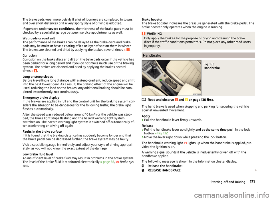
Handbrake
Fig. 132
Handbrake
Read and observe and on page 130 first.
The hand brake is used when stopping and parking for securing the vehicle
against unwanted movement.
Apply
›
Pull the handbrake lever firmly upwards.
Release
›
Pull the handbrake lever up slightly and at the same time push in the lock
button » Fig. 132 .
›
Move the lever right down while pressing the lock button.
The handbrake warning light
lights up when the handbrake is applied, pro-
vided the ignition is on.
A warning signal sounds if the vehicle is inadvertently driven off with the
handbrake applied.
The following message is shown in the information cluster display. Release the handbrake!
RELEASE HANDBRAKE
131Starting-off and Driving
Page 140 of 280
Driving through water and driving off of made-up roads
Introduction
This chapter contains information on the following subjects:
Driving through water
137
Driving off paved roads
137WARNINGImmediately after driving through water, mud, slush and the like, braking
effectiveness will be temporarily impaired » page 130, Information on brak-
ing . For this reason, sudden and violent braking manoeuvres are to be
avoided - there is a risk of accident!
Driving through water
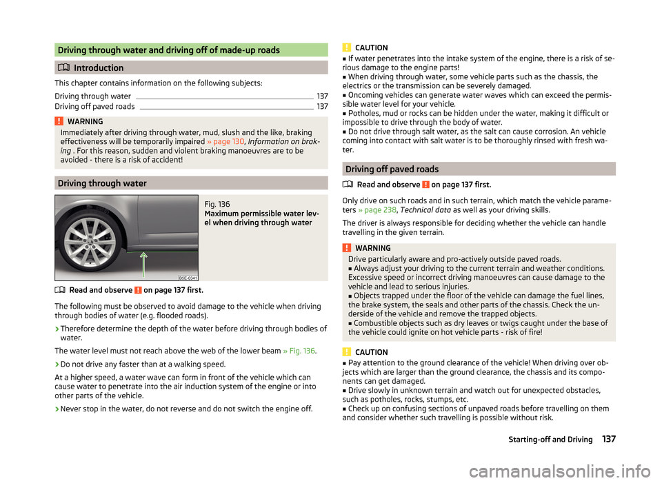
Fig. 136
Maximum permissible water lev-
el when driving through water
Read and observe on page 137 first.
The following must be observed to avoid damage to the vehicle when driving through bodies of water (e.g. flooded roads).
›
Therefore determine the depth of the water before driving through bodies of
water.
The water level must not reach above the web of the lower beam » Fig. 136.
›
Do not drive any faster than at a walking speed.
At a higher speed, a water wave can form in front of the vehicle which can
cause water to penetrate into the air induction system of the engine or into
other parts of the vehicle.
›
Never stop in the water, do not reverse and do not switch the engine off.
CAUTION■ If water penetrates into the intake system of the engine, there is a risk of se-
rious damage to the engine parts!■
When driving through water, some vehicle parts such as the chassis, the
electrics or the transmission can be severely damaged.
■
Oncoming vehicles can generate water waves which can exceed the permis-
sible water level for your vehicle.
■
Potholes, mud or rocks can be hidden under the water, making it difficult or
impossible to drive through the body of water.
■
Do not drive through salt water, as the salt can cause corrosion. An vehicle
coming into contact with salt water is to be thoroughly rinsed with fresh wa-
ter.
Driving off paved roads
Read and observe
on page 137 first.
Only drive on such roads and in such terrain, which match the vehicle parame-ters » page 238 , Technical data as well as your driving skills.
The driver is always responsible for deciding whether the vehicle can handle
travelling in the given terrain.
WARNINGDrive particularly aware and pro-actively outside paved roads.■Always adjust your driving to the current terrain and weather conditions.
Excessive speed or incorrect driving manoeuvres can cause damage to the
vehicle and lead to serious injuries.■
Objects trapped under the floor of the vehicle can damage the fuel lines,
the brake system, the seals and other parts of the chassis. Check the un-
derside of the vehicle and remove the trapped objects.
■
Combustible objects such as dry leaves or twigs caught under the base of
the vehicle could ignite on hot vehicle parts - risk of fire!
CAUTION
■ Pay attention to the ground clearance of the vehicle! When driving over ob-
jects which are larger than the ground clearance, the chassis and its compo-
nents can get damaged.■
Drive slowly in unknown terrain and watch out for unexpected obstacles,
such as potholes, rocks, stumps, etc.
■
Check up on confusing sections of unpaved roads before travelling on them
and consider whether such travelling is possible without risk.
137Starting-off and Driving
Page 153 of 280
WARNING■The system only serves to support and does not relieve the driver of the
responsibility for the vehicle operation.■
The driver must always be ready to take over steering of the vehicle him-
self (accelerate or brake).
■
Always adapt your speed and safety proximity to the vehicle ahead to the
current visibility, weather, road and traffic conditions.
WARNING■ The ACC does not react when approaching a stationary obstacle, such as
traffic jams, vehicle breakdowns or vehicles waiting at a traffic light.■
The ACC does not respond to crossing or oncoming objects.
■
If the ACC does not decelerate fast enough, immediately apply the vehi-
cle's foot brake.
WARNINGFor safety reasons, do not use the ACC under the following conditions.■When driving in turning lanes, motorway exits or construction sites, to
avoid an unwanted acceleration to the stored speed.■
When visibility is poor, (e.g. fog, heavy rain, thick snowfall).
■
When road conditions are poor (e.g. ice, slippery road, gravel, dirt road).
■
When driving around “sharp” bends.
■
When riding on a steep gradient / high slope.
CAUTION
The control may automatically switch off when some brake assist systems (e.g.
ESC) intervene, when the maximum permissible engine speed is exceeded, etc.
Note
■ The ACC is designed primarily for use on motorways.■The ACC reduces the speed by automatically releasing the accelerator or by
means of a braking procedure as appropriate. If the brakes are used for an au-
tomatic speed reduction at any moments, then the brake light illuminates.■
In case of failure of more than one brake light on the vehicle or on the elec-
trically connected trailer, the ACC becomes unavailable.
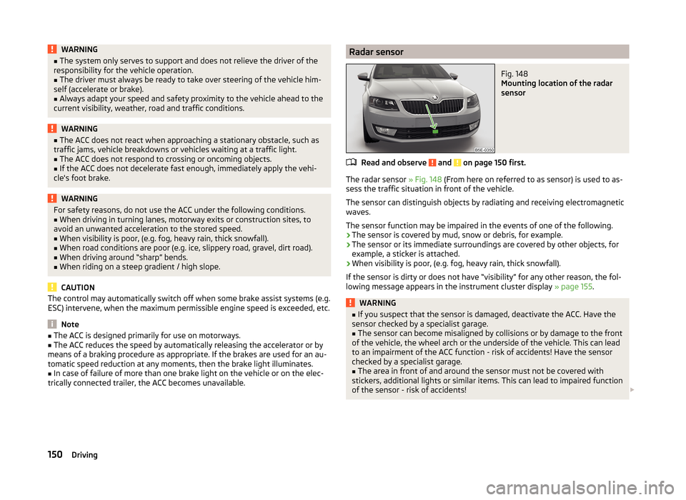
Radar sensorFig. 148
Mounting location of the radar
sensor
Read and observe and on page 150 first.
The radar sensor » Fig. 148 (From here on referred to as sensor) is used to as-
sess the traffic situation in front of the vehicle.
The sensor can distinguish objects by radiating and receiving electromagnetic waves.
The sensor function may be impaired in the events of one of the following.
› The sensor is covered by mud, snow or debris, for example.
› The sensor or its immediate surroundings are covered by other objects, for
example, a sticker is attached.
› When visibility is poor, (e.g. fog, heavy rain, thick snowfall).
If the sensor is dirty or does not have “visibility” for any other reason, the fol- lowing message appears in the instrument cluster display » page 155.
WARNING■
If you suspect that the sensor is damaged, deactivate the ACC. Have the
sensor checked by a specialist garage.■
The sensor can become misaligned by collisions or by damage to the front
of the vehicle, the wheel arch or the underside of the vehicle. This can lead
to an impairment of the ACC function - risk of accidents! Have the sensor
checked by a specialist garage.
■
The area in front of and around the sensor must not be covered with
stickers, additional lights or similar items. This can lead to impaired function
of the sensor - risk of accidents!
150Driving
Page 161 of 280
START-STOP
Introduction
This chapter contains information on the following subjects:
Operating conditions of the system
158
Operation in vehicles with manual gearbox
158
Operation in vehicles with automatic gearbox
159
System related automatic start-up
159
Manually deactivating/activating the system
159
Information messages
160
The START-STOP system (hereinafter referred to as the system) saves fuel and
reduces polluting emissions and CO 2 emissions by turning the engine off, e.g.
when stopping at traffic lights, and starting the engine again when moving off.
WARNING■ Never let the vehicle roll with the engine switched off.■The brake servo unit and power steering only operate if the engine is run-
ning.
Operating conditions of the system
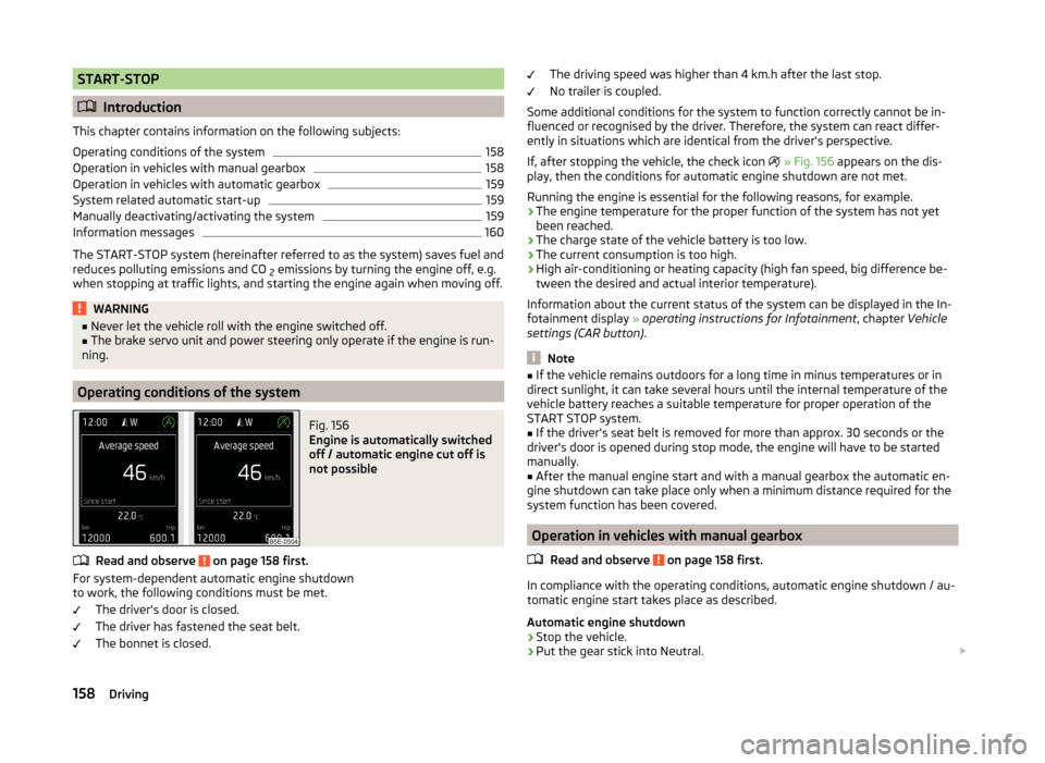
Fig. 156
Engine is automatically switched
off / automatic engine cut off is
not possible
Read and observe on page 158 first.
For system-dependent automatic engine shutdown
to work, the following conditions must be met.
The driver's door is closed.
The driver has fastened the seat belt.
The bonnet is closed.
The driving speed was higher than 4 km.h after the last stop.
No trailer is coupled.
Some additional conditions for the system to function correctly cannot be in-
fluenced or recognised by the driver. Therefore, the system can react differ-
ently in situations which are identical from the driver's perspective.
If, after stopping the vehicle, the check icon
» Fig. 156 appears on the dis-
play, then the conditions for automatic engine shutdown are not met.
Running the engine is essential for the following reasons, for example.
› The engine temperature for the proper function of the system has not yet
been reached.
› The charge state of the vehicle battery is too low.
› The current consumption is too high.
› High air-conditioning or heating capacity (high fan speed, big difference be-
tween the desired and actual interior temperature).
Information about the current status of the system can be displayed in the In-
fotainment display » operating instructions for Infotainment , chapter Vehicle
settings (CAR button) .
Note
■
If the vehicle remains outdoors for a long time in minus temperatures or in
direct sunlight, it can take several hours until the internal temperature of the
vehicle battery reaches a suitable temperature for proper operation of the
START STOP system.■
If the driver's seat belt is removed for more than approx. 30 seconds or the
driver's door is opened during stop mode, the engine will have to be started
manually.
■
After the manual engine start and with a manual gearbox the automatic en-
gine shutdown can take place only when a minimum distance required for the
system function has been covered.
Operation in vehicles with manual gearbox
Read and observe
on page 158 first.
In compliance with the operating conditions, automatic engine shutdown / au-
tomatic engine start takes place as described.
Automatic engine shutdown
›
Stop the vehicle.
›
Put the gear stick into Neutral.
158Driving