headlights SKODA OCTAVIA 2014 3.G / (5E) User Guide
[x] Cancel search | Manufacturer: SKODA, Model Year: 2014, Model line: OCTAVIA, Model: SKODA OCTAVIA 2014 3.G / (5E)Pages: 280, PDF Size: 35.53 MB
Page 178 of 280
Detaching›Unhook the breakaway cable of the trailer from the security eyeletB
» Fig. 178.
›
Pull the trailer cable connected out of the 13-pin socket.
›
Remove the trailer from the ball head.
›
Place cap
5
on to the ball head » Fig. 166 on page 169 .
›
Grip the 13-pin socket at point
A
and swivel in the opposite direction to the
arrow » Fig. 178 .
Exterior mirrors
You have to have additional exterior mirrors fitted if you are not able to see
the traffic behind the trailer with the standard rear-view mirrors. The national
legal requirements must be observed.
Headlights
The front of the vehicle may lift up when a trailer is being towed and the head-
lights may dazzle other road users.
Adjust the headlights using the headlight beam control » page 71, Operating
the lights 1)
.
Power to the trailer power grid
For the electrical connection between the vehicle and trailer, the trailer's pow-
er supply is provided by the vehicle.
The power supply works with ignition on or off.
WARNING■ Incorrectly or improperly connected electrical installations may cause the
entire vehicle electronics to malfunction, and may lead to accidents and se-
rious injury from electric shock.■
Work on the electrical system must only be carried out by specialist ga-
rages.
■
Never directly connect the trailer's electrical system with the electrical
connections for the tail lights or other current sources.
■
After attaching the trailer and connecting the power socket, check that
the rear lights on the trailer are working correctly.
■
The handbrake on the vehicle must be applied when attaching and dis-
connecting the trailer.
■
Never use the safety eye to tow a vehicle!
Loading a trailer
The vehicle/trailer combination must be balanced. whereby the maximum per-
missible drawbar load must be utilised. If the drawbar load is too low, it jeop-
ardises the performance of the vehicle/trailer combination.
Distribution of the load
Distribute the load in the trailer in such a way that heavy items are located as
close to the trailer axle as possible. Secure the items from slipping.
The distribution of the weight is very poor if your vehicle is unladen and the
trailer is laden. Drive at a particularly low speed if you cannot avoid driving
with this combination.
Tyre pressure
Correct the tyre inflation pressure on the vehicle for a “full load” » page 204.
Towing capacity and trailer weight
The permissible trailer load must not be exceeded under any circumstan-
ces » page 238 , Technical data .
The details given in the vehicle's technical documentation always take prece-
dence over the details in the Owner's Manual.
The trailer loads specified apply only to altitudes up to 1 000 metres above
mean sea level.
The engine output falls as the height increases, as does the ability to climb.
Therefore, for every additional 1000 m in height (or part), the maximum per-
missible towed weight must be reduced by 10%.
The towed weight is made up of the actual weights of the loaded towing vehi-
cle and the loaded trailer.
The trailer and drawbar load information on the type plate of the towing de-
vice are merely test data for the towing device. The vehicle-specific values are
detailed in the vehicle documents.WARNING■ The maximum permissible axle and drawbar load and the permissible
weight of the trailer must not be exceeded - risk of accident!■
Sliding cargo can significantly adversely affect stability and driving safety
- risk of accident!
1)
Applies to vehicles with bi-xenon headlights.
175Hitch and trailer
Page 187 of 280
■Do not remove snow or ice from glass parts using warm or hot water – risk of
cracks forming in the glass.■
Make sure that when removing snow and ice from the windows, the labels
attached to the vehicle by the factory are not damaged.
CAUTION
Information for cleaning windows■Do not clean the inside of the windows with sharp-edged objects or corro-
sive and acidic cleaning agents – there is a risk of damaging the heating ele-
ments or window aerial.■
When drying the windows after washing the vehicle, do not use window
leathers that have been used to polish the bodywork. Residues of preserva-
tives in the window leather can dirty the window and reduce visibility.
Headlight glasses
Read and observe
and on page 182 first.
Clean plastic front headlight lenses using clean, warm water and soap.
CAUTION
■The headlights are never to be wiped dry - there is a risk of damaging the
protective lacquer and the headlight glass subsequently developing cracks.■
Do not use sharp objects to clean the glasses - there is a risk of damaging
the protective lacquer and the headlight glasses subsequently developing
cracks.
■
Do not use any aggressive cleaning or chemical solvent products to clean the
headlights – risk of damaging the headlight lenses.
Camera lens
Read and observe
and on page 182 first.
Moisten the lens of the rear view camera first with clean water and then dry
with a dry cloth.
Remove the snow from the lens with a brush and the ice from the lens with
de-icing agents specifically developed for these purposes.
CAUTION■ Remove snow or ice on the lens with warm or hot water - there is a risk of
damaging the lens.■
Never use cleaners containing abrasive effect to clean the lens.
■
Never use pressurized water or steam jet to clean the lens.
Door closing cylinder
Read and observe
and on page 182 first.
Specific products must be used for de-icing door lock cylinders.
CAUTION
Make sure that as little water as possible gets into the locking cylinder when
washing the vehicle - there is a risk of freezing the lock cylinder!
Cavity protection
Read and observe
and on page 182 first.
All the cavities of your vehicle which are at risk from corrosion are protected
for life by a layer of protective wax applied in the factory.
Wax protection does not require to be inspected or re-treated.
If any small amount of wax flow out of the cavities at high temperatures, these
must be removed with a plastic scraper and the stains cleaned using a petrole-
um cleaner.
WARNINGSafety regulations should be observed when using petroleum cleaner to re-
move wax – risk of fire!
Jack
Read and observe
and on page 182 first.
The jack is maintenance-free.
If necessary, the moving parts of the jack should be lubricated with a suitable
lubricant.
184General Maintenance
Page 198 of 280
NoteThe location of the inspection points in the engine compartment of petrol and
diesel engines is practically identical.
Radiator fan
Read and observe
and on page 193 first.
The radiator fan is powered by an electric motor. Operation is controlled ac-
cording to the temperature of the coolant.
WARNINGAfter switching off the ignition, the fan can intermittently continue to oper-
ate for approx. 10 minutes.
Windscreen washer system
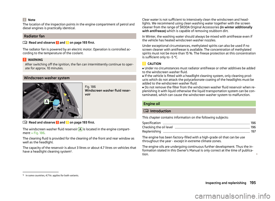
Fig. 186
Windscreen washer fluid reser-
voir
Read and observe and on page 193 first.
The windscreen washer fluid reservoir
A
is located in the engine compart-
ment » Fig. 186 .
The cleaning fluid is provided for the cleaning of the front and rear window as
well as the headlight.
The capacity of the reservoir is about 3 litres or about 4.7 litres on vehicles that
have a headlight cleaning system 1)
.
Clear water is not sufficient to intensively clean the windscreen and head-
lights. We recommend using clean washing water together with the screen
cleaner from the range of ŠKODA Original Accessories (in winter additionally
with antifreeze) which is capable of removing stubborn dirt.
In Winter, the washing water should always be mixed with antifreeze even if
the vehicle has heated windscreen washer nozzles.
Under exceptional circumstances, methylated spirits can also be used if no
screen cleaner with antifreeze is available. The concentration of methylated
spirits must not be more than 15 %. The freeze protection at this concentration
is sufficient only to -5 °C.
CAUTION
■ Under no circumstances must radiator antifreeze or other additives be added
to the windscreen washer fluid.■
If the vehicle is fitted with a headlight cleaning system, only cleaning prod-
ucts which do not attack the polycarbonate coating of the headlights must be
added to the windscreen washer fluid.
■
Do not remove the filter from the windscreen washer fluid reservoir when re-
plenishing it with liquid otherwise the liquid transportation system can be con-
taminated, which can cause the windscreen washer system to malfunction.
Engine oil
Introduction
This chapter contains information on the following subjects:
Specification
196
Checking the oil level
196
Replenishing
197
The engine has been factory-filled with a high-grade oil that can be use
throughout the year - except in extreme climate zones.
The engine oils are undergoing continuous further development. Thus the in- formation stated in this Owner's Manual is only correct at the time of publica-
tion.
1)
In some countries, 4.7 ltr. applies for both variants.
195Inspecting and replenishing
Page 201 of 280
WARNING (Continued)■If coolant is swallowed, consult a doctor immediately.■Never spill operating fluids over the hot engine - risk of fire.
CAUTION
■If for some reason it is not possible to top up the coolant under the current
circumstances, do not continue driving! Switch off the engine and seek as-
sistance from a specialist garage.■
If the expansion tank is empty, do not top up with coolant. The system could
aerate - risk of engine damage,
do not continue driving! Switch off the en-
gine and seek assistance from a specialist garage.
■
The amount of coolant additive in the coolant must never be allowed to be
less than 40 %.
■
Over 60 % of coolant additive in the coolant reduces the antifreeze protec-
tion and coolant effectiveness.
■
A coolant additive that does not comply with the correct specification can
significantly reduce the corrosion protection of the cooling system.
■
Any faults resulting from corrosion may cause a loss of coolant and can con-
sequently result in major engine damage!
■
Do not fill the coolant above the mark
A
» Fig. 188 on page 198 .
■
If an error occurs, leading to the engine overheating, the help of a professio-
nal garage is to be sought - there is a risk of serious engine damage occurring.
■
Additional headlights and other attached components in front of the air inlet
impair the cooling efficiency of the coolant.
■
Never cover the radiator - there is a risk of the engine overheating.
Note
On vehicles that are fitted with an auxiliary heater (auxiliary heating and venti-
lation), the coolant capacity is approx. 1 l larger.
Checking the coolant level
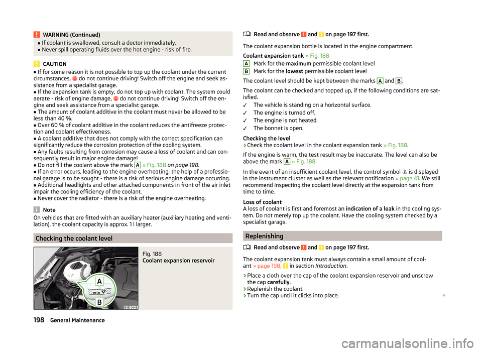
Fig. 188
Coolant expansion reservoir
Read and observe and on page 197 first.
The coolant expansion bottle is located in the engine compartment.
Coolant expansion tank » Fig. 188
Mark for the maximum permissible coolant level
Mark for the lowest permissible coolant level
The coolant level should be kept between the marks
A
and
B
.
The coolant can be checked and topped up, if the following conditions are sat-
isfied.
The vehicle is standing on a horizontal surface.
The engine is turned off.
The engine is not heated.
The bonnet is open.
Checking the level
›
Check the coolant level in the coolant expansion tank » Fig. 188.
If the engine is warm, the test result may be inaccurate. The level can also be
above the mark
A
» Fig. 188 .
In the event of an insufficient coolant level, the control symbol is displayed
in the instrument cluster as well as the relevant notification » page 41. We still
recommend inspecting the coolant level directly at the expansion tank from
time to time.
Loss of coolant
A loss of coolant is first and foremost an indication of a leak in the cooling sys-
tem. Do not merely top up the coolant. Have the cooling system checked by a
specialist garage.
Replenishing
Read and observe
and on page 197 first.
The coolant expansion tank must always contain a small amount of cool-
ant » page 198, in section Introduction .
›
Place a cloth over the cap of the coolant expansion reservoir and unscrew
the cap carefully .
›
Replenish the coolant.
›
Turn the cap until it clicks into place.
AB198General Maintenance
Page 234 of 280
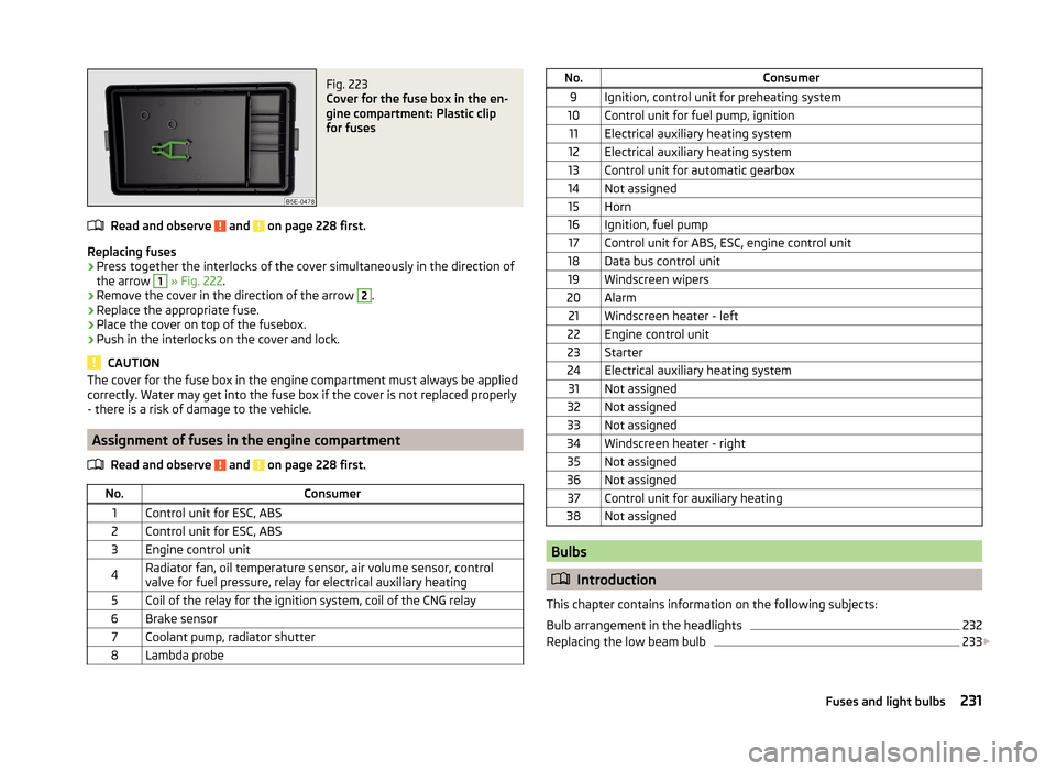
Fig. 223
Cover for the fuse box in the en-
gine compartment: Plastic clip
for fuses
Read and observe and on page 228 first.
Replacing fuses
›
Press together the interlocks of the cover simultaneously in the direction of
the arrow
1
» Fig. 222 .
›
Remove the cover in the direction of the arrow
2
.
›
Replace the appropriate fuse.
›
Place the cover on top of the fusebox.
›
Push in the interlocks on the cover and lock.
CAUTION
The cover for the fuse box in the engine compartment must always be applied
correctly. Water may get into the fuse box if the cover is not replaced properly
- there is a risk of damage to the vehicle.
Assignment of fuses in the engine compartment
Read and observe
and on page 228 first.
No.Consumer1Control unit for ESC, ABS2Control unit for ESC, ABS3Engine control unit4Radiator fan, oil temperature sensor, air volume sensor, control
valve for fuel pressure, relay for electrical auxiliary heating5Coil of the relay for the ignition system, coil of the CNG relay6Brake sensor7Coolant pump, radiator shutter8Lambda probeNo.Consumer9Ignition, control unit for preheating system10Control unit for fuel pump, ignition11Electrical auxiliary heating system12Electrical auxiliary heating system13Control unit for automatic gearbox14Not assigned15Horn16Ignition, fuel pump17Control unit for ABS, ESC, engine control unit18Data bus control unit19Windscreen wipers20Alarm21Windscreen heater - left22Engine control unit23Starter24Electrical auxiliary heating system31Not assigned32Not assigned33Not assigned34Windscreen heater - right35Not assigned36Not assigned37Control unit for auxiliary heating38Not assigned
Bulbs
Introduction
This chapter contains information on the following subjects:
Bulb arrangement in the headlights
232
Replacing the low beam bulb
233
231Fuses and light bulbs
Page 235 of 280
Change bulb for long-distance, daytime running lights and parking light
switch233
Change bulb for additional parking light
233
Change bulb for fog light switch - Variant 1
234
Change bulb for fog light switch - Variant 2
234
Replacing the bulb for the licence plate light
235
Rear Light
235
Replacing bulbs in the rear light - Variant 1
236
Replacing bulbs in the rear light - Variant 2
237
Some manual skills are required to change a bulb. For this reason, we recom-
mend having bulbs replaced by a specialist garage or seeking other expert help
in the event of any uncertainties.
› Switch off the ignition and all of the lights before replacing a bulb.
› Faulty bulbs must only be replaced with the same type of bulbs. The designa-
tion is located on the light socket or the glass bulb.
› A stowage compartment for replacement bulbs is located in a plastic box in
the spare wheel or underneath the floor covering in the luggage compart-
ment.
WARNING■ Always read and observe the warnings before completing any work in the
engine compartment » page 192.■
Accidents can be caused if the road in front of the vehicle is not suffi-
ciently illuminated and the vehicle cannot or can only be seen with difficul-
ty by other road users.
■
Bulbs H7 H8 and H15 are pressurised and may burst when changing the
bulb - risk of injury! We therefore recommended wearing gloves and safety
glasses when changing a bulb.
■
Gas discharge bulbs (xenon bulbs) operate with a high voltage, professio-
nal knowledge is required – risk of death!
■
Switch off the respective vehicle light when changing the bulb.
CAUTION
Do not take hold of the glass bulb with naked fingers (even the smallest
amount of dirt reduces the working life of the light bulb). Use a clean cloth,
napkin, or similar.Note■ This Owner's Manual only describes the replacement of bulbs where it is pos-
sible to replace the bulbs on your own without any complications arising. Other
bulbs must be replaced by a specialist garage.■
We recommend that a box of replacement bulbs always be carried in the ve-
hicle. Replacement bulbs can be purchased from ŠKODAOriginal Accessories.
■
We recommend having the headlight settings checked by a specialist garage
after replacing a bulb in the main beam, low beam or fog lights.
■
In case of failure of a xenon gas discharge lamp or an LED diode, visit a spe-
cialist garage.
Bulb arrangement in the headlights
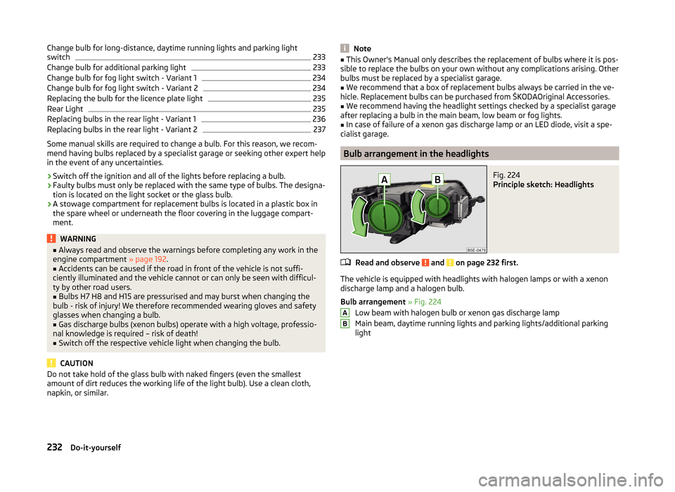
Fig. 224
Principle sketch: Headlights
Read and observe and on page 232 first.
The vehicle is equipped with headlights with halogen lamps or with a xenon
discharge lamp and a halogen bulb.
Bulb arrangement » Fig. 224
Low beam with halogen bulb or xenon gas discharge lamp
Main beam, daytime running lights and parking lights/additional parking
light
AB232Do-it-yourself
Page 236 of 280
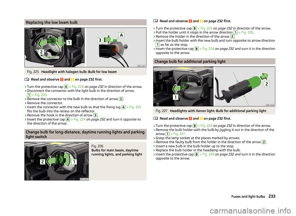
Replacing the low beam bulbFig. 225
Headlight with halogen bulb: Bulb for low beam
Read and observe
and on page 232 first.
›
Turn the protective cap
A
» Fig. 224 on page 232 in direction of the arrow.
›
Disconnect the connector with the light bulb in the direction of arrow
1
» Fig. 225 .
›
Remove the connector to the bulb in the direction of arrow
2
.
›
Remove the connector.
›
Insert the connector with the new bulb so that the fixing lug
A
» Fig. 225
fits the bulb into the recess on the reflector.
›
Remove the hook in the direction of arrow
3
.
›
Insert the protective cap
A
» Fig. 224 on page 232 and turn it opposite to
the direction of the arrow.
Change bulb for long-distance, daytime running lights and parking
light switch
Fig. 226
Bulbs for main beam, daytime
running lights, and parking light
Read and observe and on page 232 first.›
Turn the protective cap
B
» Fig. 224 on page 232 in direction of the arrow.
›
Pull the holder until it stops in the arrow direction
1
» Fig. 226 .
›
Remove the holder in the direction of the arrow
2
.
›
Insert the bulb holder with the new bulb and turn opposite to arrow direction
1
as far as the stop.
›
Insert the protective cap
B
» Fig. 224 on page 232 and turn it in the direction
opposite to the arrow.
Change bulb for additional parking light
Fig. 227
Headlights with Xenon light: Bulb for additional parking light
Read and observe
and on page 232 first.
›
Turn the protective cap
B
» Fig. 224 on page 232 in direction of the arrow.
›
Remove the bulb holder with the bulb by jiggling it out in the direction of the
arrow
1
» Fig. 227 .
›
Grasp the lamp socket at the places marked by arrows.
›
Remove the faulty bulb from the holder in the direction of the arrow
2
.
›
Insert a new bulb in the bulb holder up to the stop.
›
Replace the bulb holder in the headlamp with the bulb.
›
Insert the protective cap
B
» Fig. 224 on page 232 and turn it in the direction
opposite to the arrow.
233Fuses and light bulbs
Page 263 of 280
Index
A
abroad lead-free petrol
189
Abroad Headlights
78
ABS Function
138
Warning light37
ACC149
Control symbols44
Warning light36
Acceptance and recycling of used vehicles180
Accessories177
Adaptive cruise control149
automatic stop-start152
Information messages155
Operation151
Operation Overview152
Radar sensor150
Set/change the desired speed.153
Set time interval level153
special driving conditions154
Start control152
Stop/resume control153
Adaptive headlights (AFS)
74
Adjust Auxiliary heating (auxiliary heating and ventila-tion)
122
Adjusting Belt height
15
Exterior mirrors85
head restraints88
Interior mirror84
seats87
Steering wheel10
the seats electronically87
Adjusting the seats9
Adjusting the seats electronically87
Adjustment Headlight beam
71
Advance warning/emergency brake Warning symbol
45
AFS74
Air-conditioning system Air outlet vents
116
Airbag16
Deactivating21
Deactivating the front passenger airbag21
Deployment16
Front airbag17
Head airbag20
Knee airbag18
Modifications and damage to the airbag system 179
Side airbag
19
Air bag Warning light
38
Airbag system16
Air conditioning116
Air distribution control117
Climatronic119
manual air conditioning119
Air distribution control117
Air outlet vents116
Alarm Switching off
59
Triggering59
Alcantara cleaning
187
Anti-theft alarm system Activating/deactivating
59
Trailer176
Anti-theft wheel bolts217
Antilock Braking System138
Armrest Front
91
Rear91
artificial leather187
Ashtray97
ASR warning light
37
Assistance systems ACC
36
Driving mode160
ESC138
Front Assistant155
High beam assistant75
Lane Assist162
MCB140
TSA140
Assist system ABS
138
Assist systems138
ABS37
Adaptive cruise control149
ASR37
Cruise Control System148
DSR139
EDL139
ESC37
HBA140
HHC140
Park assist144
Parking aid140
ProActive passenger protection161
START-STOP158
TCS139
XDS139
Audio see radio/navigation system
4
Auto-check control47
Automatic driving lamp control73
Automatic gearbox133
Selector lever-emergency unlocking226
Selector lever lock134
Starting-off and driving135
Tiptronic134
Using the selector lever133
260Index
Page 267 of 280
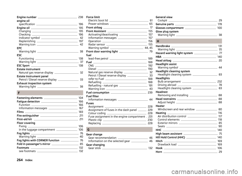
Engine number238
engine oil specification
196
Engine oil195
Changing195
Checking196
Indicator symbol42
Replenishing197
Warning icon42
EPC Warning light
38
ESC Functioning
138
Warning light37
ESC Sport138
Estate instrument Natural gas reserve display
32
Estate Instrument panel Petrol / Diesel reserve display
33
Exhaust inspection system Warning light
38
F
Fastening elements
104
Fatigue detection166
Function166
Information messages167
Films183
Fire extinguisher211
First-aid kit 211
Floor covering Fixing
106
in the luggage compartment106
Fog lights76
Warning light40
Fog lights with CORNER function76
Fold in passenger's mirror85
Footmats132
see footmats132
Force limit Electric boot lid61
Power windows65
Front airbag17
Front Assistant155
Activating/deactivating157
Information messages157
Operation156
Radar sensor155
Warning symbol44, 45
Front door warning light79
fuel lead-free petrol
189
Fuel188
CNG192
Diesel190
Natural gas reserve display32
Petrol / Diesel reserve display33
refer to Fuel188
Refuelling188
Refuelling - natural gas191
Warning icon43
Fuel consumption239
Fuel filter Information messages
44
Fuses Assignment
228
Assignment of fuses in the dash panel229
Colour coding228
Fuse assignment in the engine compartment231
Plastic clip230
Replacing228
G
Gear change Gear recommendation
46
Information on the selected gear46
Gear changing Gear stick
132
General viewCockpit29
Genuine parts178
Glasses compartment100
Glow plug system Warning light
38
H
Handbrake
131
Warning light35
Hazard warning light system77
HBA140
Head airbag20
Headlight assist Warning symbol
44
Headlight cleaning system Headlight cleaning system
83
Headlights Bulb arrangement
232
Driving abroad78
Headlight cleaning system83
Headrest Removing and installing
88
Head restraints88
Adjust height88
Heater Windscreen and rear window
80
Heating116
Air distribution control117
Control elements118
Exterior mirrors85
Seats90
HHC140
High beam assistant75
Hill Hold Control (HHC)140
Hitch169
Drawback load169
Hook106
Horn29
264Index
Page 268 of 280

Hydraulic Brake Assist (HBA)140
I
Ice scrapers
183
Ignition lock127
Immobilizer126
Individual settings Locking
57
Unlocking57
Inertia reel15
Information system45
Compass point display52
Door warning47
Eco-tips52
Gear recommendation46
Lap timer51
MAXI DOT display50
Multifunction display47
Operation46
Outside temperature46
Service interval display53
Stop watch51
Instrument cluster30
Auto-check control47
Counter for distance driven33
Display31
Overview31
Revolutions counter31
Speedometer32
Temperature gauge32
Viewing the charge level of the vehicle battery 34
Warning icons
40
Warning lights34
Interior care185
Natural leather186
Interior light Front
78
Interior lights Rear
79
Interior monitor60
ISOFIX25
J
Jack
212
Maintenance184
Jump-starting220
K
KESSY Locking
56
Unlocking56
Key Locking
55
Starting the engine127
Stopping the engine127
Switching off the ignition127
Switching on the ignition127
Unlocking55
Knee airbag18
L
Lamp failure Warning symbol
43
Lamps Warning symbol
43
Lane Assist162
Activating/deactivating164
Information messages164
Operation163
Warning light39
Lap timer51
Leather Natural leather care
186
LEAVING HOME77
Lever Main beam
73
Turn signal73
Levers Windscreen wipers
82
LichtCOMING HOME / LEAVING HOME77
light travel mode
74
Light Cockpit
78
Fog lights with CORNER function76
High beam assistant75
Replacing bulbs231
tourist light74
lighting entry space
80
Lighting Luggage compartment
103
Lights71
Adaptive headlights (AFS)74
Automatic driving lamp control73
Daylight running72
Fog lights76
Hazard warning light system77
Headlight beam range regulation71
Headlight flasher73
Low beam71
Main beam73
Parking lights71, 78
Rear fog light76
Switching on and off71
Turn signal73
Warning lights34
Locking Individual settings
57
KESSY56
Key55
Remote control55
Locking/unlocking the steering lock Starter button
128
Locking and unlocking the vehicle from the in- side
58
Locking the door without a locking cylinder Emergency
226
265Index