gearbox SKODA OCTAVIA 2014 3.G / (5E) Owner's Manual
[x] Cancel search | Manufacturer: SKODA, Model Year: 2014, Model line: OCTAVIA, Model: SKODA OCTAVIA 2014 3.G / (5E)Pages: 280, PDF Size: 35.53 MB
Page 5 of 280
Table of Contents
On-board literature4
Notes
5
Structure and more information about the
Owner's manual
6
Abbreviations
Safety
Passive Safety
8
General information
8
Correct and safe seated position
9
Seat belts
12
Using seat belts
12
Inertia reel and belt pretensioners
15
Airbag system
16
Description of the airbag system
16
Airbag overview
17
Deactivating airbags
21
Transporting children safely
22
Child seat
22
Fastening elements
25
Using the system
Cockpit
29
Overview
28
Instruments and warning lights
30
Instrument cluster
30
Warning lights
34
Warning icons in the display
40
Information system
45
Driver information system
45
Driving data (Multifunction display)
47MAXI DOT display50Service interval display53
Unlocking and opening
54
Unlocking and locking
54
Anti-theft alarm system
59
Luggage compartment lid
60
Electric boot lid
61
Power windows
64
Mechanical windows
66
Panorama sliding-/tilting roof - Version 1
67
Panorama sliding-/tilting roof - Version 2
68
Lights and visibility
71
Lights
71
Interior lights
78
Visibility
80
Windscreen wipers and washers
81
Rear mirror
83
Seats and head restraints
86
Seats and head restraints
86
Seat features
90
Transporting and practical equipment
94
Useful equipment
94
Luggage compartment
103
Variable loading floor in the luggage
compartment (Estate)
110
Net partition
112
Roof rack
113
Heating and air conditioning
116
Heating, ventilation, cooling
116
Auxiliary heating (auxiliary heating and
ventilation)
121
Communication
124
SmartGate
124Driving
Starting-off and Driving126
Starting and stopping the engine using the key
126
Starting or stopping the engine by pressing
button
128
Brakes and parking
130
Manual shifting of gears and pedals
132
Automatic gearbox
133
Retraction and economical driving
136
Driving through water and driving off of
made-up roads
137
Assist systems
138
Braking and stabilisation systems
138
Parking aid
140
Optical Parking Assistant (rear view camera)
143
Park assist
144
Cruise Control System
148
Adaptive Cruise Control (ACC)
149
Front Assistant
155
START-STOP
158
Selection of travel mode (Driving Mode
Selection)
160
ProActive passenger protection
161
Lane Assist
162
Traffic sign recognition
164
Fatigue detection (break recommendation)
166
Tyre pressure monitoring
167
Hitch and trailer
169
Hitch
169
Trailer
1742Table of Contents
Page 10 of 280
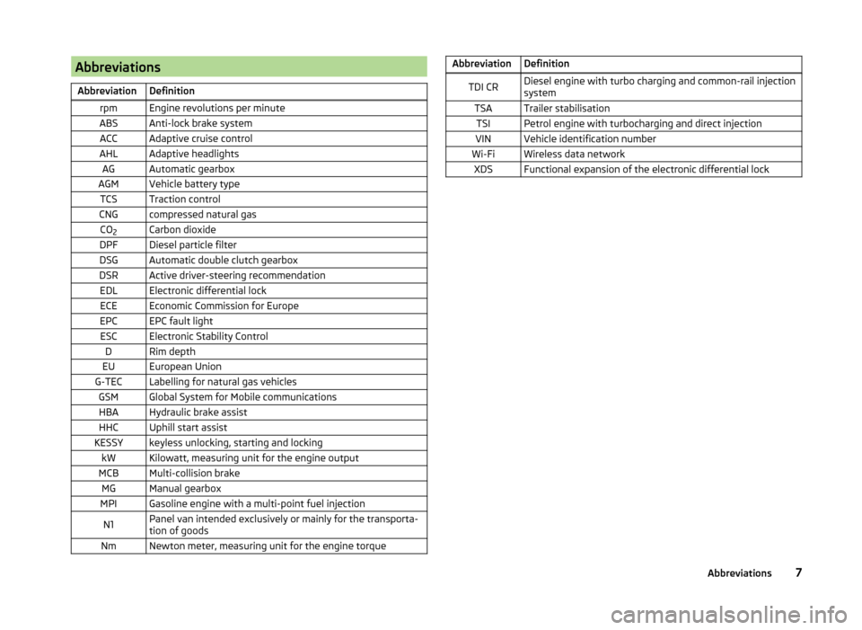
AbbreviationsAbbreviationDefinitionrpmEngine revolutions per minuteABSAnti-lock brake systemACCAdaptive cruise controlAHLAdaptive headlightsAGAutomatic gearboxAGMVehicle battery typeTCSTraction controlCNGcompressed natural gasCO2Carbon dioxideDPFDiesel particle filterDSGAutomatic double clutch gearboxDSRActive driver-steering recommendationEDLElectronic differential lockECEEconomic Commission for EuropeEPCEPC fault lightESCElectronic Stability ControlDRim depthEUEuropean UnionG-TECLabelling for natural gas vehiclesGSMGlobal System for Mobile communicationsHBAHydraulic brake assistHHCUphill start assistKESSYkeyless unlocking, starting and lockingkWKilowatt, measuring unit for the engine outputMCBMulti-collision brakeMGManual gearboxMPIGasoline engine with a multi-point fuel injectionN1Panel van intended exclusively or mainly for the transporta-
tion of goodsNmNewton meter, measuring unit for the engine torqueAbbreviationDefinitionTDI CRDiesel engine with turbo charging and common-rail injection
systemTSATrailer stabilisationTSIPetrol engine with turbocharging and direct injectionVINVehicle identification numberWi-FiWireless data networkXDSFunctional expansion of the electronic differential lock7Abbreviations
Page 32 of 280
Using the system
Cockpit
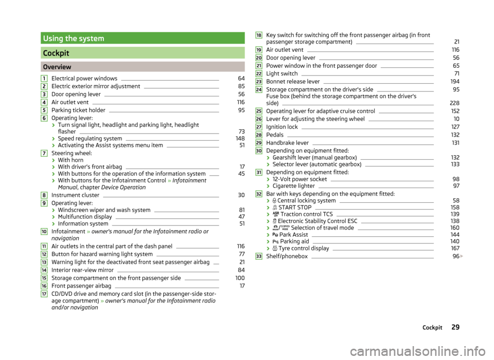
OverviewElectrical power windows
64
Electric exterior mirror adjustment
85
Door opening lever
56
Air outlet vent
116
Parking ticket holder
95
Operating lever:
› Turn signal light, headlight and parking light, headlight
flasher
73
› Speed regulating system
148
›Activating the Assist systems menu item
51
Steering wheel:
› With horn
› With driver’s front airbag
17
›With buttons for the operation of the information system
45
›With buttons for the Infotainment Control
» Infotainment
Manual , chapter Device Operation
Instrument cluster
30
Operating lever: › Windscreen wiper and wash system
81
›Multifunction display
47
›Information system
51
Infotainment
» owner's manual for the Infotainment radio or
navigation
Air outlets in the central part of the dash panel
116
Button for hazard warning light system
77
Warning light for the deactivated front seat passenger airbag
21
Interior rear-view mirror
84
Storage compartment on the front passenger side
100
Front passenger airbag
17
CD/DVD drive and memory card slot (in the passenger-side stor-
age compartment) » owner's manual for the Infotainment radio
and/or navigation
1234567891011121314151617Key switch for switching off the front passenger airbag (in front
passenger storage compartment)21
Air outlet vent
116
Door opening lever
56
Power window in the front passenger door
65
Light switch
71
Bonnet release lever
194
Storage compartment on the driver's side
95
Fuse box (behind the storage compartment on the driver's
side)
228
Operating lever for adaptive cruise control
152
Lever for adjusting the steering wheel
10
Ignition lock
127
Pedals
132
Handbrake lever
131
Depending on equipment fitted:
› Gearshift lever (manual gearbox)
132
›Selector lever (automatic gearbox)
133
Depending on equipment fitted:
› 12-Volt power socket
98
›Cigarette lighter
97
Bar with keys depending on the equipment fitted:
›
Central locking system
58
›
START STOP
158
›
Traction control TCS
139
›
Electronic Stability Control ESC
138
›
/
Selection of travel mode
160
›
Park Assist
144
›
Parking aid
140
›
Tyre control display
167
Shelf/phonebox
96
1819202122232425262728293031323329Cockpit
Page 34 of 280
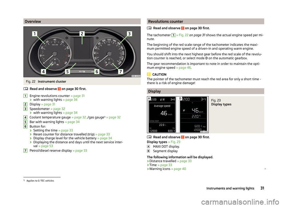
OverviewFig. 22
Instrument cluster
Read and observe
on page 30 first.
Engine revolutions counter » page 31
› with warning lights
» page 34
Display » page 31
Speedometer » page 32
› with warning lights
» page 34
Coolant temperature gauge » page 32 ,/gas gauge 1)
» page 32
Bar with warning lights » page 34
Button for:
› Setting the time
» page 33
› Reset counter for distance travelled (trip)
» page 33
› Display charge level for the vehicle battery
» page 34
› Displaying the distance and days until the next service inter-
val » page 53
Petrol/diesel reserve display » page 33
1234567Revolutions counter
Read and observe
on page 30 first.
The tachometer
1
» Fig. 22 on page 31 shows the actual engine speed per mi-
nute.
The beginning of the red scale range of the tachometer indicates the maxi-
mum permitted engine speed of a driven-in and operating warm engine.
You should shift into the next highest gear before the red scale of the revolu- tion counter is reached, or select mode D on the automatic gearbox.
The gear recommendation is important to note in order to maintain the opti-
mum engine speed » page 46.
CAUTION
The pointer of the tachometer must reach the red area for only a short time -
there is a risk of engine damage!
Display
Fig. 23
Display types
Read and observe on page 30 first.
Display types » Fig. 23
MAXI DOT display.
Segment display
The following information will be displayed.
› Distance travelled
» page 33
› Time
» page 33
› Warning icons
» page 40
1)
Applies to G-TEC vehicles
31Instruments and warning lights
Page 38 of 280
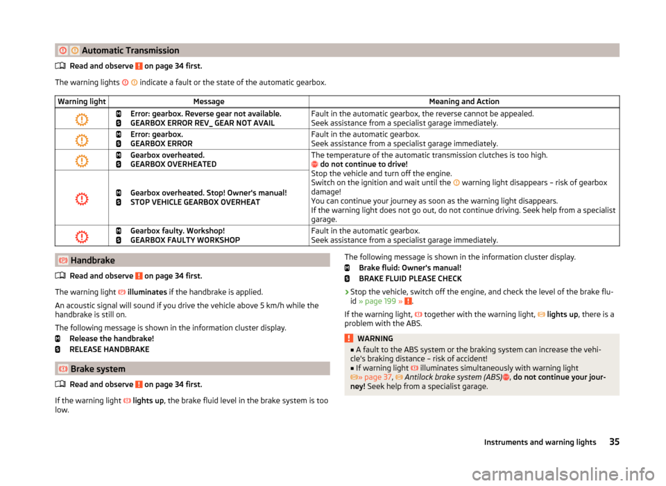
Automatic TransmissionRead and observe on page 34 first.
The warning lights
indicate a fault or the state of the automatic gearbox.
Warning lightMessageMeaning and Action
Error: gearbox. Reverse gear not available.
GEARBOX ERROR REV_ GEAR NOT AVAILFault in the automatic gearbox, the reverse cannot be appealed.
Seek assistance from a specialist garage immediately.
Error: gearbox.
GEARBOX ERRORFault in the automatic gearbox.
Seek assistance from a specialist garage immediately.
Gearbox overheated.
GEARBOX OVERHEATEDThe temperature of the automatic transmission clutches is too high.
do not continue to drive!
Stop the vehicle and turn off the engine.
Switch on the ignition and wait until the
warning light disappears – risk of gearbox
damage!
You can continue your journey as soon as the warning light disappears.
If the warning light does not go out, do not continue driving. Seek help from a specialist
garage.
Gearbox overheated. Stop! Owner's manual!
STOP VEHICLE GEARBOX OVERHEAT
Gearbox faulty. Workshop!
GEARBOX FAULTY WORKSHOPFault in the automatic gearbox.
Seek assistance from a specialist garage immediately. Handbrake
Read and observe
on page 34 first.
The warning light
illuminates if the handbrake is applied.
An acoustic signal will sound if you drive the vehicle above 5 km/h while the
handbrake is still on.
The following message is shown in the information cluster display. Release the handbrake!
RELEASE HANDBRAKE
Brake system
Read and observe
on page 34 first.
If the warning light
lights up , the brake fluid level in the brake system is too
low.
The following message is shown in the information cluster display.
Brake fluid: Owner's manual!
BRAKE FLUID PLEASE CHECK›
Stop the vehicle, switch off the engine, and check the level of the brake flu-
id » page 199 » .
If the warning light,
together with the warning light,
lights up , there is a
problem with the ABS.
WARNING■ A fault to the ABS system or the braking system can increase the vehi-
cle's braking distance – risk of accident!■
If warning light
illuminates simultaneously with warning light
» page 37 ,
Antilock brake system (ABS)
, do not continue your jour-
ney! Seek help from a specialist garage.
35Instruments and warning lights
Page 46 of 280
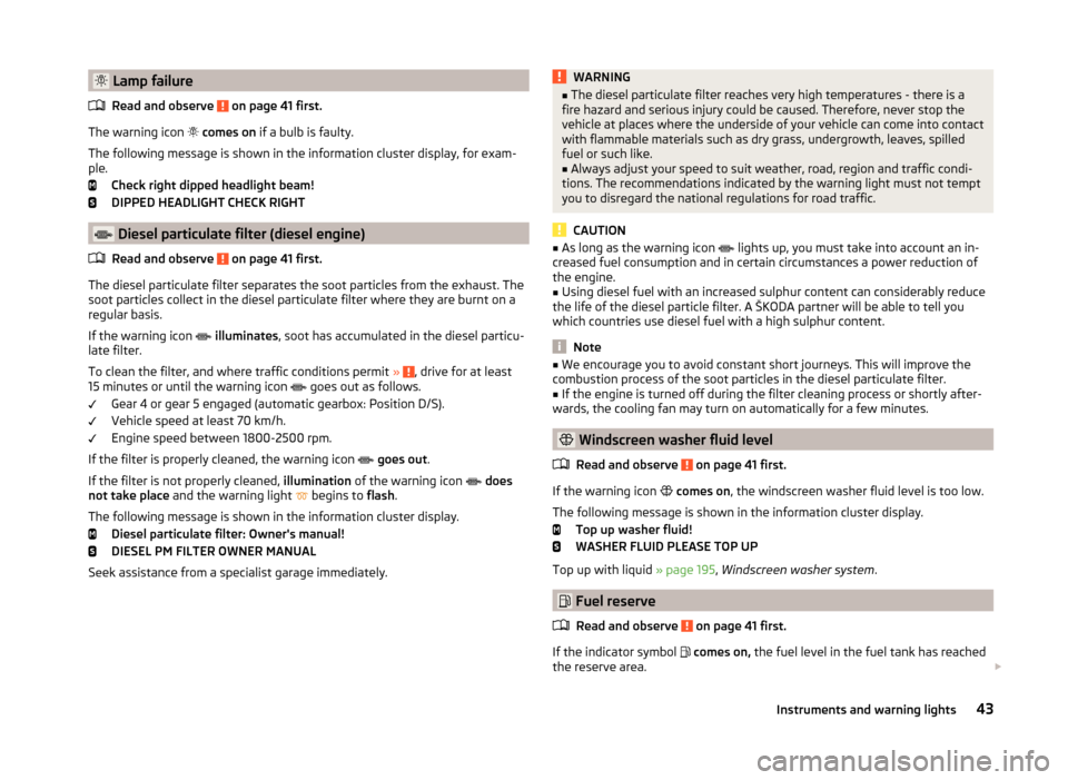
Lamp failureRead and observe
on page 41 first.
The warning icon
comes on if a bulb is faulty.
The following message is shown in the information cluster display, for exam-
ple.
Check right dipped headlight beam!
DIPPED HEADLIGHT CHECK RIGHT
Diesel particulate filter (diesel engine)
Read and observe
on page 41 first.
The diesel particulate filter separates the soot particles from the exhaust. The
soot particles collect in the diesel particulate filter where they are burnt on a
regular basis.
If the warning icon
illuminates , soot has accumulated in the diesel particu-
late filter.
To clean the filter, and where traffic conditions permit »
, drive for at least
15 minutes or until the warning icon goes out as follows.
Gear 4 or gear 5 engaged (automatic gearbox: Position D/S).
Vehicle speed at least 70 km/h.
Engine speed between 1800-2500 rpm.
If the filter is properly cleaned, the warning icon
goes out .
If the filter is not properly cleaned, illumination of the warning icon
does
not take place and the warning light
begins to
flash.
The following message is shown in the information cluster display. Diesel particulate filter: Owner's manual!
DIESEL PM FILTER OWNER MANUAL
Seek assistance from a specialist garage immediately.
WARNING■ The diesel particulate filter reaches very high temperatures - there is a
fire hazard and serious injury could be caused. Therefore, never stop the
vehicle at places where the underside of your vehicle can come into contact
with flammable materials such as dry grass, undergrowth, leaves, spilled
fuel or such like.■
Always adjust your speed to suit weather, road, region and traffic condi-
tions. The recommendations indicated by the warning light must not tempt
you to disregard the national regulations for road traffic.
CAUTION
■ As long as the warning icon lights up, you must take into account an in-
creased fuel consumption and in certain circumstances a power reduction of
the engine.■
Using diesel fuel with an increased sulphur content can considerably reduce
the life of the diesel particle filter. A ŠKODA partner will be able to tell you
which countries use diesel fuel with a high sulphur content.
Note
■ We encourage you to avoid constant short journeys. This will improve the
combustion process of the soot particles in the diesel particulate filter.■
If the engine is turned off during the filter cleaning process or shortly after-
wards, the cooling fan may turn on automatically for a few minutes.
Windscreen washer fluid level
Read and observe
on page 41 first.
If the warning icon
comes on , the windscreen washer fluid level is too low.
The following message is shown in the information cluster display. Top up washer fluid!
WASHER FLUID PLEASE TOP UP
Top up with liquid » page 195, Windscreen washer system .
Fuel reserve
Read and observe
on page 41 first.
If the indicator symbol
comes on, the fuel level in the fuel tank has reached
the reserve area.
43Instruments and warning lights
Page 48 of 280
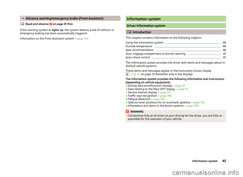
Advance warning/emergency brake (Front Assistant)Read and observe
on page 41 first.
If the warning symbol
lights up , the system detects a risk of collision or
emergency braking has been automatically triggered.
Information on the Front Assistant system » page 155.
Information system
Driver information system
Introduction
This chapter contains information on the following subjects:
Using the information system
46
Outside temperature
46
Gear recommendation
46
Door, luggage compartment or bonnet warning
47
Auto-check control
47
The information system provides the driver with alerts and messages about in-
dividual vehicle systems.
These alerts and messages appear in the instrument cluster display
2
» Fig. 22 on page 31 (hereafter only in the display).
The information system provides the following information and instructions
(depending on vehicle equipment).
› Driving data (multifunction display)
» page 47.
› Data relating to the Maxi DOT display
» page 51.
› Service interval display
» page 53.
› Traffic sign recognition
» page 164.
› Fatigue detection
» page 166.
› Selector lever positions for an automatic gearbox
» page 133.
› Information and alerts in the Assist systems
» page 138.
WARNINGConcentrate fully at all times on your driving! As the driver, you are fully re-
sponsible for the operation of your vehicle.45Information system
Page 59 of 280
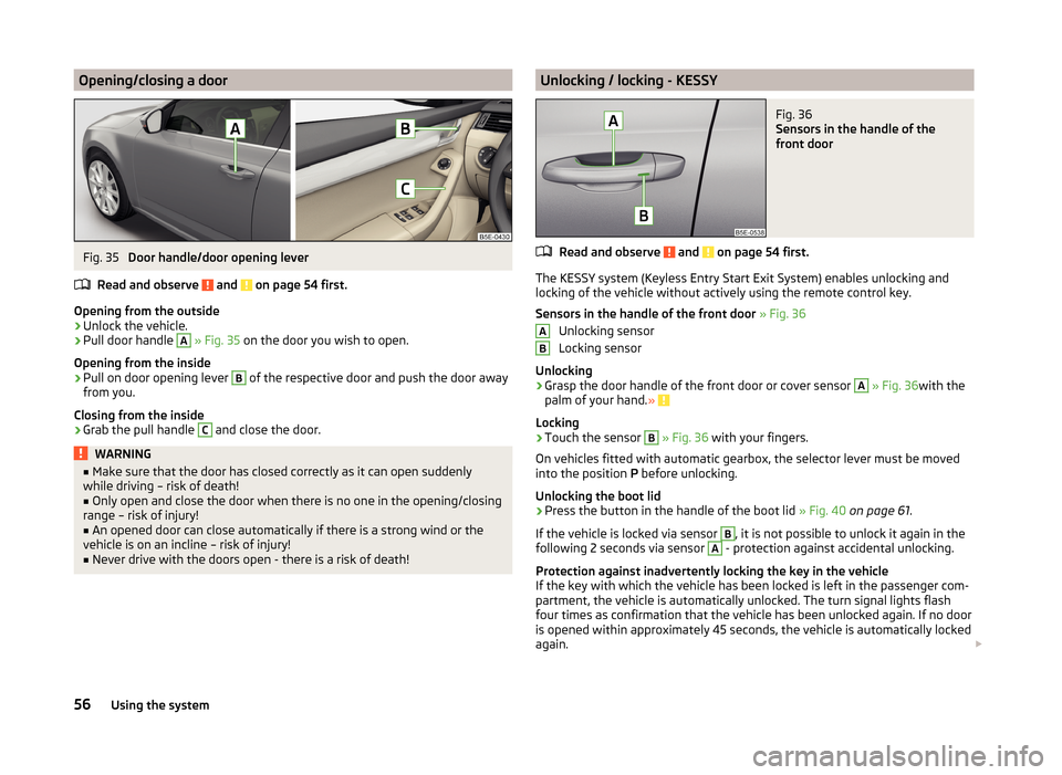
Opening/closing a doorFig. 35
Door handle/door opening lever
Read and observe
and on page 54 first.
Opening from the outside
›
Unlock the vehicle.
›
Pull door handle
A
» Fig. 35 on the door you wish to open.
Opening from the inside
›
Pull on door opening lever
B
of the respective door and push the door away
from you.
Closing from the inside
›
Grab the pull handle
C
and close the door.
WARNING■ Make sure that the door has closed correctly as it can open suddenly
while driving – risk of death!■
Only open and close the door when there is no one in the opening/closing
range – risk of injury!
■
An opened door can close automatically if there is a strong wind or the
vehicle is on an incline – risk of injury!
■
Never drive with the doors open - there is a risk of death!
Unlocking / locking - KESSYFig. 36
Sensors in the handle of the
front door
Read and observe and on page 54 first.
The KESSY system (Keyless Entry Start Exit System) enables unlocking and
locking of the vehicle without actively using the remote control key.
Sensors in the handle of the front door » Fig. 36
Unlocking sensor
Locking sensor
Unlocking
›
Grasp the door handle of the front door or cover sensor
A
» Fig. 36 with the
palm of your hand. »
Locking
›
Touch the sensor
B
» Fig. 36 with your fingers.
On vehicles fitted with automatic gearbox, the selector lever must be moved
into the position P before unlocking.
Unlocking the boot lid
›
Press the button in the handle of the boot lid » Fig. 40 on page 61 .
If the vehicle is locked via sensor
B
, it is not possible to unlock it again in the
following 2 seconds via sensor
A
- protection against accidental unlocking.
Protection against inadvertently locking the key in the vehicle
If the key with which the vehicle has been locked is left in the passenger com-
partment, the vehicle is automatically unlocked. The turn signal lights flash
four times as confirmation that the vehicle has been unlocked again. If no door
is opened within approximately 45 seconds, the vehicle is automatically locked
again.
AB56Using the system
Page 132 of 280
Under certain circumstances (e.g. after switching off the ignition and opening
the driver's door), the steering is enabled only when the ignition is switched on
or the engine is started.WARNINGNever let the vehicle roll with locked steering lock - there is a risk of acci-
dent!
Switching ignition on / off
Read and observe
and on page 128 first.
›
Press the button » Fig. 130 on page 128 briefly.
The ignition is switched on or off.
On vehicles fitted with a manual gearbox, the clutch pedal must not be de-
pressed while switching the ignition on or off, otherwise the system would try
to start.
On vehicles fitted with a automatic gearbox, the brake pedal must not be de-
pressed while switching the ignition on or off, otherwise the system would try
to start.
If the driver's door is opened while the igition is on, an audible signal sounds
and the following message appears in the instrument cluster display.
Ignition on!
IGNITION STILL ON
When leaving the vehicle always switch off the ignition.
Starting the engine
Read and observe
and on page 128 first.
Procedure for starting the engine
›
Firmly apply the handbrake.
›
For vehicles with manual transmission , shift gear stick to neutral, depress
the clutch pedal and hold it there until the engine starts.
›
On vehicles with automatic transmission , place the selector lever in position
P or N and depress the brake pedal until the engine starts.
›
Press the starter button » Fig. 130 on page 128 briefly – the engine starts au-
tomatically.
In vehicles with diesel engines after pressing the button, the glow plug warn-
ing light lights up. The engine can be started after the indicator light goes
out.
Note
■ The engine running noises may louder at first be louder for a short time after
starting the cold engine. This is quite normal and is not an operating problem.■
You should not switch on any major electrical components during the heat-
ing period otherwise the vehicle battery will be drained unnecessarily.
Switching off the engine
Read and observe
and on page 128 first.
Switching off
›
Stop the vehicle » page 132, Parking .
›
Press the button » Fig. 130 on page 128 briefly.
The engine and the ignition are switched off simultaneously.
Emergency shutdown
If necessary, the engine in exceptional cases may also be turned off while driv-
ing.
›
Press the starter button » Fig. 130 on page 128 for longer than 1 second or
twice within 1 second.
After the emergency stop of the engine, the steering lock will remain un-
locked.
CAUTION
Do not switch the engine off immediately at the end of your journey after the
engine has been operated over a prolonged period at high loads but leave it to
run at an idling speed for about 1 minute. This prevents any possible accumula-
tion of heat when the engine is switched off.
Note
After switching off the ignition, the radiator fan may intermittently continue to
operate for approx. 10 minutes.129Starting-off and Driving
Page 135 of 280
The handbrake warning is activated if the vehicle is driven at a speed of more
than around 5 km/h for more than 3 seconds.WARNINGPlease note that the handbrake must be fully released. A handbrake which
is only partially released can result in the rear brakes overheating. This can
have a negative effect on the operation of the brake system – risk of acci-
dent!
Parking
Read and observe
and on page 130 first.
When stopping and parking, look for a place with a suitable surface » .
Only carry out the activities while parking in the specified order.
›
Bring the vehicle to a stop and depress the brake pedal.
›
Firmly apply the handbrake.
›
On vehicles with automatic transmission place the selector lever in the P po-
sition.
›
Switch off the engine.
›
For vehicles with manual transmission , select 1st gear or reverse gear
›
Release the brake pedal.
WARNINGThe parts of the exhaust system can become very hot. Therefore, never
stop the vehicle at places where the underside of your vehicle can come in-
to contact with flammable materials such as dry grass, undergrowth,
leaves, spilled fuel or such like. - Risk of fire and serious injury can occur!
Manual shifting of gears and pedals
Introduction
This chapter contains information on the following subjects:
Manual gear changing
132
Pedals
132Manual gear changingFig. 133
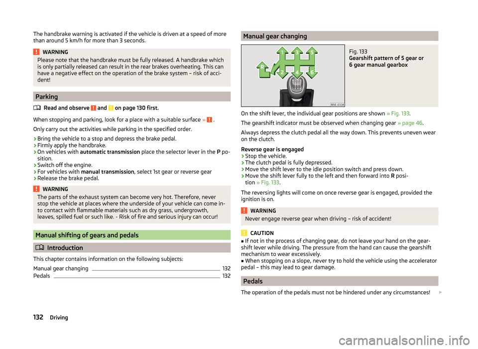
Gearshift pattern of 5 gear or
6 gear manual gearbox
On the shift lever, the individual gear positions are shown » Fig. 133.
The gearshift indicator must be observed when changing gear » page 46.
Always depress the clutch pedal all the way down. This prevents uneven wear
on the clutch.
Reverse gear is engaged
›
Stop the vehicle.
›
The clutch pedal is fully depressed.
›
Move the shift lever to the idle position switch and press down.
›
Move the shift lever fully to the left and then forward into R posi-
tion » Fig. 133 .
The reversing lights will come on once reverse gear is engaged, provided the ignition is on.
WARNINGNever engage reverse gear when driving – risk of accident!
CAUTION
■ If not in the process of changing gear, do not leave your hand on the gear-
shift lever while driving. The pressure from the hand can cause the gearshift
mechanism to wear excessively.■
When stopping on a slope, never try to hold the vehicle using the accelerator
pedal – this may lead to gear damage.
Pedals
The operation of the pedals must not be hindered under any circumstances!
132Driving