width SKODA OCTAVIA 2014 3.G / (5E) Owner's Manual
[x] Cancel search | Manufacturer: SKODA, Model Year: 2014, Model line: OCTAVIA, Model: SKODA OCTAVIA 2014 3.G / (5E)Pages: 280, PDF Size: 35.53 MB
Page 75 of 280

Turn switchSwitching off lights (except daytime running lights)Switching lights on and off automatically » page 73
Switching on the parking light or parking lights » page 78
Switching on the low beam
Pull switch Switching on the front fog light » page 76
Switching on the rear fog light » page 76
Headlight beam range regulation
Turning the dial B
» Fig. 50 from the position
in
means the headlight
beam range is gradually adjusted, thereby shortening the beam of light.
The positions of the width of illumination correspond approximately to the fol-
lowing car load.
Front seats occupied, boot empty
All seats occupied, boot empty
All seats occupied, boot loaded
Driver seat occupied, boot loaded
We recommend you adjust the headlight beam when the low beam is switched
on.
Bi-Xenon headlights
The Bi-Xenon bulbs adapt automatically to the load and driving state of the
vehicle when the ignition is switched on and when driving. Vehicles that are
equipped with Bi-Xenon headlights do not have a manual headlight range ad-
justment control.
WARNINGAlways adjust the headlight beam to satisfy the following conditions.■The vehicle does not dazzle other road users, especially oncoming vehi-
cles.■
The beam range is sufficient for safe driving.
Note
■ The light switch is in position or and the ignition is turned off, the low
beam is switched off automatically and the status light is lit. The side light
goes out after the ignition key is removed.■
If there is a fault in the light switch, the low beam comes on automatically.
Daylight running lights (DAY LIGHT)
Read and observe
on page 71 first.
The daytime running lights (the only function) provides the lighting of the front
vehicle range.
The daytime running lights are switched on automatically if the following
conditions are met.
The light switch is in the position
or
» Fig. 50 on page 71 .
The ignition is switched on.
The parking aid is activated.
Activating/deactivating daytime operation on vehicles with Infotainment
The function can be activated/deactivated in the Infotainment » Infotainment
manual , chapter Vehicle settings (CAR button) .
Deactivating on vehicles without Infotainment
›
Switch off the ignition.
›
Pull the turning signal and main beam lever ( » Fig. 51 on page 73 ) towards
the steering wheel, push down and hold in this position.
›
Switch on the ignition.
›
Hold the lever in this position for at least. 3 seconds after switching on the
ignition.
Activating on vehicles without Infotainment
›
Switch off the ignition.
›
Pull the turning signal and main beam lever towards the steering wheel,
push it up and hold it in this position.
›
Switch on the ignition.
›
Hold the lever in this position for at least. 3 seconds after switching on the
ignition.
WARNINGWhen the daytime running light is switched on, the side lights (neither at
the front or rear) and the number plate lights are not lit. Therefore always
switch on the low beam when the visibility is poor.72Using the system
Page 91 of 280

The adjusted driver's seat position can be set in the memory of the
seat » page 89 or the remote control key » page 89.
Note
If the setting procedure is interrupted, you will need to press the button again.
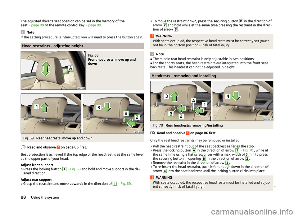
Head restraints - adjusting height
Fig. 68
Front headrests: move up and
down
Fig. 69
Rear headrests: move up and down
Read and observe
on page 86 first.
Best protection is achieved if the top edge of the head rest is at the same level as the upper part of your head.
Adjust front support
›
Press the locking button
A
» Fig. 68 and hold and move support in the de-
sired direction.
Adjust rear support
›
Grasp the restraint and move upwards in the direction of
1
» Fig. 69 .
›To move the restraint
down, press the securing button B in the direction of
arrow 2 and hold while at the same time pressing the restraint in the direc-
tion of arrow 3
.
WARNINGWith seats occupied, the respective head rests must be correctly set (must
not be in the bottom position) - risk of fatal injury!
Note
■ The middle rear head restraint is only adjustable in two positions.■For the sports seats, the head restraints are integrated into the front seat
backrests. This headrest can not be adjusted in height.
Headrests - removing and installing
Fig. 70
Rear headrests: removing/installing
Read and observe
on page 86 first.
Only the real head restraints may be removed or installed.
›
Pull the head restraint out of the seat backrest as far as the stop.
›
Press the locking button
A
in the direction of arrow
1
» Fig. 70 , while at
the same time using a flat screwdriver with a max. width of 5 mm to press
the securing button in opening
B
in the direction of arrow
2
.
›
Remove the restraint in the direction of arrow
3
.
›
To re-insert the head restraint, push it far enough down in the direction of
arrow
4
into the seat backrest until the locking button clicks into place.
WARNINGWith seats occupied, the respective head rests must be installed and adjus- ted correctly - risk of fatal injury! 88Using the system
Page 147 of 280

The area behind the vehicle is displayed when the following conditions are
met.
The ignition is switched on.
Reverse gear is engaged. 1)
The luggage compartment lid is completely closed.
The vehicle is not travelling at more than about 10 km/h.
Note
■ The display can be interrupted by pressing the symbol key » Fig. 138 on
page 141 .■
After disengaging the reverse gear, automatic display of the parking aid is
carried out (variant 2, 3) » page 141.
Orientation lines and function keys
Fig. 143
Infotainment display: Orientation lines / function keys
Read and observe
and on page 143 first.
Orientation lines are shown along with the monitored area behind the vehicle
in the display.
Distance of the orientation lines behind the vehicle » Fig. 143
The distance is about 40 cm (safety distance limit).
The distance is approximately 100 cm.
The distance is approximately 200 cm.
The distance between the lateral guide bars corresponds to the vehicle width including mirrors.
ABCFunction keys » Fig. 143
Turns off the display of the area behind the vehicle.
Display settings - brightness, contrast, colour. Switch the audible parking signals on/off.
Enabling and reduced park assistance display.
Change to park assistance display.
CAUTION
The objects shown in the display can be closer or even further away than they
appear. This is especially the case in the following situations.■
Protruding objects, such as a hitch, the rear of a truck and the like.
■
When driving from a horizontal surface into a slope or a depression.
■
When driving from a slope or a depression onto a horizontal surface.
Note
The orientation lines are immobile, and therefore the spacing of the bars be-
hind the vehicle will vary, depending on the vehicle load state and the road in-
clination.
Park assist
Introduction
This chapter contains information on the following subjects:
Functioning
145
Finding a parking space
145
Parking
146
Departing from a parallel parking space
147
Automatic emergency braking
147
Information messages
147
Park Assist (in the following referred to as the system) helps drivers park in
suitable parallel and perpendicular parking places and also to manoeuvre out
of parallel parking spaces.
The system takes over the steering movements when parking or driving out of
the parking space, the driver operates the pedals as well as the gear lever.
1)
The area behind the vehicle can be displayed for a few seconds more after disengaging the reverse gear.
144Driving
Page 167 of 280

The boundary lines are clearly visible (appropriate longitudinal markings).
The boundary line of at least one side of the lane is detected.
The driver's hands are on the steering wheel.
The lane is more than 2.5 m in width.
If the turn signal is switched on prior to driving over the boundary line (e.g.
when making a turn), no steering intervention takes place when the vehicle
approaches the boundary line. The system regards the situation as an inten-
ded lane change.
Warning lights in the instrument clusterWarning lightMeaningThe system is active, but not ready to intervene.The system is active and ready to intervene or is currently
intervening.
Adaptive lane assist
Adaptive lane assist helps to keep the vehicle in the position between the
boundary lines selected by the driver, by means of steering intervention.
If the system detects only one boundary line, it will help to maintain the selec-
ted proximity from said boundary line.
If the proximity to the detected boundary line is changed, the system quickly
adapts and maintains the newly-selected position.
WARNINGThe function of adaptive lane guidance Assist system may be restricted
when driving e.g. over rutted roads, on a slope, or if there are lateral winds.
Activating/deactivating
Read and observe
and on page 163 first.
The activation or deactivation of the system can be carried out in one of two
ways.
› In the
Assist systems menu item in the instrument cluster display » page 51,
Menu item wizard .
› In Infotainment
» Infotainment operating instructions , chapter Vehicle set-
tings (CAR button) .
Adaptive tracking can also be enabled or disabled In Infotainment.
Information messages
Read and observe
and on page 163 first.
The information messages are shown in the instrument cluster display. Lane Assist not available. No sensor view.
The windscreen is dirty, iced over or misted up in the camera viewing range.
Clean the windscreen or remove the obstacles.
Lane Assist currently not available.
The system has limited functionality due to a temporary error. Try to re-acti-
vate the machine.
Error: Lane Assist
There is a system error. Seek help from a specialist garage. Lane Assist: Take over steering!
The system has detected that there are no hands on the steering wheel. In
this case, the Assist system is not ready to intervene. Place your hands on the
steering wheel.
Traffic sign recognition
Introduction
This chapter contains information on the following subjects:
Function
165
Additional display
166
Traffic sign display when towing a trailer
166
Information messages
166
The traffic sign recognition system (hereinafter referred to only as system)
shows certain traffic signs on the display of the instrument cluster.
WARNING■ The system only serves to support and does not relieve the driver of the
responsibility for the vehicle operation.■
Vertical traffic signs must always take precedence over the traffic signs
shown in the display. The driver is always responsible for correctly assess-
ing the traffic situation.
164Driving
Page 210 of 280

Manufacturer-approved tyre variants
Introduction
This chapter contains information on the following subjects:
Explanation of the tyre labelling
207
Octavia
208
Octavia GreenLine
208
Octavia G-TEC
209
Octavia Scout
209
Octavia RS
209
Approved tyre variants must be selected firstly for the model variant (Octavia
GreenLine, Octavia Scout etc.) and then according to the engine size of your
vehicle. If the model variant of your vehicle cannot be found in a separate
module, then the approved tyre variants must be selected according to the en-
gine size of your vehicle in module » page 208, Octavia .
Only fit radial tyres of the same type, size (rolling circumference) and the same
tread pattern on one axle on all 4 wheels.
When fitting new tyres, the tyres must be replaced axle by axle.
The information listed in the table corresponds to the information available at
the time of going to press.
The approved tyre/rim combinations for your vehicle can be found in the sales
and technical vehicle documentation.
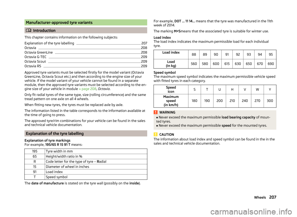
Explanation of the tyre labelling
Explanation of tyre markings
For example, 195/65 R 15 91 T means:
195Tyre width in mm65Height/width ratio in %RCode letter for the type of tyre – Radial15Diameter of wheel in inches91Load indexTSpeed symbol
The date of manufacture is stated on the tyre wall (possibly on the inside).
For example, DOT ... 11 14... means that the tyre was manufactured in the 11th
week of 2014.
The marking M+Smeans that the associated tyre is suitable for winter use.
Load index
The load index indicates the maximum permissible load for each individual
tyre.Load index8889909192939495Load
(In kg)560580600615630650670690
Speed symbol
The maximum speed symbol indicates the maximum permissible vehicle speed
with fitted tyres in each category.
Speed iconSTUHVWYMaximum speed
(in km/h)180190200210240270300WARNING■ Never exceed the maximum permissible load bearing capacity of moun-
ted tyres.■
Never exceed the maximum permissible speed for the mounted tyres.
CAUTION
The information about load index and speed symbol can be found in the in the
sales and technical vehicle documentation.207Wheels
Page 243 of 280

Dimensions - OctaviaFig. 236
Principle sketch: Vehicle dimensions
Vehicle dimensions for operating weight without driver (in mm)
» Fig. 23 6SpecificationOctaviaOctavia 4x4Octavia RSA
Height
Basic dimension1461 a)
/1458 b)1460a)
/1459 b)1449Vehicles with off-road package.1476a)
/1474 b)1475a)
/1474 b)-Vehicles with SPORT package1446a)
/1444 b)--G-TEC vehicles1461--BFront track
» table on page 241CWidth181418141814DRear track » table on page 241EWidth including exterior mirror201720172017F
Clearance
Basic dimension140138128Vehicles with off-road package.155154-Vehicles with SPORT package125--G-TEC vehicles140-- 240Technical data
Page 245 of 280

Dimensions - Octavia CombiFig. 237
Schematic diagram: Vehicle dimensions
Vehicle dimensions for operating weight without driver (in mm)
» Fig. 237SpecificationOctavia EstateOCTAVIA Estate 4x4OCTAVIA Estate RSOCTAVIA EstateSCOUTA
Height
Basic dimension1465 a)
/1463 b)1465a)
/1463 b)14521531Vehicles with off-road package.1480a)
/1478 b)1480a)
/1478 b)--Vehicles with SPORT package1450a)
/1448 b)---G-TEC vehicles1465---BFront track
» table on page 243CWidth1814181418141814DRear track » table on page 243EWidth including exterior mirror2017201720172017F
Clearance
Basic dimension140139127171Vehicles with off-road package.155154- Vehicles with SPORT package125---G-TEC vehicles140--- 242Technical data
Page 273 of 280

Tyres204
Explanation of the labelling207
new136
see wheels207
Tyre pressure204
Wear205
Wear indicator206
Tyre size207
see wheels207
U
Under-body Vehicle care
185
Under-body protection185
Unlocking Individual settings
57
KESSY56
Key55
Remote control55
Unlocking and locking54
Used vehicles Acceptance and recycling
180
Useful equipment 230-volt socket
101
Ashtray97
Car park ticket holder95
Cigarette lighter97
Clothes hook101
Cup holders96
Glasses compartment100
Multimedia holder99
Removable through-loading bag102
Seat backrest with long-cargo channel94
Storage compartment94
Using the information system46
Using the selector lever133
V
Variable loading floor
110
Dividing the luggage compartment112
Folding up111
Position change111
Vehicle battery Automatic load deactivation
203
Charge level indicator34
charging202
Checking the battery electrolyte level201
Cover201
Operation in winter201
Replacing202
Safety instructions200
Warning icon41
vehicle care chrome parts
183
Vehicle care Alcantara
187
Artificial leather187
Cavity protection184
Cleaning vehicle exterior181
Cleaning wheels185
Decorative films183
Door locking cylinder184
Headlight glasses184
Interior care185
Jack184
Maintenance182
Materials187
Natural leather186
Plastic parts182
Polishing vehicle paint work182
Rubber seals183
Safety belt187
Seat covers187
Under-body protections185
washing180
Vehicle condition see Auto-check control
47
Vehicle data sticker238
Vehicle data sticker and nameplate Vehicle data sticker and nameplate
238
Vehicle dimensions240, 242
Vehicle height240, 242
Vehicle Identification Number (VIN)238
Vehicle length240, 242
Vehicle tool kit212
Vehicle width240, 242
Vest Location of the reflective vest
211
VIN Vehicle Identification Number
238
Visibility80
Visors see front sun visors
81
see Sun screen81
W
Warning at excessive speeds
50
Warning icons40
Warning indicator of a low temperature Warning symbol
44
Warning lights34
Warning symbols see Warning lights
34
see Warning symbols40
Warning triangle211
Washing Automatic car wash system
181
by hand181
High-pressure cleaner181
Washing vehicles180
Waste container98
Water Driving through
137
Water in the fuel filter Information messages
44
Warning symbol44
270Index