Screen SKODA OCTAVIA 2015 3.G / (5E) Owner's Guide
[x] Cancel search | Manufacturer: SKODA, Model Year: 2015, Model line: OCTAVIA, Model: SKODA OCTAVIA 2015 3.G / (5E)Pages: 268, PDF Size: 37.54 MB
Page 164 of 268
The boundary lines are clearly visible (appropriate longitudinal markings).
The boundary line of at least one side of the lane is detected.
The driver's hands are on the steering wheel.
The lane is more than 2.5 m in width.
If the turn signal is switched on prior to driving over the boundary line (e.g.
when making a turn), no steering intervention takes place when the vehicle
approaches the boundary line. The system regards the situation as an inten-
ded lane change.
Warning lights in the instrument clusterWarning lightMeaningThe system is active, but not ready to intervene.The system is active and ready to intervene or is currently
intervening.
Adaptive lane assist
Adaptive lane assist helps to keep the vehicle in the position between the
boundary lines selected by the driver, by means of steering intervention.
If the system detects only one boundary line, it will help to maintain the selec-
ted proximity from said boundary line.
If the proximity to the detected boundary line is changed, the system quickly
adapts and maintains the newly-selected position.
WARNINGThe system function may be restricted if, for example there is danger due
to ruts on a downhill road or in a crosswind.
Activation / deactivation
Read and observe
and on page 161 first.
The activation or deactivation of the system can be carried out in one of two
ways. ▶ In the instrument cluster display » page 48, Menu item
Assist systems
.
▶ Infotainment » Owner´s Manual Infotainment , chapter CAR - vehicle set-
tings .
Adaptive tracking can also be enabled or disabled In Infotainment.
After switching off and switching on the ignition, the system setting is re-
tained.
Information messages
Read and observe
and on page 161 first.
The information messages are shown in the instrument cluster display.
Lane Assist currently not available. No sensor view.
The windscreen is dirty, iced over or misted up in the camera viewing range.
Clean the windscreen or remove the obstacles.
Lane Assist currently not available.
The system has limited functionality due to a temporary error. Try to re-acti-
vate the machine.
Error: Lane Assist
A system error has occurred. Seek help from a specialist garage.
Lane Assist: take over steering!
The system has detected that there are no hands on the steering wheel. In
this case the Assist system is not ready to intervene. Place your hands on the
steering wheel.
Traffic sign recognition
Introduction
This chapter contains information on the following subjects:
Function
163
Additional display
164
Information messages
164
The road sign recognition system (hereinafter referred to as system) shows
certain road signs on the instrument cluster display.
162Driving
Page 166 of 268
▶The camera “viewing range” is obstructed by an obstacle.
▶ Travelling at high speed.
▶ The traffic signs are fully or partially obscured (e.g. by trees, snow, dirt or
other vehicles).
▶ The traffic signs are not standard (round with a red border).
▶ The traffic signs are damaged or bent.
▶ The traffic signs are attached to flashing neon signs.
▶ The traffic signs were changed (the navigation data are out of date).
Additional display
Read and observe
on page 163 first.
If the menu item
Road sign
is currently not shown » Fig. 182 on page 163 -
, the
road sign with the speed limit will appear in the upper display area of the in-
strument cluster » Fig. 182 on page 163 -
,
.
If several traffic signs are detected simultaneously, the next traffic sign will al- so in some cases be displayed in the colour display - . All detected traffic
signs can be displayed in the menu item
Road sign
- .
The additional display can be enabled or disabled in the Infotainment » Owner
´s Manual Infotainment , chapter CAR - vehicle settings .
Information messages
Read and observe
on page 163 first.
The information messages are shown in the instrument cluster display.
No road signs available.
No maximum speeds were recognised (e.g. on German motorways where there
is no speed limit).
Error: Road sign recognition
A system error has occurred. Seek help from a specialist garage.
Road sign recognition: clean the windscreen!
The windscreen is dirty, iced over or misted up in the camera viewing range.
Clean the windscreen or remove the obstacles.
Dynamic Road Sign Display currently restricted.Infotainment Navigation is not currently providing any data. Check whether
the maps are up-to-date or the whether the vehicle is currently in a location
for which no navigation data are available.
Fatigue detection
Introduction
This chapter contains information on the following subjects:
Function
164
Information messages
165
The fatigue detection system (hereinafter referred to as system) recommends
the driver takes a break from driving when driver fatigue can be detected due
to the driver's steering behaviour.
WARNING■ The general information relating to the use of assistance systems must
be observed » page 135, in section Introduction .■
For the driving ability is always the driver's responsibility. Never drive if
you feel tired.
■
The system may not detect all cases where a break is needed.
■
Therefore, take regular, sufficient breaks during long trips.
■
There will be no system warning during the so-called micro-sleep.
Note
■ In some situations, the system may evaluate the driving incorrectly and thus
mistakenly recommend a break (e.g. sporty driving, adverse weather condi-
tions or poor road conditions).■
The system is designed primarily for use on motorways.
Function
Read and observe
on page 164 first.
From the start of the journey, the system evaluates steering behaviour. If,
while driving, there have been changes in the steering behaviours that are
evaluated by the system as indicating possible fatigue, a break recommenda-
tion is issued.
The system evaluates steering behaviour and recommends a break at speeds
of 65-200 km / h.
164Driving
Page 196 of 268
Every 2 years
▶ Check the filler cap.
▶ Check the condition of fuel filler tubes and the sealing ring in the fuel filler
tubes, and clean the sealing ring if necessary.
▶ Check the gas system for leaks.
Every 4 years
▶ Inspect the gas tank.
Every 20 years ▶ Replace the gas tank.WARNING■ Do not underestimate the smell of gas in the car or when refuelling - risk
of fire, explosion and injury.■
The natural gas tanks in the vehicle must not be exposed to unwanted
heat sources.
Engine compartment
Introduction
This chapter contains information on the following subjects:
Opening and closing the bonnet
195
Engine compartment overview
196
Radiator fan
196
Windscreen washer system
196WARNINGWhen working in the engine compartment, injuries, scolding, accident or
fire hazards may arise. For this reason, it is essential to comply with the
warning instructions stated below and with the general applicable rules of
safety. The engine compartment of your car is a hazardous area!WARNINGInstructions before beginning work in the engine compartment■Turn off the engine and remove the ignition key.■
Firmly apply the handbrake.
■
For vehicles with manual transmission the lever into the neutral position.
WARNING (Continued)■ On vehicles with automatic transmission, shift the selector lever into the
P position.■
Allow the engine to cool.
■
Never open the bonnet if you can see steam or coolant flowing out of the
engine compartment – risk of scalding! Wait until the steam or coolant has
stopped escaping.
WARNINGInformation for working in the engine compartment■Keep all people, especially children, away from the engine compartment.■
Never touch the radiator fan. The fan might suddenly start running!
■
Do not touch any hot engine parts – risk of burns!
WARNINGInformation for working in the engine compartment with the engine run-
ning■
Pay particular attention to moving engine parts, e.g. V-ribbed belt, gener-
ator, radiator fan - danger to life!
■
Never touch the electric wiring on the ignition system.
■
Avoid short circuits in the electrical system, particularly on the vehicle's
battery.
■
Always make sure that no jewellery, loose clothing or long hair can get
caught in rotating engine parts – risk of death! Always remove any jewel-
lery, tie back long hair and wear tight fitting clothing before completing any
work.
WARNINGInformation for working on the fuel system or the electrical system■Always disconnect the vehicle battery from the electrical system.■
Do not smoke.
■
Never work near open flames.
■
Always have a functioning fire extinguisher nearby.
WARNING■ Read the information and warning instructions on the fluid containers.■Keep the working fluids in sealed original containers and safe from peo-
ple who are not completely independent, e.g. children. 194General Maintenance
Page 197 of 268
WARNING (Continued)■Never spill operating fluids over the hot engine - risk of fire.■If you wish to work under the vehicle, you must secure the vehicle from
rolling away and support it with suitable supporting blocks: the car jack is
not sufficient for this – risk of injury!
CAUTION
Always top up using the correct specification of fluids. This may result in major
operating problems and also vehicle damage!
For the sake of the environment
In view of the requirements for the environmentally friendly disposal of fluids and the special tools and knowledge required for such work, we recommend
that fluids be changed by a specialist garage.
Note
■ Please consult a specialist garage for any questions relating to fluids.■Fluids with the proper specifications can be purchased from the ŠKODA Origi-
nal Accessories or from the ŠKODA Genuine Parts ranges.
Opening and closing the bonnet
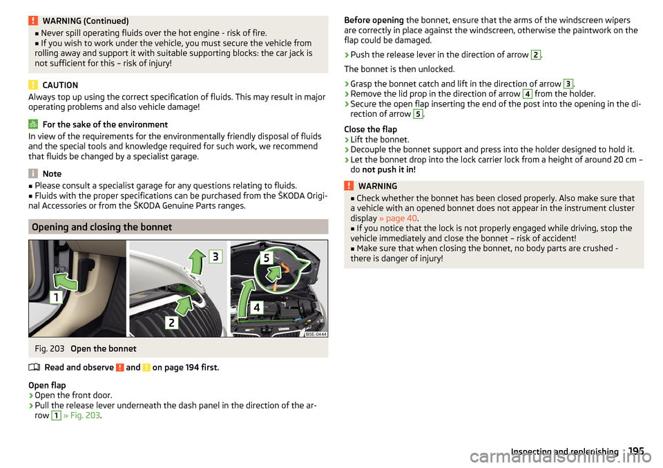
Fig. 203
Open the bonnet
Read and observe
and on page 194 first.
Open flap
›
Open the front door.
›
Pull the release lever underneath the dash panel in the direction of the ar-
row
1
» Fig. 203 .
Before opening the bonnet, ensure that the arms of the windscreen wipers
are correctly in place against the windscreen, otherwise the paintwork on the
flap could be damaged.›
Push the release lever in the direction of arrow
2
.
The bonnet is then unlocked.
›
Grasp the bonnet catch and lift in the direction of arrow
3
.
›
Remove the lid prop in the direction of arrow
4
from the holder.
›
Secure the open flap inserting the end of the post into the opening in the di-
rection of arrow
5
.
Close the flap
›
Lift the bonnet.
›
Decouple the bonnet support and press into the holder designed to hold it.
›
Let the bonnet drop into the lock carrier lock from a height of around 20 cm – do not push it in!
WARNING■
Check whether the bonnet has been closed properly. Also make sure that
a vehicle with an opened bonnet does not appear in the instrument cluster
display » page 40 .■
If you notice that the lock is not properly engaged while driving, stop the
vehicle immediately and close the bonnet – risk of accident!
■
Make sure that when closing the bonnet, no body parts are crushed -
there is danger of injury!
195Inspecting and replenishing
Page 198 of 268
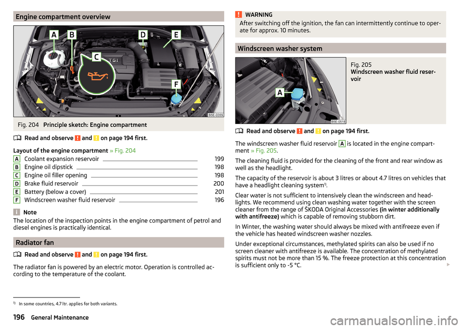
Engine compartment overviewFig. 204
Principle sketch: Engine compartment
Read and observe
and on page 194 first.
Layout of the engine compartment » Fig. 204
Coolant expansion reservoir
199
Engine oil dipstick
198
Engine oil filler opening
198
Brake fluid reservoir
200
Battery (below a cover)
201
Windscreen washer fluid reservoir
196
Note
The location of the inspection points in the engine compartment of petrol and
diesel engines is practically identical.
Radiator fan
Read and observe
and on page 194 first.
The radiator fan is powered by an electric motor. Operation is controlled ac-
cording to the temperature of the coolant.
ABCDEFWARNINGAfter switching off the ignition, the fan can intermittently continue to oper-
ate for approx. 10 minutes.
Windscreen washer system
Fig. 205
Windscreen washer fluid reser-
voir
Read and observe and on page 194 first.
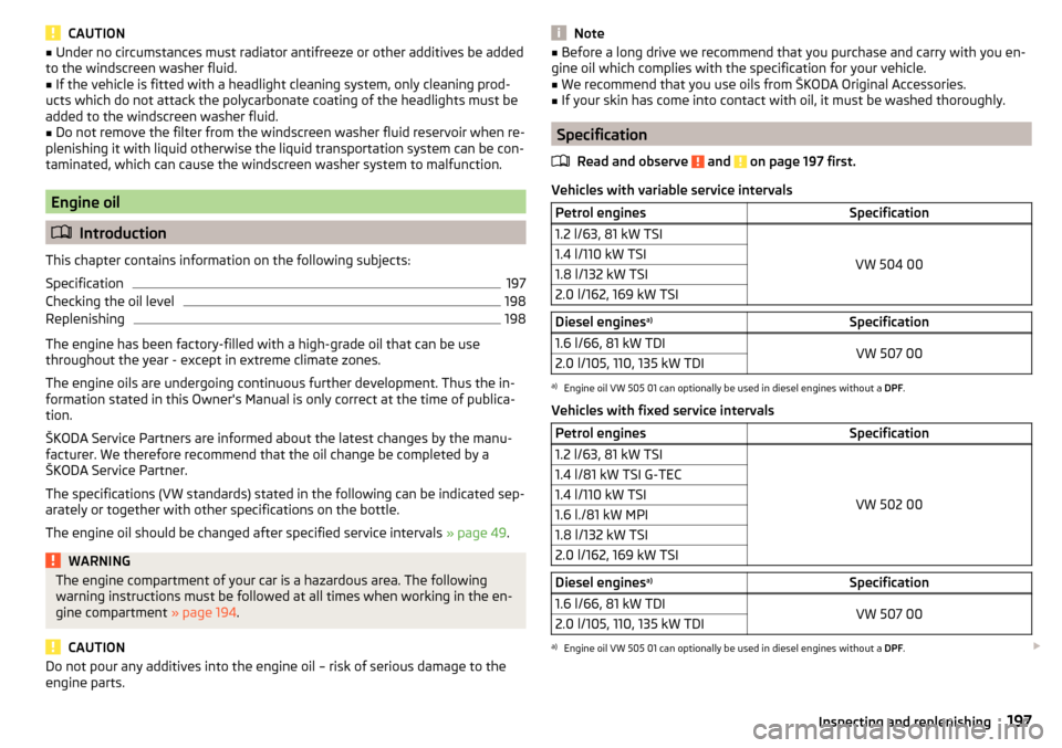
The windscreen washer fluid reservoir
A
is located in the engine compart-
ment » Fig. 205 .
The cleaning fluid is provided for the cleaning of the front and rear window as
well as the headlight.
The capacity of the reservoir is about 3 litres or about 4.7 litres on vehicles that
have a headlight cleaning system 1)
.
Clear water is not sufficient to intensively clean the windscreen and head-
lights. We recommend using clean washing water together with the screen
cleaner from the range of ŠKODA Original Accessories (in winter additionally
with antifreeze) which is capable of removing stubborn dirt.
In Winter, the washing water should always be mixed with antifreeze even if
the vehicle has heated windscreen washer nozzles.
Under exceptional circumstances, methylated spirits can also be used if no
screen cleaner with antifreeze is available. The concentration of methylated
spirits must not be more than 15 %. The freeze protection at this concentration
is sufficient only to -5 °C.
1)
In some countries, 4.7 ltr. applies for both variants.
196General Maintenance
Page 199 of 268
CAUTION■Under no circumstances must radiator antifreeze or other additives be added
to the windscreen washer fluid.■
If the vehicle is fitted with a headlight cleaning system, only cleaning prod-
ucts which do not attack the polycarbonate coating of the headlights must be
added to the windscreen washer fluid.
■
Do not remove the filter from the windscreen washer fluid reservoir when re-
plenishing it with liquid otherwise the liquid transportation system can be con-
taminated, which can cause the windscreen washer system to malfunction.
Engine oil
Introduction
This chapter contains information on the following subjects:
Specification
197
Checking the oil level
198
Replenishing
198
The engine has been factory-filled with a high-grade oil that can be use
throughout the year - except in extreme climate zones.
The engine oils are undergoing continuous further development. Thus the in- formation stated in this Owner's Manual is only correct at the time of publica-
tion.
ŠKODA Service Partners are informed about the latest changes by the manu-
facturer. We therefore recommend that the oil change be completed by a
ŠKODA Service Partner.
The specifications (VW standards) stated in the following can be indicated sep-
arately or together with other specifications on the bottle.
The engine oil should be changed after specified service intervals » page 49.
WARNINGThe engine compartment of your car is a hazardous area. The following
warning instructions must be followed at all times when working in the en-
gine compartment » page 194.
CAUTION
Do not pour any additives into the engine oil – risk of serious damage to the
engine parts.Note■ Before a long drive we recommend that you purchase and carry with you en-
gine oil which complies with the specification for your vehicle.■
We recommend that you use oils from ŠKODA Original Accessories.
■
If your skin has come into contact with oil, it must be washed thoroughly.
Specification
Read and observe
and on page 197 first.
Vehicles with variable service intervals
Petrol enginesSpecification1.2 l/63, 81 kW TSI
VW 504 00
1.4 l/110 kW TSI1.8 l/132 kW TSI2.0 l/162, 169 kW TSIDiesel engines a)Specification1.6 l/66, 81 kW TDIVW 507 002.0 l/105, 110, 135 kW TDIa)
Engine oil VW 505 01 can optionally be used in diesel engines without a
DPF.
Vehicles with fixed service intervals
Petrol enginesSpecification1.2 l/63, 81 kW TSI
VW 502 00
1.4 l/81 kW TSI G-TEC1.4 l/110 kW TSI1.6 l./81 kW MPI1.8 l/132 kW TSI2.0 l/162, 169 kW TSIDiesel engines a)Specification1.6 l/66, 81 kW TDIVW 507 002.0 l/105, 110, 135 kW TDIa)
Engine oil VW 505 01 can optionally be used in diesel engines without a
DPF.
197Inspecting and replenishing
Page 206 of 268
›Firstly disconnect the battery's negative terminal
, followed by the positive
terminal .
Connecting›
Firstly connect the battery's positive terminal
, followed by the negative
terminal
.
After disconnecting and re-connecting the vehicle battery, the following func- tions or devices are partially or completely inoperative.
Function / deviceOperating measureElectrical power windows» page 64Panorama sliding/tilting roof» page 66Sun screen» page 66Time settings» page 31
CAUTION
■ Disconnect the vehicle battery only with the ignition turned off - there is a
risk of damaging the electrical system of the vehicle.■
Under no circumstances must the battery cables be connected incorrectly –
risk of a cable fire.
Note
■ After disconnecting and re-connecting the vehicle battery, we recommend
having the vehicle checked by a specialist to ensure that the full functionality
of all electrical systems is guaranteed.■
The data of the multi-function display will be reset.
Automatic load deactivation
Read and observe
and on page 201 first.
The vehicle's electrical system automatically prevents the battery from dis-
charging when the battery is being heavily used. This manifests itself by the
following. ▶ The idling speed is raised to allow the generator to deliver more electricity to
the electrical system.
▶ Where appropriate large convenience consumers, e.g. seat heaters, rear win-
dow heaters, have their power limited or in case of emergency shut off com-
pletely.
CAUTION■ Despite such intervention by the vehicle electric system management, the
vehicle battery may be drained. For example, when the ignition is switched on
a long time with the engine turned off or the side or parking lights are turned
on during longer parking.■
Consumers which are supplied via a 12 V socket can cause the vehicle battery
to discharge when the ignition is switched off.
Note
Driving comfort is not disrupted by any shutting off of consumers. Often the
driver is not aware of it having taken place.204General Maintenance
Page 223 of 268
Vehicles with automatic transmission may be towed in with a tow bar or a tow
rope or with the front wheels raised. If the vehicle is raised at rear, the auto-
matic gearbox is damaged! If possible, the vehicle should be towed with the
engine running or at least with the ignition on.
Driver of the tow vehicle›
Engage the clutch gently when starting off or depress the accelerator partic-
ularly gently if the vehicle is fitted with an automatic gearbox.
›
Only then approach correctly when the rope is taut.
The maximum towing speed is 50 km/h.
Driver of the towed vehicle
›
Switch on the ignition so that the steering wheel is not locked and so that
the turn signal lights, windscreen wipers and windscreen washer system can
be used.
›
Take the vehicle out of gear or move the selector lever into position N if the
vehicle is fitted with an automatic gearbox.
Please note that the brake servo unit and power steering only operate if the
engine is running. If the engine is not running, significantly more physical force
is required to depress the brake pedal and steer the vehicle.
If using a tow rope, ensure that it is always kept taught.
General information for the towing process
Both drivers should be familiar with the problems which might possibly occur while a vehicle is being towed. Unskilled drivers should not attempt to tow in
another vehicle or to be towed in.
The vehicle must be transported on a special breakdown vehicle or trailer if it
is not possible to tow in the vehicle in the way described or if the towing dis-
tance is greater than 50 km.
If the gearbox no longer contains any oil, your vehicle must only be towed with
the front axle raised clear of the ground or on a breakdown vehicle or trailer.
To protect both vehicles when tow-starting or towing, the tow rope should be
elastic. Thus one should only use plastic fibre rope or a rope made out of a
similarly elastic material.
Attach the tow rope or the tow bar to the towing eyes » page 221 or
» page 222 to the detachable ball head of the towing equipment » page 167 .
WARNING■
When towing, exercise increased caution.■Spiral tow ropes must not be used for towing » Fig. 226- , the towing
eye may unscrew out of the vehicle - risk of accident.■
The tow rope should not be twisted - risk of accident.
CAUTION
■ Do not start engine by towing - there is a risk of damaging the engine parts.
The battery from another vehicle can be used as a jump-start aid » page 219,
Jump-starting .■
There is always a risk of excessive stresses and damage resulting at the
points to which you attach the tow rope or tow bar when you attempt to tow a
vehicle which is not standing on a paved road.
Note
We recommend using a tow rope from ŠKODA Original Accessories available
from a ŠKODA Partner.
Front towing eye
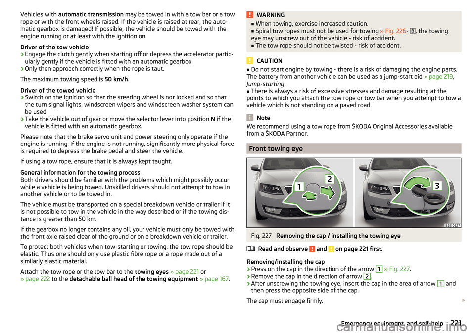
Fig. 227
Removing the cap / installing the towing eye
Read and observe
and on page 221 first.
Removing/installing the cap
›
Press on the cap in the direction of the arrow
1
» Fig. 227 .
›
Remove the cap in the direction of arrow
2
.
›
After unscrewing the towing eye, insert the cap in the area of arrow
1
and
then press the opposite side of the cap.
The cap must engage firmly.
221Emergency equipment, and self-help
Page 227 of 268
›Open the boot lid.
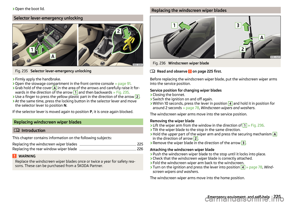
Selector lever-emergency unlocking
Fig. 235
Selector lever-emergency unlocking
›
Firmly apply the handbrake.
›
Open the stowage compartment in the front centre console
» page 91.
›
Grab hold of the cover
A
in the area of the arrows and carefully raise it for-
wards in the direction of the arrow
1
and then backwards » Fig. 235.
›
Use a finger to press the yellow plastic part in the direction of the arrow
2
.
›
At the same time, press the locking button in the selector lever and move
the selector lever to position N.
If the selector lever is moved again to position P, it is once again blocked.
Replacing windscreen wiper blades
Introduction
This chapter contains information on the following subjects:
Replacing the windscreen wiper blades
225
Replacing the rear window wiper blade
226WARNINGReplace the windscreen wiper blades once or twice a year for safety rea-
sons. These can be purchased from a ŠKODA Partner.Replacing the windscreen wiper bladesFig. 236
Windscreen wiper blade
Read and observe
on page 225 first.
Before replacing the windscreen wiper blade, put the windscreen wiper arms
into the service position.
Service position for changing wiper blades
›
Closing the bonnet.
›
Switch the ignition on and off again.
›
Within 10 seconds, press the lever in position
4
and hold it in position for
around 2 seconds » page 78, Windscreen wipers and washers .
The windscreen wiper arms move into the service position.
Removing the wiper blade
›
Lift the wiper arm from the window in the direction of
1
» Fig. 236 .
›
Tilt the wiper blade to the stop in the same direction.
›
Hold the upper part of the wiper arm and press the securing mechanism
A
in the direction of arrow
2
.
›
Remove the wiper blade in the direction of the arrow
3
.
Attaching the windscreen wiper blade
›
Push the windscreen wiper blade to the stop until it locks into place.
›
Check that the windscreen wiper blade is correctly attached.
›
Fold the windscreen wiper arm back to the windscreen.
›
Turn on the ignition and press the lever into position
4
» page 78 , Wind-
screen wipers and washers .
The windscreen wiper arms move into the home position.
225Emergency equipment, and self-help
Page 228 of 268
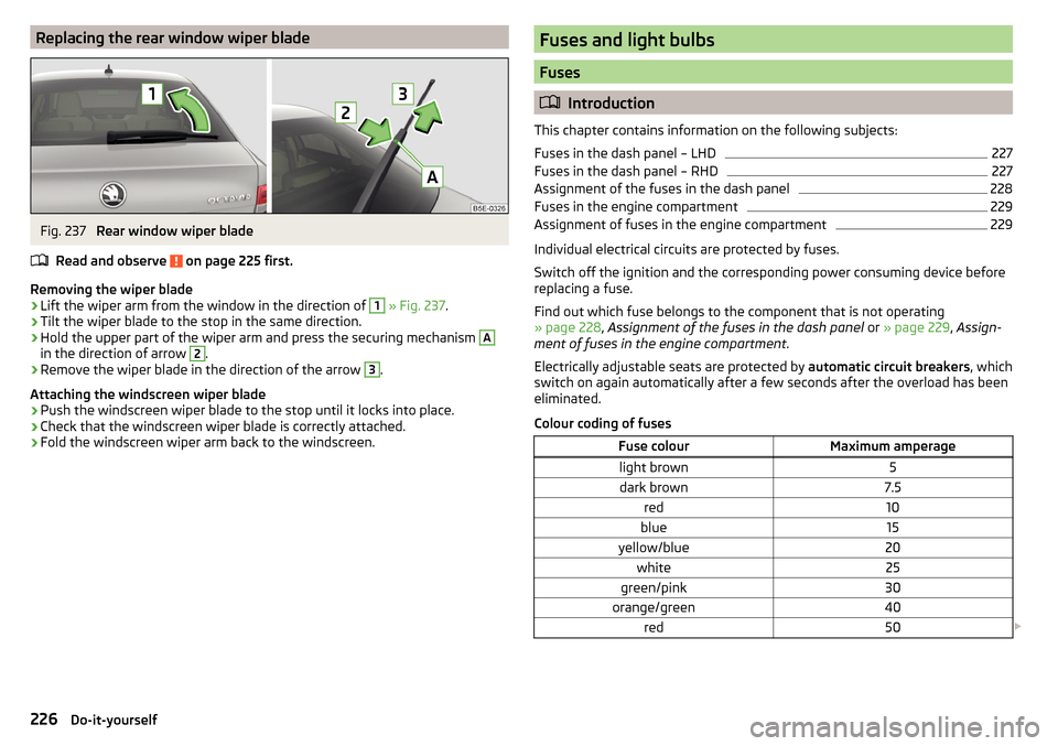
Replacing the rear window wiper bladeFig. 237
Rear window wiper blade
Read and observe
on page 225 first.
Removing the wiper blade
›
Lift the wiper arm from the window in the direction of
1
» Fig. 237 .
›
Tilt the wiper blade to the stop in the same direction.
›
Hold the upper part of the wiper arm and press the securing mechanism
A
in the direction of arrow
2
.
›
Remove the wiper blade in the direction of the arrow
3
.
Attaching the windscreen wiper blade
›
Push the windscreen wiper blade to the stop until it locks into place.
›
Check that the windscreen wiper blade is correctly attached.
›
Fold the windscreen wiper arm back to the windscreen.
Fuses and light bulbs
Fuses
Introduction
This chapter contains information on the following subjects:
Fuses in the dash panel – LHD
227
Fuses in the dash panel – RHD
227
Assignment of the fuses in the dash panel
228
Fuses in the engine compartment
229
Assignment of fuses in the engine compartment
229
Individual electrical circuits are protected by fuses.
Switch off the ignition and the corresponding power consuming device before
replacing a fuse.
Find out which fuse belongs to the component that is not operating
» page 228 , Assignment of the fuses in the dash panel or » page 229 , Assign-
ment of fuses in the engine compartment .
Electrically adjustable seats are protected by automatic circuit breakers, which
switch on again automatically after a few seconds after the overload has been
eliminated.
Colour coding of fuses
Fuse colourMaximum amperagelight brown5dark brown7.5red10blue15yellow/blue20white25green/pink30orange/green40red50 226Do-it-yourself