key SKODA OCTAVIA 2015 3.G / (5E) Repair Manual
[x] Cancel search | Manufacturer: SKODA, Model Year: 2015, Model line: OCTAVIA, Model: SKODA OCTAVIA 2015 3.G / (5E)Pages: 268, PDF Size: 37.54 MB
Page 211 of 268
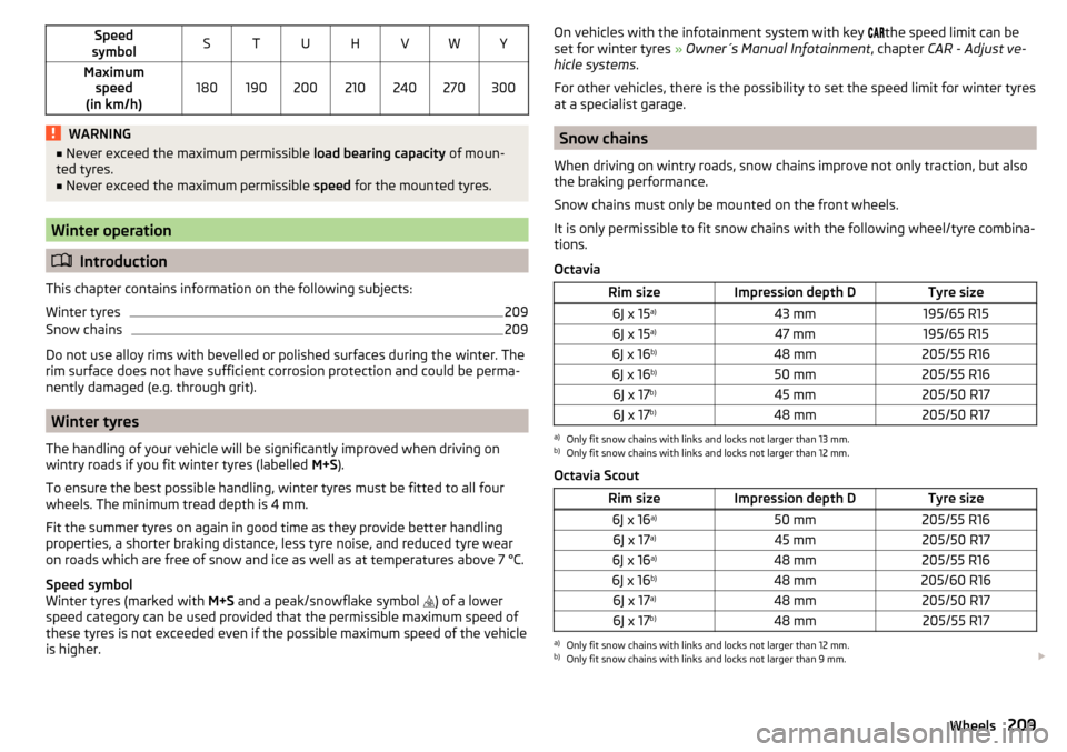
Speed
symbolSTUHVWYMaximum speed
(in km/h)180190200210240270300WARNING■ Never exceed the maximum permissible load bearing capacity of moun-
ted tyres.■
Never exceed the maximum permissible speed for the mounted tyres.
Winter operation
Introduction
This chapter contains information on the following subjects:
Winter tyres
209
Snow chains
209
Do not use alloy rims with bevelled or polished surfaces during the winter. The
rim surface does not have sufficient corrosion protection and could be perma-
nently damaged (e.g. through grit).
Winter tyres
The handling of your vehicle will be significantly improved when driving on
wintry roads if you fit winter tyres (labelled M+S).
To ensure the best possible handling, winter tyres must be fitted to all four
wheels. The minimum tread depth is 4 mm.
Fit the summer tyres on again in good time as they provide better handling
properties, a shorter braking distance, less tyre noise, and reduced tyre wear
on roads which are free of snow and ice as well as at temperatures above 7 °C.
Speed symbol
Winter tyres (marked with M+S and a peak/snowflake symbol
) of a lower
speed category can be used provided that the permissible maximum speed of
these tyres is not exceeded even if the possible maximum speed of the vehicle
is higher.
On vehicles with the infotainment system with key the speed limit can be
set for winter tyres » Owner´s Manual Infotainment , chapter CAR - Adjust ve-
hicle systems .
For other vehicles, there is the possibility to set the speed limit for winter tyres
at a specialist garage.
Snow chains
When driving on wintry roads, snow chains improve not only traction, but also
the braking performance.
Snow chains must only be mounted on the front wheels.
It is only permissible to fit snow chains with the following wheel/tyre combina-
tions.
Octavia
Rim sizeImpression depth DTyre size6J x 15 a)43 mm195/65 R156J x 15a)47 mm195/65 R156J x 16 b)48 mm205/55 R166J x 16b)50 mm205/55 R166J x 17b)45 mm205/50 R176J x 17 b)48 mm205/50 R17a)
Only fit snow chains with links and locks not larger than 13 mm.
b)
Only fit snow chains with links and locks not larger than 12 mm.
Octavia Scout
Rim sizeImpression depth DTyre size6J x 16 a)50 mm205/55 R166J x 17a)45 mm205/50 R176J x 16 a)48 mm205/55 R166J x 16 b)48 mm205/60 R166J x 17a)48 mm205/50 R176J x 17b)48 mm205/55 R17a)
Only fit snow chains with links and locks not larger than 12 mm.
b)
Only fit snow chains with links and locks not larger than 9 mm.
209Wheels
Page 214 of 268
Fire extinguisherFig. 215
Fire extinguisher
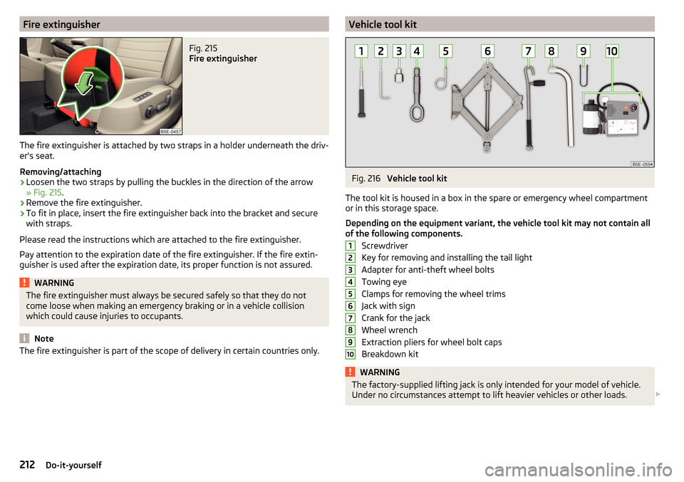
The fire extinguisher is attached by two straps in a holder underneath the driv-
er's seat.
Removing/attaching
›
Loosen the two straps by pulling the buckles in the direction of the arrow
» Fig. 215 .
›
Remove the fire extinguisher.
›
To fit in place, insert the fire extinguisher back into the bracket and secure
with straps.
Please read the instructions which are attached to the fire extinguisher.
Pay attention to the expiration date of the fire extinguisher. If the fire extin- guisher is used after the expiration date, its proper function is not assured.
WARNINGThe fire extinguisher must always be secured safely so that they do not
come loose when making an emergency braking or in a vehicle collision
which could cause injuries to occupants.
Note
The fire extinguisher is part of the scope of delivery in certain countries only.Vehicle tool kitFig. 216
Vehicle tool kit
The tool kit is housed in a box in the spare or emergency wheel compartment
or in this storage space.
Depending on the equipment variant, the vehicle tool kit may not contain all
of the following components.
Screwdriver
Key for removing and installing the tail light
Adapter for anti-theft wheel bolts
Towing eye
Clamps for removing the wheel trims
Jack with sign
Crank for the jack
Wheel wrench
Extraction pliers for wheel bolt caps
Breakdown kit
WARNINGThe factory-supplied lifting jack is only intended for your model of vehicle.
Under no circumstances attempt to lift heavier vehicles or other loads. 12345678910212Do-it-yourself
Page 225 of 268
Remote control
Introduction
This chapter contains information on the following subjects:
Replacing the battery in the remote control key
223
Synchronising the remote control
223
replace battery in the remote control the auxiliary heating (auxiliary
heating)
223
CAUTION
■ We recommend having faulty rechargeable batteries replaced by a ŠKODA
service partner.■
Pay attention to the correct polarity when changing the battery.
Note
If a key has an affixed decorative cover, this will be destroyed when the bat-
tery is replaced. A replacement cover can be purchased from a ŠKODA Partner.
Replacing the battery in the remote control key
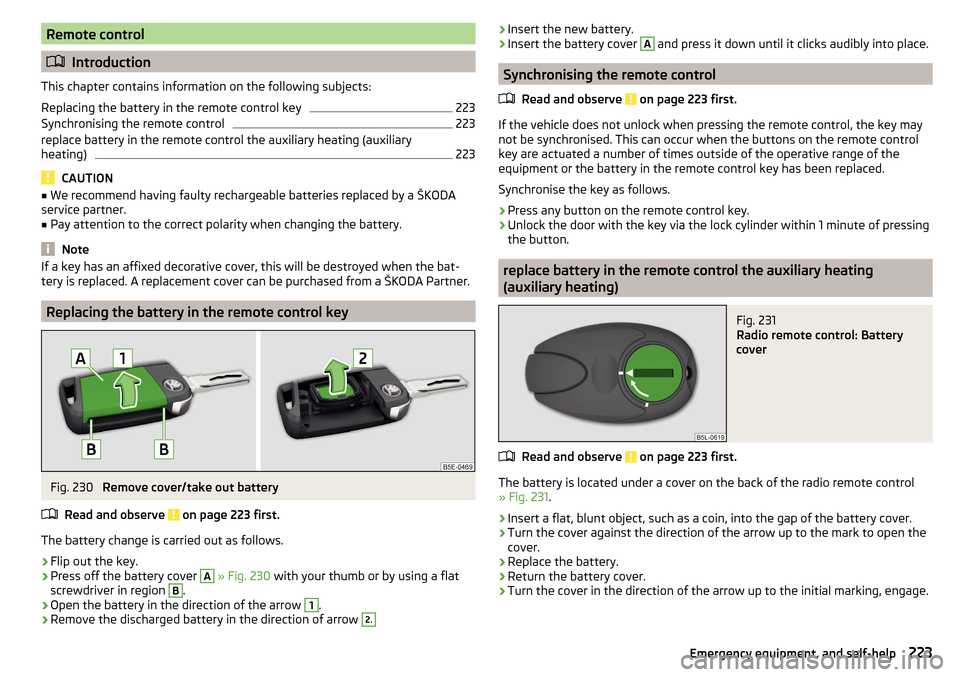
Fig. 230
Remove cover/take out battery
Read and observe
on page 223 first.
The battery change is carried out as follows.
›
Flip out the key.
›
Press off the battery cover
A
» Fig. 230 with your thumb or by using a flat
screwdriver in region
B
.
›
Open the battery in the direction of the arrow
1
.
›
Remove the discharged battery in the direction of arrow
2.› Insert the new battery.›Insert the battery cover A and press it down until it clicks audibly into place.
Synchronising the remote control
Read and observe
on page 223 first.
If the vehicle does not unlock when pressing the remote control, the key may
not be synchronised. This can occur when the buttons on the remote control
key are actuated a number of times outside of the operative range of the
equipment or the battery in the remote control key has been replaced.
Synchronise the key as follows.
›
Press any button on the remote control key.
›
Unlock the door with the key via the lock cylinder within 1 minute of pressing
the button.
replace battery in the remote control the auxiliary heating
(auxiliary heating)
Fig. 231
Radio remote control: Battery
cover
Read and observe on page 223 first.
The battery is located under a cover on the back of the radio remote control
» Fig. 231 .
›
Insert a flat, blunt object, such as a coin, into the gap of the battery cover.
›
Turn the cover against the direction of the arrow up to the mark to open the
cover.
›
Replace the battery.
›
Return the battery cover.
›
Turn the cover in the direction of the arrow up to the initial marking, engage.
223Emergency equipment, and self-help
Page 226 of 268
Emergency unlocking/locking
Introduction
This chapter contains information on the following subjects:
Unlocking/locking the driver's door
224
Locking the door without a locking cylinder
224
Unlock the boot lid
224
Selector lever-emergency unlocking
225
Unlocking/locking the driver's door
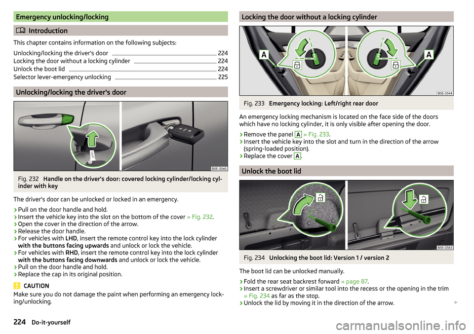
Fig. 232
Handle on the driver's door: covered locking cylinder/locking cyl-
inder with key
The driver's door can be unlocked or locked in an emergency.
›
Pull on the door handle and hold.
›
Insert the vehicle key into the slot on the bottom of the cover » Fig. 232.
›
Open the cover in the direction of the arrow.
›
Release the door handle.
›
For vehicles with LHD, insert the remote control key into the lock cylinder
with the buttons facing upwards and unlock or lock the vehicle.
›
For vehicles with RHD, insert the remote control key into the lock cylinder
with the buttons facing downwards and unlock or lock the vehicle.
›
Pull on the door handle and hold.
›
Replace the cap in its original position.
CAUTION
Make sure you do not damage the paint when performing an emergency lock-
ing/unlocking.Locking the door without a locking cylinderFig. 233
Emergency locking: Left/right rear door
An emergency locking mechanism is located on the face side of the doors
which have no locking cylinder, it is only visible after opening the door.
›
Remove the panel
A
» Fig. 233 .
›
Insert the vehicle key into the slot and turn in the direction of the arrow
(spring-loaded position).
›
Replace the cover
A
.
Unlock the boot lid
Fig. 234
Unlocking the boot lid: Version 1 / version 2
The boot lid can be unlocked manually.
›
Fold the rear seat backrest forward » page 87.
›
Insert a screwdriver or similar tool into the recess or the opening in the trim
» Fig. 234 as far as the stop.
›
Unlock the lid by moving it in the direction of the arrow.
224Do-it-yourself
Page 234 of 268
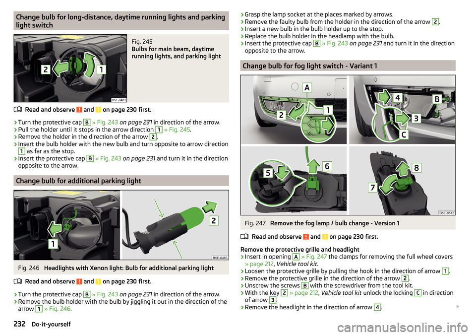
Change bulb for long-distance, daytime running lights and parking
light switchFig. 245
Bulbs for main beam, daytime
running lights, and parking light
Read and observe and on page 230 first.
›
Turn the protective cap
B
» Fig. 243 on page 231 in direction of the arrow.
›
Pull the holder until it stops in the arrow direction
1
» Fig. 245 .
›
Remove the holder in the direction of the arrow
2
.
›
Insert the bulb holder with the new bulb and turn opposite to arrow direction
1
as far as the stop.
›
Insert the protective cap
B
» Fig. 243 on page 231 and turn it in the direction
opposite to the arrow.
Change bulb for additional parking light
Fig. 246
Headlights with Xenon light: Bulb for additional parking light
Read and observe
and on page 230 first.
›
Turn the protective cap
B
» Fig. 243 on page 231 in direction of the arrow.
›
Remove the bulb holder with the bulb by jiggling it out in the direction of the
arrow
1
» Fig. 246 .
›Grasp the lamp socket at the places marked by arrows.›Remove the faulty bulb from the holder in the direction of the arrow 2.›
Insert a new bulb in the bulb holder up to the stop.
›
Replace the bulb holder in the headlamp with the bulb.
›
Insert the protective cap
B
» Fig. 243 on page 231 and turn it in the direction
opposite to the arrow.
Change bulb for fog light switch - Variant 1
Fig. 247
Remove the fog lamp / bulb change - Version 1
Read and observe
and on page 230 first.
Remove the protective grille and headlight
›
Insert in opening
A
» Fig. 247 the clamps for removing the full wheel covers
» page 212 , Vehicle tool kit .
›
Loosen the protective grille by pulling the hook in the direction of arrow
1
.
›
Remove the protective grille in the direction of the arrow
2
.
›
Unscrew the screws
B
with the screwdriver from the tool kit.
›
With the key
2
» page 212 , Vehicle tool kit unlock the locking
C
in direction
of arrow
3
.
›
Remove the headlight in the direction of arrow
4
.
232Do-it-yourself
Page 235 of 268
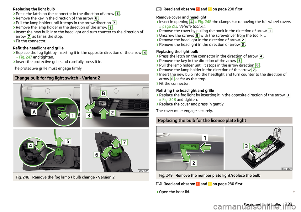
Replacing the light bulb›Press the latch on the connector in the direction of arrow 5.›
Remove the key in the direction of the arrow
6
.
›
Pull the lamp holder until it stops in the arrow direction
7
.
›
Remove the lamp holder in the direction of the arrow
8
.
›
Insert the new bulb into the headlight and turn counter to the direction of
arrow
7
as far as the stop.
›
Fit the connector.
Refit the headlight and grille
›
Replace the fog light by inserting it in the opposite direction of the arrow
4
» Fig. 247 and tighten.
›
Insert the protective grille and carefully press it in.
The protective grille must engage firmly.
Change bulb for fog light switch - Variant 2
Fig. 248
Remove the fog lamp / bulb change - Version 2
Read and observe and on page 230 first.
Remove cover and headlight
›
Insert in opening
A
» Fig. 248 the clamps for removing the full wheel covers
» page 212 , Vehicle tool kit .
›
Remove the cover by pulling the hook in the direction of arrow
1
.
›
Unscrew the screws
B
with the screwdriver from the tool kit.
›
Remove the headlight in the direction of arrow
2
.
›
Remove the headlight in the direction of arrow
3
.
Replacing the light bulb
›
Press the latch on the connector in the direction of arrow
4
.
›
Remove the key in the direction of the arrow
5
.
›
Pull the lamp holder until it stops in the arrow direction
6
.
›
Remove the lamp holder in the direction of the arrow
7
.
›
Insert the new bulb into the headlight and turn counter to the direction of
arrow
6
as far as the stop.
›
Fit the connector.
Refitting the headlight and grille
›
Replace the fog light by inserting it in the opposite direction of the arrow
3
» Fig. 248 and tighten.
›
Replace the cover and press in gently.
The cover must engage securely.
Replacing the bulb for the licence plate light
Fig. 249
Remove the number plate light/replace the bulb
Read and observe
and on page 230 first.
›
Open the boot lid.
233Fuses and light bulbs
Page 236 of 268
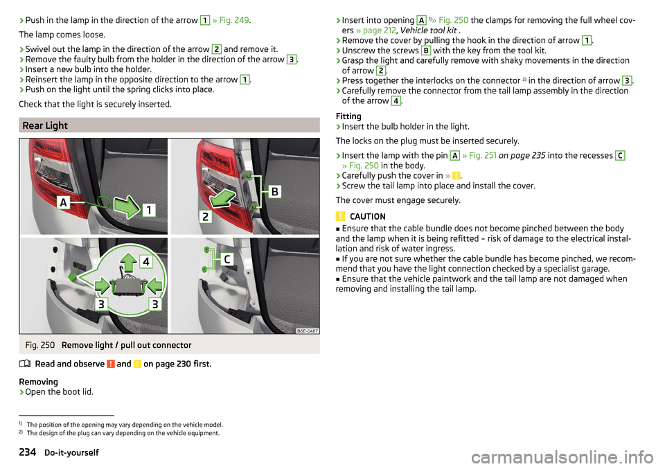
›Push in the lamp in the direction of the arrow 1
» Fig. 249 .
The lamp comes loose.›
Swivel out the lamp in the direction of the arrow
2
and remove it.
›
Remove the faulty bulb from the holder in the direction of the arrow
3
.
›
Insert a new bulb into the holder.
›
Reinsert the lamp in the opposite direction to the arrow
1
.
›
Push on the light until the spring clicks into place.
Check that the light is securely inserted.
Rear Light
Fig. 250
Remove light / pull out connector
Read and observe
and on page 230 first.
Removing
›
Open the boot lid.
› Insert into opening A 1)
» Fig. 250 the clamps for removing the full wheel cov-
ers » page 212 , Vehicle tool kit .›
Remove the cover by pulling the hook in the direction of arrow
1
.
›
Unscrew the screws
B
with the key from the tool kit.
›
Grasp the light and carefully remove with shaky movements in the direction
of arrow
2
.
›
Press together the interlocks on the connector 2)
in the direction of arrow
3
.
›
Carefully remove the connector from the tail lamp assembly in the direction
of the arrow
4
.
Fitting
›
Insert the bulb holder in the light.
The locks on the plug must be inserted securely.
›
Insert the lamp with the pin
A
» Fig. 251 on page 235 into the recesses
C
» Fig. 250 in the body.
›
Carefully push the cover in » .
›
Screw the tail lamp into place and install the cover.
The cover must engage securely.
CAUTION
■ Ensure that the cable bundle does not become pinched between the body
and the lamp when it is being refitted – risk of damage to the electrical instal-
lation and risk of water ingress.■
If you are not sure whether the cable bundle has become pinched, we recom-
mend that you have the light connection checked by a specialist garage.
■
Ensure that the vehicle paintwork and the tail lamp are not damaged when
removing and installing the tail lamp.
1)
The position of the opening may vary depending on the vehicle model.
2)
The design of the plug can vary depending on the vehicle equipment.
234Do-it-yourself
Page 252 of 268
Avoiding damage to your vehicle134
B
Bags on the backs of the front seats
96
Ball head Check fitting
170
Ready position168
Ball rod Ready position
168
Battery In the remote control key
223
Belts11
Belt tensioners13
Bonnet Closing
195
Opening195
Boot Class N1 vehicles
107
See Boot lid59
Boot lid automatic locking
59
Closing59
Opening59
Brake information messages
32
warning light32
Brake Assist (HBA)137
Brake booster127
brake fluid specification
201
Brake fluid200
Checking200
information messages32
Brake linings warning light
36
Brake pedal (automatic transmission) Warning light
37
Brakes Brake booster127
Brake fluid200
Braking and stabilisation systems135
Handbrake127
Running-in132
Brakes and parking126
Brake system135
Braking Information on braking
126
Bulbs Replacing
230
Buttons in the doors electric window lifters
62
C
Camera Lens care
185
Camera lens care
185
Car computer see multifunction display
41
Care and maintenance178
Cargo element106
Caring for the vehicle exterior Towing hitch
186
Car park128
Car park ticket holder90
Carrier Roof rack
110
Cavity protection185
Central locking53
Problems57
Central locking button55
Change bulb for additional parking light
232
bulb for fog lights - Version 1232
bulb for fog lights - Version 2233
bulb for high beam232
bulb for the parking light232
bulb in the rear light - Version 1235
bulb in the rear light - Version 2235
daytime running light bulb232
light bulb in tail light234
Changing Engine oil
197
Wheels213
Changing a wheel Follow-up tasks
216
Preparation213
Changing wheels Wheel removal and fix
216
Charging a vehicle battery203
Check Fit ball head properly
170
Checking Battery electrolyte level
202
Brake fluid200
Coolant199
Engine oil198
Oil level198
Windscreen washer fluid196
Checks Statutory checks
178
Children and safety20
Child safety Side airbag
22
Child safety lock57
Child safety seat Use of child safety seats
22
Child seat Classification
22
ISOFIX23
on the front passenger seat21
TOP TETHER25
Use of ISOFIX child seats24
Chrome parts Refer to vehicle maintenance
184
Cigarette lighter92
250Index
Page 256 of 268
Temperature gauge29
Warning lights31
Interior care186
Natural leather187
Interior light Front
74
Interior lights Rear
75
Interior monitor58
iPad holder Behind the headrests
99
Handling99
ISOFIX23
J
Jack
212
Maintenance185
Jump-starting219
K
KESSY Locking
55
Unlocking55
Key Locking
54
Starting the engine121
Stopping the engine121
Switching off the ignition121
Switching on the ignition121
Unlocking54
Key CAR see Infotainment
4
Knee airbag17
L
Lamp failure Warning light
38
Lamps Warning light
38
Lane Assistsee Lane Departure Warning160
Warning light36
Lane Departure Warning160
Activation / deactivation162
Information messages162
Operation161
Lap timer48
Leather Natural leather care
187
LEAVING HOME73
Lever Main beam
69
Turn signal69
Levers Windscreen wipers
78
Light Cockpit
74
COMING HOME / LEAVING HOME73
Fog lights72
Headlights with CORNER function73
High-beam assistant71
Rear fog light72
Replacing bulbs230
travel mode71
Xenon headlight70
Light Assist High-beam assistant
71
lighting entry space
75
Lighting Luggage compartment
100
Lights67
Automatic driving lamp control70
Daylight running68
Hazard warning light system73
Headlight beam range regulation68
Headlight flasher69
Low beam68
Main beam69
Parking lights68, 74
Switching on and off68
Turn signal69
Warning lights31
Load238
Locking Individual settings
56
KESSY55
Key54
Remote control54
Locking and unlocking the vehicle from the in- side
55
Locking the door without a locking cylinder Emergency
224
Long cargo channel88
Low beam68
Low tyre pressure warning See tyre pressure monitoring
165
Luggage compartment100
Compartment with cargo element106
Cover104
Fastening elements101
Fix floor covering103
Fixing nets102
floor covering on both sides103
foldable hook103
Folding double hooks103
Lighting100
Luggage net104
Net partition109
Roll-up cover105
Storage compartments under the floor cover- ing
106
Stowing the roof rack111
unlock manually224
Unlock the boot lid224
Variable loading floor107
Luggage compartment cover104
Roll-up cover105
254Index
Page 258 of 268
P
Park assist Departing from a parallel parking space
147
Information messages147
Parking146
Park Assist144
Automatic brake assist147
Operation145
Parking space search146
Parking128
Park Assist144
Parking aid140
Rear View Camera143
Parking aid140
Automatic system activation when moving for- ward
143
Function141
Parking assistance Activation / deactivation
142
Display in the Infotainment display142
Parking lights68
Park Pilot140
Park the vehicle see Parking
128
Part replacement178
Passive safety Before setting off
8
Driving safety8
Passive Safety8
Pedals128
Footmats128
Petrol see fuel
190
Phonebox91
Plastic parts184
Polishing vehicle paint work see vehicle care
183
Positioning the jack
215
Power limitsliding/tilting roof65
Power outlet 12 V
93
Power steering Warning light
33
Power windows61
Button in the front passenger door63
Button in the rear doors63
Practical equipment Reflective vest
211
Practical features 12-Volt power outlet
93
Pockets on the backs of the front seats96
Seat backrest with long cargo channel88
Waste container93
Proactive passenger protection160
Warning light35
ProActive passenger protection Function
160
Protective films183
Puncture repair kit217
R
Radiator fan
196
Radio see Infotainment
4
Radio remote control Auxiliary heating (heating and ventilation)
119
Raising the vehicle215
Rear-view mirror Exterior mirrors
80
Fold in passenger mirror80
Synchronous adjustment of the rear-view mir- ror
80
Rear fog light72
Warning light34
Rear mirror79
Rear View Camera143
Function keys144
Operation143
Orientation Lines144
Rear view mirror Interior mirror
79
Rear window - heater76
Refuelling189
Fuel189
Fuel - natural gas192
Remote control Locking
54
Replacing the battery223
Synchronisation process223
Unlocking54
Remote control key Replacing the battery
223
Removable through-loading bag98
Removing the bar ball, Step 1
170
bar ball, Step 2171
Repairs and technical alterations178
Replace the battery in the auxiliary heating (auxiliary heating) in the remote control
223
Replacing Bulb for the licence plate light
233
Bulbs230
Fuses226
Fuses – engine compartment229
Fuses – LHD227
Fuses – RHD227
Low beam bulb231
Rear window wiper blade226
Vehicle battery203
windscreen wiper blades225
Replenishing Coolant
200
Engine oil198
Windscreen washer fluid196
256Index