tow bar SKODA OCTAVIA 2015 3.G / (5E) Owner's Manual
[x] Cancel search | Manufacturer: SKODA, Model Year: 2015, Model line: OCTAVIA, Model: SKODA OCTAVIA 2015 3.G / (5E)Pages: 268, PDF Size: 37.54 MB
Page 107 of 268

CAUTION■When closing the boot lid, jamming and damage to the cover or the side trim
panel can occur if handled incorrectly. The following guidelines must be ob-
served. ■ The recesses in the cover B
» Fig. 118 must lock in the holders in the side
trim panel
C
.
■ The items which are transported must not exceed the height of the cover.
■ The cover must not be jammed in the surrounding seal of the luggage com-
partment lid when it is in the raised position. ■ There must be no object in the gap between the cover in the raise position
and the rear backrest.
Roll-up cover
Fig. 120
Roll-up cover: pull out/roll/remove
Fig. 121
Remove the side panels of the luggage compartment/stow the
roll-up luggage compartment cover
Read and observe and on page 101 first.
Extending
›
Grasp the cover on the handle
A
and pull it out in the direction of the arrow
1
until it clicks » Fig. 120.
Retracting
›
Push the cover in the area of handle
A
in the direction of the arrow
2
» Fig. 120 .
The cover rolls up automatically.
Removing/inserting
The fully rolled luggage compartment cover can be removed.
›
Press on the side of the cross bar in the direction of arrow
3
and remove
the cover in the arrow direction
4
» Fig. 120 .
Insertion takes place in reverse order.
Stowage
If the vehicle is equipped with the variable loading floor, then the removable
roll-up luggage compartment cover can be stowed in the recesses of the lug-
gage compartment side trim.
›
Fold the variable loading floor into the upper position » page 108.
›
Remove the side covers of the luggage compartment in the direction of the
arrow
1
» Fig. 121 .
›
Remove the roll-up luggage compartment cover » Fig. 120.
›
Insert the front part of the roll-up luggage compartment cover under a por-
tion of the side trim
D
» Fig. 121 on the left.
›
Fold the rear part of the roll-up luggage compartment cover in the direction
of arrow
2
» .
›
Replace the side trims of the luggage compartment in the opposite direction
of the arrow
1
.
›
Fold out the variable loading floor to the upper position » page 108.
WARNINGNo objects should be placed on the foldable boot cover. This could endan-
ger the vehicle occupants during sudden braking or vehicle impact.
CAUTION
If you want to stow the roll-up luggage compartment cover and the roof rack
at the same time , then it is necessary that the rear part of the roll-up luggage
compartment is covering the rear roof rack.105Transporting and practical equipment
Page 110 of 268
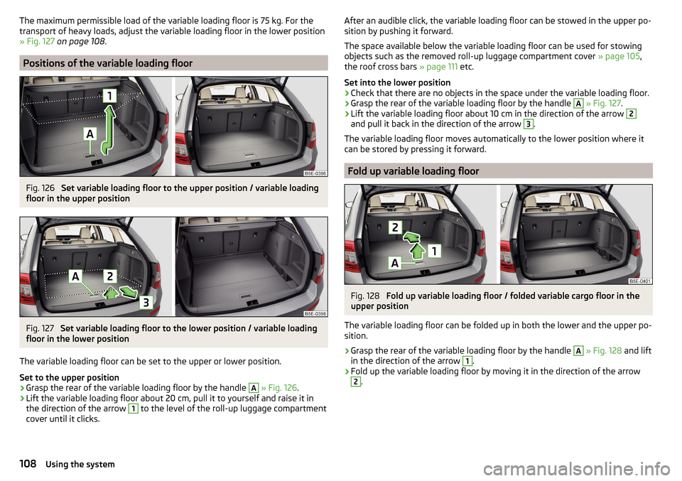
The maximum permissible load of the variable loading floor is 75 kg. For the
transport of heavy loads, adjust the variable loading floor in the lower position
» Fig. 127 on page 108 .
Positions of the variable loading floor
Fig. 126
Set variable loading floor to the upper position / variable loading
floor in the upper position
Fig. 127
Set variable loading floor to the lower position / variable loading
floor in the lower position
The variable loading floor can be set to the upper or lower position.
Set to the upper position
›
Grasp the rear of the variable loading floor by the handle
A
» Fig. 126 .
›
Lift the variable loading floor about 20 cm, pull it to yourself and raise it in
the direction of the arrow
1
to the level of the roll-up luggage compartment
cover until it clicks.
After an audible click, the variable loading floor can be stowed in the upper po-
sition by pushing it forward.
The space available below the variable loading floor can be used for stowing
objects such as the removed roll-up luggage compartment cover » page 105,
the roof cross bars » page 111 etc.
Set into the lower position›
Check that there are no objects in the space under the variable loading floor.
›
Grasp the rear of the variable loading floor by the handle
A
» Fig. 127 .
›
Lift the variable loading floor about 10 cm in the direction of the arrow
2
and pull it back in the direction of the arrow
3
.
The variable loading floor moves automatically to the lower position where it
can be stored by pressing it forward.
Fold up variable loading floor
Fig. 128
Fold up variable loading floor / folded variable cargo floor in the
upper position
The variable loading floor can be folded up in both the lower and the upper po-
sition.
›
Grasp the rear of the variable loading floor by the handle
A
» Fig. 128 and lift
in the direction of the arrow
1
.
›
Fold up the variable loading floor by moving it in the direction of the arrow
2
.
108Using the system
Page 112 of 268
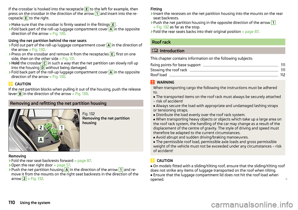
If the crossbar is hooked into the receptacle E to the left for example, then
press on the crossbar in the direction of the arrow 1 and insert into the re-
ceptacle E
to the right.
›
Make sure that the crossbar is firmly seated in the fittings
E
.
›
Fold back part of the roll-up luggage compartment cover
A
in the opposite
direction of the arrow » Fig. 130.
Using the net partition behind the rear seats
›
Fold out part of the roll-up luggage compartment cover
A
in the direction of
the arrow » Fig. 130.
›
Press on the crossbar and remove it from the receptacles
E
, first on one
side, then on the other side » Fig. 131.
›
Hold the crossbar
C
in such a way that the net partition can slowly roll up
into the housing
D
without being damaged.
›
Fold back part of the roll-up luggage compartment cover
A
in the opposite
direction of the arrow » Fig. 130.
CAUTION
If the net partition blocks when pulling it out of the housing, push the release
lever B in the direction of the arrow » Fig. 130.
Removing and refitting the net partition housing
Fig. 132
Removing the net partition
housing
Removing
›
Fold the rear seat backrests forward » page 87.
›
Open the rear right door » page 57.
›
Push the net partition housing
A
in the direction of the arrow
1
and re-
move it from the mounts on the right seat backrests in the direction of the
arrow
2
» Fig. 132 .
Fitting›Insert the recesses on the net partition housing into the mounts on the rear
seat backrests.›
Push the net partition housing in the opposite direction of the arrow
1
» Fig. 132 as far as the stop.
›
Fold the rear seats backs into their original position » page 87.
Roof rack
Introduction
This chapter contains information on the following subjects:
fixing points for base support
111
Stowing the roof rack
111
Roof load
112WARNINGWhen transporting cargo the following the instructions must be adhered
to.■
The transported items on the roof rack must always be securely attached
– risk of accident!
■
Always secure the load with appropriate and undamaged lashing straps
or tensioning straps.
■
Distribute the load evenly over the roof rack system.
■
When transporting heavy objects or objects which take up a large area on
the roof rack system, the handling of the car may change as a result of the
displacement of the centre of gravity. The style of driving and speed must
therefore be adapted to the current circumstances.
■
Avoid abrupt and sudden driving/braking manoeuvres.
■
The permissible roof load, permissible axle loads and gross permissible
weight of the vehicle must not be exceeded under any circumstances – risk
of accident!
CAUTION
■ On models fitted with a sliding/tilting roof, ensure that the sliding/tilting roof
does not strike any items of luggage transported on the roof when tilting.■
Ensure that the luggage compartment lid does not hit the roof load when
opened.
110Using the system
Page 169 of 268
Hitch and trailer
Hitch
Introduction
This chapter contains information on the following subjects:
Description
167
Adjusting the ready position
168
Correctly adjusted ready position
168
Assembling the bar ball – Step 1
169
Assembling the bar ball – Step 2
169
Check proper fitting
170
Removing the bar ball – Step 1
170
Removing the bar ball – Step 2
171
Mount accessories
171
The maximum trailer drawbar load is 75 kg.
For vehicles with all-wheel drive, the maximum trailer nose weight is 80 kg.
With G-TEC-vehicles, the maximum trailer drawbar load is 56 kg .
The draw bar load information on the type plate of the towing device is merely
a test value for the towing device. The vehicle-specific information is detailed
in the vehicle documents.
WARNING■ Before each time you make a journey when using the ball rod, check that
it is seated correctly and is secured in the mounting recess.■
Do not use the ball rod if it is not correctly inserted into the mounting re-
cess and secured.
■
Do not use the towing hitch if it is damaged or if there are parts missing.
■
Do not perform any modifications or changes to the towing device.
■
Keep the mounting recess of the towing device clean at all times. Such
dirt prevents the ball rod from being attached securely!
CAUTION
■ Take care when using the ball rod - there is a risk of paint damage to the
bumper.■
When the ball rod is removed always place the cover onto the mounting re-
cess - there is a danger of soiling the mounting recess.
Note■ Operation and maintenance of the tow hitch » page 186.■The towing vehicle by means of the detachable ball rod » page 222.■
If the towing device is removed completely, it must be replaced with the
original reinforcement of the rear bumper which is part of the mount for the
towing eye.
Description
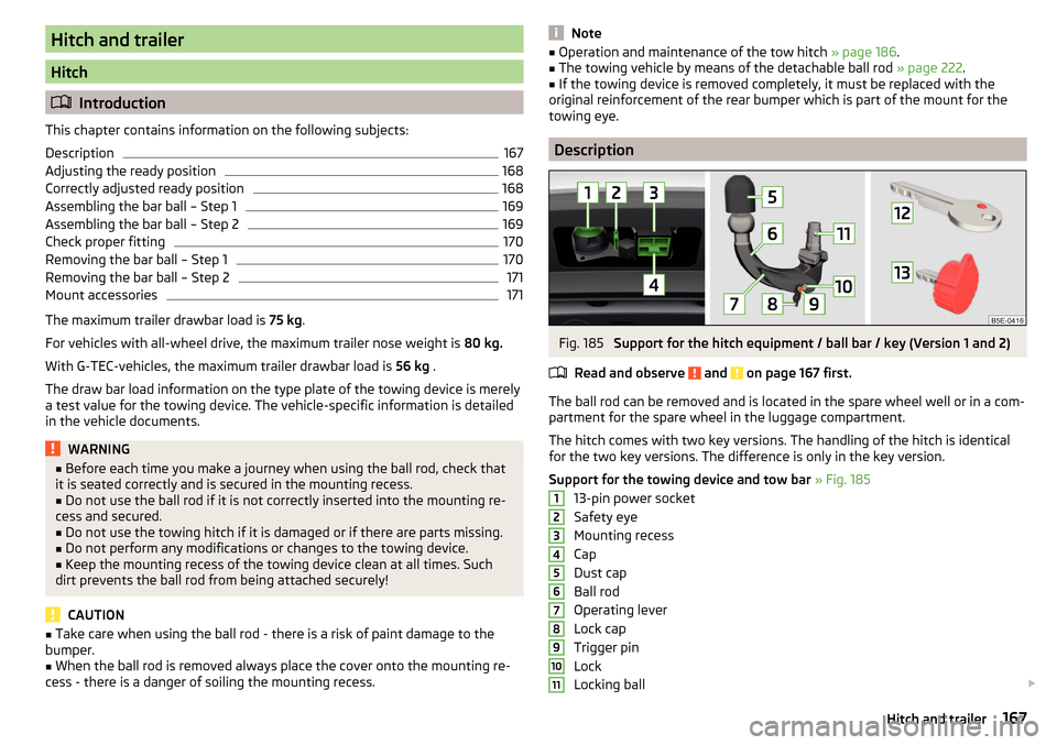
Fig. 185
Support for the hitch equipment / ball bar / key (Version 1 and 2)
Read and observe
and on page 167 first.
The ball rod can be removed and is located in the spare wheel well or in a com-
partment for the spare wheel in the luggage compartment.
The hitch comes with two key versions. The handling of the hitch is identical
for the two key versions. The difference is only in the key version.
Support for the towing device and tow bar » Fig. 185
13-pin power socket
Safety eye
Mounting recess
Cap
Dust cap
Ball rod
Operating lever
Lock cap
Trigger pin
Lock
Locking ball
1234567891011167Hitch and trailer
Page 170 of 268

Key – Version 1
Key – Version 2
Note
If you lose the key, please get in touch with a specialist garage.
Adjusting the ready position
Fig. 186
Gear 1 Step: Key Version 1 / key Version 2
Fig. 187
Step 2: Both key versions
Read and observe and on page 167 first.
The ball rod must be set to the ready position prior to installation » page 168,
Correctly adjusted ready position .
If it is not in the ready position, then it must be set to the ready position as
follows.
Gear 1 Step - applies to the key version 1
›
Remove the cap from the lock
›
Insert key
A
into the lock so that the green marking is pointing upwards.
1213› Turn key A in the direction of arrow 1 so that the red marking is pointing
upwards » Fig. 186 .
Gear 1 Step - applies to the key version 2›
Remove the cap from the lock
›
Insert key
B
into the lock so that the eye of the key is pointing downwards.
›
Turn the key in the direction of arrow
B
2
so that the conclusions release
shows up » Fig. 186.
Gear 2 Step - applies to both key versions
›
Grip the tow bar below the protective cap.
›
Push release pin
C
in the direction of arrow
3
to the stop, and simultane-
ously push operating lever
D
in the direction of arrow
4
to the stop
» Fig. 187 .
Operating lever
D
remains locked in this position.
Correctly adjusted ready position
Fig. 188
Ready position: Key Version 1 / key Version 2 / position of the
lever and the release bolt with two key versions
Read and observe
and on page 167 first.
Correctly adjusted standby position » Fig. 188
Applies to key version 1 - the red marking on key
A
is pointing upwards.
Applies to key version 2 - the eye of the key
B
is pointing upwards.
Operating lever
C
is locked in the lower position.
The trigger pin
D
can be moved.
The ball bar is thus set ready for installation.
168Driving
Page 171 of 268
CAUTIONIn the ready position, the key cannot be removed nor turned into a different
position.
Assembling the bar ball – Step 1
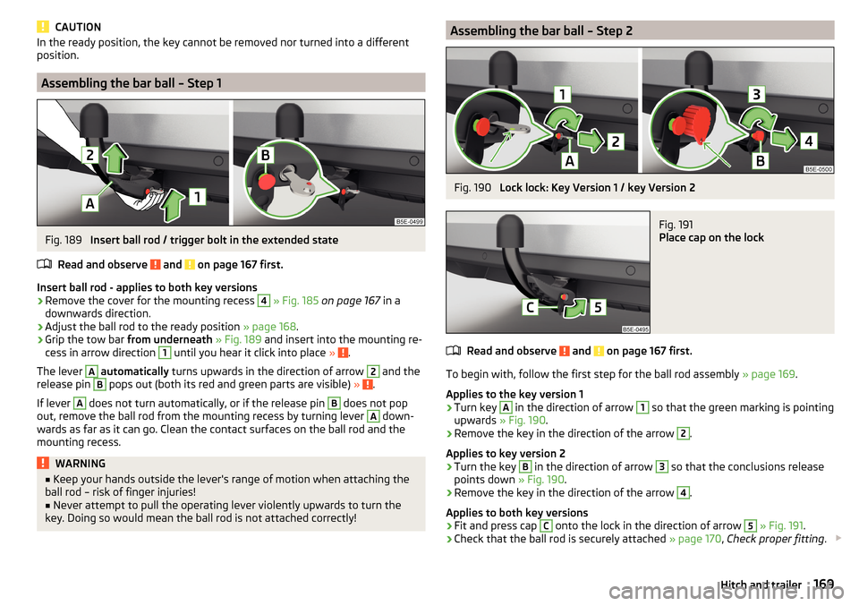
Fig. 189
Insert ball rod / trigger bolt in the extended state
Read and observe
and on page 167 first.
Insert ball rod - applies to both key versions
›
Remove the cover for the mounting recess
4
» Fig. 185 on page 167 in a
downwards direction.
›
Adjust the ball rod to the ready position » page 168.
›
Grip the tow bar from underneath » Fig. 189 and insert into the mounting re-
cess in arrow direction
1
until you hear it click into place » .
The lever
A
automatically turns upwards in the direction of arrow
2
and the
release pin
B
pops out (both its red and green parts are visible) » .
If lever
A
does not turn automatically, or if the release pin
B
does not pop
out, remove the ball rod from the mounting recess by turning lever
A
down-
wards as far as it can go. Clean the contact surfaces on the ball rod and the
mounting recess.
WARNING■ Keep your hands outside the lever's range of motion when attaching the
ball rod – risk of finger injuries!■
Never attempt to pull the operating lever violently upwards to turn the
key. Doing so would mean the ball rod is not attached correctly!
Assembling the bar ball – Step 2Fig. 190
Lock lock: Key Version 1 / key Version 2
Fig. 191
Place cap on the lock
Read and observe and on page 167 first.
To begin with, follow the first step for the ball rod assembly » page 169.
Applies to the key version 1
›
Turn key
A
in the direction of arrow
1
so that the green marking is pointing
upwards » Fig. 190 .
›
Remove the key in the direction of the arrow
2
.
Applies to key version 2
›
Turn the key
B
in the direction of arrow
3
so that the conclusions release
points down » Fig. 190.
›
Remove the key in the direction of the arrow
4
.
Applies to both key versions
›
Fit and press cap
C
onto the lock in the direction of arrow
5
» Fig. 191 .
›
Check that the ball rod is securely attached » page 170, Check proper fitting .
169Hitch and trailer
Page 172 of 268

CAUTIONAfter removing the key, always replace the cover on the lock – there is a risk of
the lock getting dirty.
Check proper fitting
Fig. 192
Correctly connected tow bar
Read and observe and on page 167 first.
Before each use of the ball rod, check that it is attached properly.
Correctly secured ball head » Fig. 192
The ball rod does not come off the mounting recess even after strong
“shaking”.
Operating lever
A
is as far up as possible.
The release pin
B
is completely exposed (both its red and green parts are
visible).
The key is removed.
The cap
B
is on the hand-wheel.
WARNINGDo not use the towing device unless the ball rod was properly locked!Removing the bar ball – Step 1Fig. 193
Remove the cap from the lock
Fig. 194
Unlock lock: Key version 1 / key version 2
Read and observe
and on page 167 first.
Applies to both key versions
›
Remove the cover
A
from the lock in the direction of the arrow
1
» Fig. 193 .
Applies to key version 1
›
Insert key
B
into the lock in the direction of arrow
2
so that the green
marking is pointing upwards.
›
Turn key
B
in the direction of arrow
3
so that the red marking is pointing
upwards » Fig. 194 .
Applies to key version 2
›
Insert key
C
into the lock in the direction of arrow
4
so that the eye of the
key is pointing downwards.
›
Turn key
C
in the direction of arrow
5
so that the eye of the key is pointing
upwards » Fig. 194 .
170Driving
Page 173 of 268
WARNINGNever remove the tow bar while the trailer is still coupled.
Note
We recommend putting the protective cover onto the ball head before remov-
ing the tow bar.
Removing the bar ball – Step 2
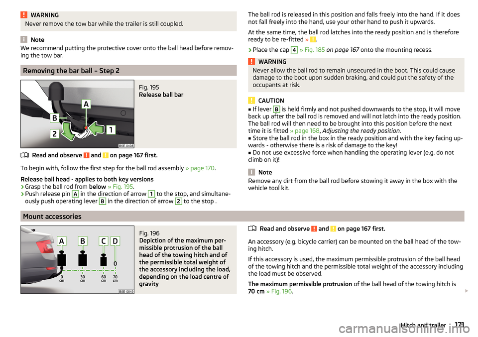
Fig. 195
Release ball bar
Read and observe and on page 167 first.
To begin with, follow the first step for the ball rod assembly » page 170.
Release ball head - applies to both key versions
›
Grasp the ball rod from below » Fig. 195 .
›
Push release pin
A
in the direction of arrow
1
to the stop, and simultane-
ously push operating lever
B
in the direction of arrow
2
to the stop .
The ball rod is released in this position and falls freely into the hand. If it does
not fall freely into the hand, use your other hand to push it upwards.
At the same time, the ball rod latches into the ready position and is therefore
ready to be re-fitted »
.
›
Place the cap
4
» Fig. 185 on page 167 onto the mounting recess.
WARNINGNever allow the ball rod to remain unsecured in the boot. This could cause
damage to the boot upon sudden braking, and could put the safety of the
occupants at risk.
CAUTION
■ If lever B is held firmly and not pushed downwards to the stop, it will move
back up after the ball rod is removed and will not latch into the ready position.
The ball rod will then need to be brought into this position before the next
time it is fitted » page 168, Adjusting the ready position .■
Store the ball rod in the box in the ready position and with the key facing up-
wards - otherwise there is a risk of damage to the key!
■
Do not use excessive force when handling the operating lever (e.g. do not
climb on it)!
Note
Remove any dirt from the ball rod before stowing it away in the box with the
vehicle tool kit.
Mount accessories
Fig. 196
Depiction of the maximum per-
missible protrusion of the ball
head of the towing hitch and of
the permissible total weight of
the accessory including the load,
depending on the load centre of
gravity
Read and observe and on page 167 first.
An accessory (e.g. bicycle carrier) can be mounted on the ball head of the tow-
ing hitch.
If this accessory is used, the maximum permissible protrusion of the ball head
of the towing hitch and the permissible total weight of the accessory including
the load must be observed.
The maximum permissible protrusion of the ball head of the towing hitch is
70 cm » Fig. 196 .
171Hitch and trailer
Page 215 of 268
CAUTION■Screw the jack back into the starting position before storing in the box with
the vehicle tool kit.■
Ensure that the vehicle tool kit is safely secured in the luggage compart-
ment.
■
Ensure that the box is always secured with the strap.
Note
The declaration of conformity is included with the jack or the log folder.
Changing a wheel
Introduction
This chapter contains information on the following subjects:
Preparation
213
Removing/stowing the wheel
213
Full wheel trim
213
Wheel bolts
214
Anti-theft wheel bolts
214
Loosening/tightening wheel bolts
215
Raising the vehicle
215
Remove the wheel / fix
216
Follow-up tasks
216
For your own safety and the safety of your passengers, the following instruc-
tions must be observed before carrying out a wheel change on the road.
Switch on the hazard warning light.
Place the warning triangle at the prescribed distance.
Park the vehicle as far away as possible from flowing traffic.
Choose a location with a flat, solid surface.
Have all the occupants get out. The passengers should not stand on the
road (instead they should remain behind a crash barrier, for instance) while
the wheel is being changed.
Preparation
Before changing the wheel, the following work must be carried out.
›
Switch off the engine.
› For vehicles with
manual transmission select 1st gear.›On vehicles with automatic transmission , place the selector lever in the P
position.›
The parking brake switch.
›
Uncouple any trailers.
Removing/stowing the wheel
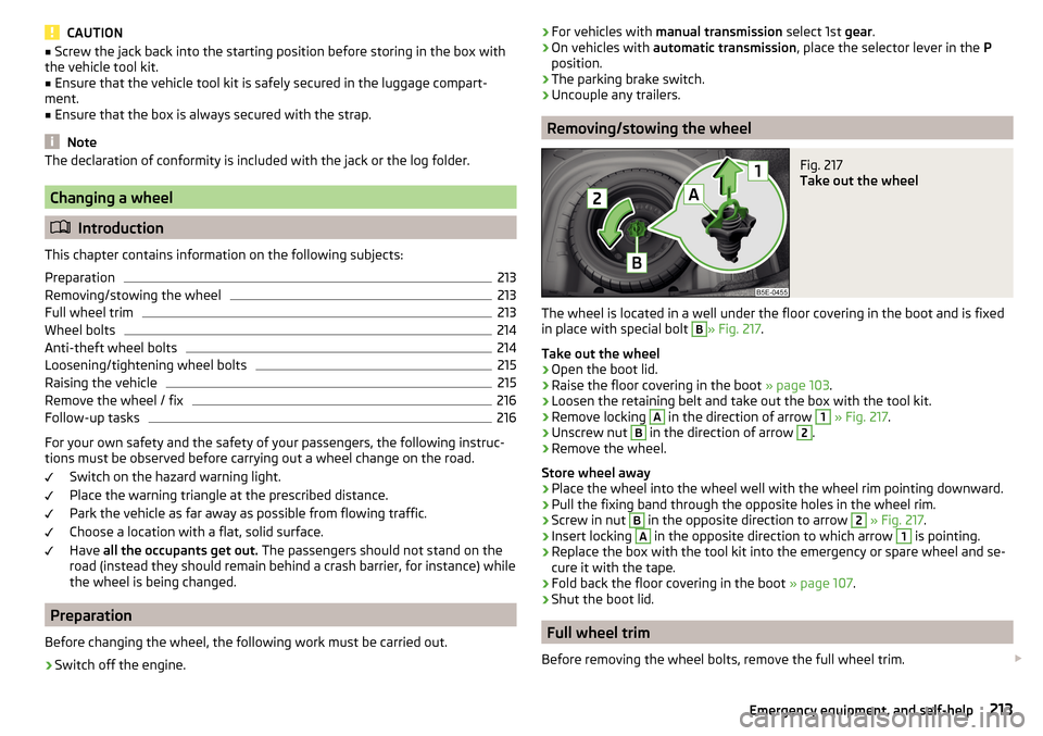
Fig. 217
Take out the wheel
The wheel is located in a well under the floor covering in the boot and is fixed
in place with special bolt
B
» Fig. 217 .
Take out the wheel
›
Open the boot lid.
›
Raise the floor covering in the boot » page 103.
›
Loosen the retaining belt and take out the box with the tool kit.
›
Remove locking
A
in the direction of arrow
1
» Fig. 217 .
›
Unscrew nut
B
in the direction of arrow
2
.
›
Remove the wheel.
Store wheel away
›
Place the wheel into the wheel well with the wheel rim pointing downward.
›
Pull the fixing band through the opposite holes in the wheel rim.
›
Screw in nut
B
in the opposite direction to arrow
2
» Fig. 217 .
›
Insert locking
A
in the opposite direction to which arrow
1
is pointing.
›
Replace the box with the tool kit into the emergency or spare wheel and se-
cure it with the tape.
›
Fold back the floor covering in the boot » page 107.
›
Shut the boot lid.
Full wheel trim
Before removing the wheel bolts, remove the full wheel trim.
213Emergency equipment, and self-help
Page 218 of 268
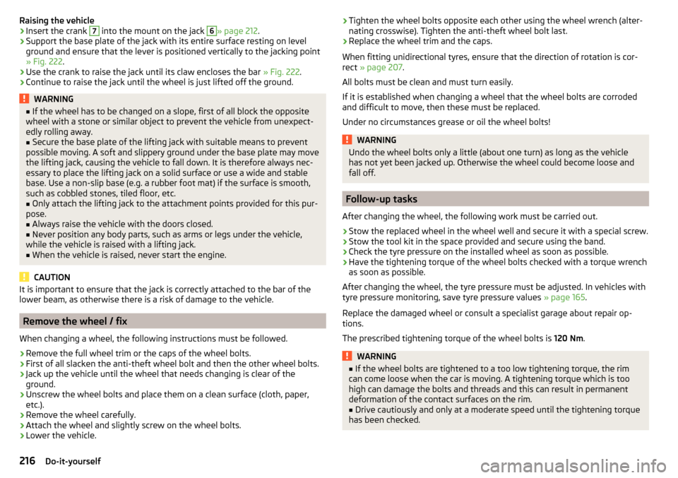
Raising the vehicle›Insert the crank 7 into the mount on the jack 6» page 212.›
Support the base plate of the jack with its entire surface resting on level
ground and ensure that the lever is positioned vertically to the jacking point
» Fig. 222 .
›
Use the crank to raise the jack until its claw encloses the bar » Fig. 222.
›
Continue to raise the jack until the wheel is just lifted off the ground.
WARNING■
If the wheel has to be changed on a slope, first of all block the opposite
wheel with a stone or similar object to prevent the vehicle from unexpect-
edly rolling away.■
Secure the base plate of the lifting jack with suitable means to prevent
possible moving. A soft and slippery ground under the base plate may move
the lifting jack, causing the vehicle to fall down. It is therefore always nec-
essary to place the lifting jack on a solid surface or use a wide and stable
base. Use a non-slip base (e.g. a rubber foot mat) if the surface is smooth,
such as cobbled stones, tiled floor, etc.
■
Only attach the lifting jack to the attachment points provided for this pur-
pose.
■
Always raise the vehicle with the doors closed.
■
Never position any body parts, such as arms or legs under the vehicle,
while the vehicle is raised with a lifting jack.
■
When the vehicle is raised, never start the engine.
CAUTION
It is important to ensure that the jack is correctly attached to the bar of the
lower beam, as otherwise there is a risk of damage to the vehicle.
Remove the wheel / fix
When changing a wheel, the following instructions must be followed.
›
Remove the full wheel trim or the caps of the wheel bolts.
›
First of all slacken the anti-theft wheel bolt and then the other wheel bolts.
›
Jack up the vehicle until the wheel that needs changing is clear of the
ground.
›
Unscrew the wheel bolts and place them on a clean surface (cloth, paper,
etc.).
›
Remove the wheel carefully.
›
Attach the wheel and slightly screw on the wheel bolts.
›
Lower the vehicle.
› Tighten the wheel bolts opposite each other using the wheel wrench (alter-
nating crosswise). Tighten the anti-theft wheel bolt last.›
Replace the wheel trim and the caps.
When fitting unidirectional tyres, ensure that the direction of rotation is cor-
rect » page 207 .
All bolts must be clean and must turn easily.
If it is established when changing a wheel that the wheel bolts are corroded and difficult to move, then these must be replaced.
Under no circumstances grease or oil the wheel bolts!
WARNINGUndo the wheel bolts only a little (about one turn) as long as the vehicle
has not yet been jacked up. Otherwise the wheel could become loose and
fall off.
Follow-up tasks
After changing the wheel, the following work must be carried out.
›
Stow the replaced wheel in the wheel well and secure it with a special screw.
›
Stow the tool kit in the space provided and secure using the band.
›
Check the tyre pressure on the installed wheel as soon as possible.
›
Have the tightening torque of the wheel bolts checked with a torque wrench
as soon as possible.
After changing the wheel, the tyre pressure must be adjusted. In vehicles with
tyre pressure monitoring, save tyre pressure values » page 165.
Replace the damaged wheel or consult a specialist garage about repair op-
tions.
The prescribed tightening torque of the wheel bolts is 120 Nm.
WARNING■
If the wheel bolts are tightened to a too low tightening torque, the rim
can come loose when the car is moving. A tightening torque which is too
high can damage the bolts and threads and this can result in permanent
deformation of the contact surfaces on the rim.■
Drive cautiously and only at a moderate speed until the tightening torque
has been checked.
216Do-it-yourself