engine SKODA OCTAVIA 2016 3.G / (5E) Owner's Guide
[x] Cancel search | Manufacturer: SKODA, Model Year: 2016, Model line: OCTAVIA, Model: SKODA OCTAVIA 2016 3.G / (5E)Pages: 324, PDF Size: 48.85 MB
Page 73 of 324

Windscreen and rear window heaterFig. 55
Buttons for the front and rear window heater: Climatronic / man-
ual air conditioning, heating
Read and observe
on page 70 first.
The heating for quick defrosting and ventilation of the front /and rear window.The heating only works when the engine is running.
Buttons for the heating (depending on vehicle equipment) » Fig. 55
Switch on/off the rear window heating
Switching the windscreen heater on/off
When the heating is switched on, a light illuminates inside or below the but-
ton.
The heating automatically switches off after 10 minutes.
If the engine is switched off when the heating is on and turned back on again
within 10 minutes, the heating is continued.
Note
■ If the on-board voltage decreases, the heating switches off automatically
» page 258 , Automatic consumer shutdown - Discharge protection of the vehi-
cle battery .■
If the lighting inside or below the button flashes, the heater will not work be-
cause of the low charge of the battery.
■
If the Climatronic recognises that the windshield could fog up, the windshield
heating is automatically switched on. This function can be activated / deactiva-
ted on the Climatronic control panel menu
→
.
Sun visorsFig. 56
Fold down visor / flip up visor / make-up mirror and Park Memo
Holder
Read and observe
on page 70 first.
Operation and description of the sun visor » Fig. 56
Swivel cover towards the windscreen
Swivel cover towards the door
Make-up mirror with cover (the cover can be pushed in the direction of the
arrow)
Parking ticket holder
Sunshade
Fig. 57
Sun screen
Read and observe on page 70 first.
The sun screen is located in a housing on the luggage compartment cover.
›
To dim pull the screen
B
out of the housing at the handle and hook into the
magnetic holders
A
» Fig. 57 .
12AB71Lights and visibility
Page 76 of 324
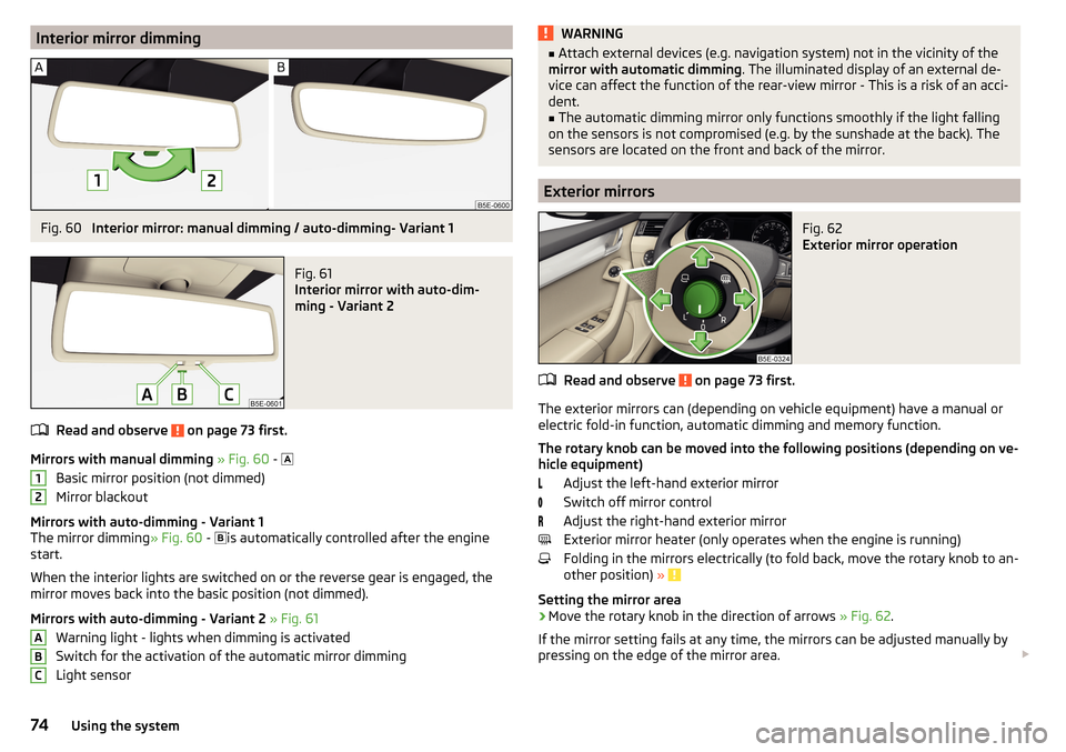
Interior mirror dimmingFig. 60
Interior mirror: manual dimming / auto-dimming- Variant 1
Fig. 61
Interior mirror with auto-dim-
ming - Variant 2
Read and observe on page 73 first.
Mirrors with manual dimming » Fig. 60 -
Basic mirror position (not dimmed)
Mirror blackout
Mirrors with auto-dimming - Variant 1
The mirror dimming » Fig. 60 -
is automatically controlled after the engine
start.
When the interior lights are switched on or the reverse gear is engaged, the
mirror moves back into the basic position (not dimmed).
Mirrors with auto-dimming - Variant 2 » Fig. 61
Warning light - lights when dimming is activated
Switch for the activation of the automatic mirror dimming
Light sensor
12ABCWARNING■ Attach external devices (e.g. navigation system) not in the vicinity of the
mirror with automatic dimming . The illuminated display of an external de-
vice can affect the function of the rear-view mirror - This is a risk of an acci-
dent.■
The automatic dimming mirror only functions smoothly if the light falling
on the sensors is not compromised (e.g. by the sunshade at the back). The
sensors are located on the front and back of the mirror.
Exterior mirrors
Fig. 62
Exterior mirror operation
Read and observe on page 73 first.
The exterior mirrors can (depending on vehicle equipment) have a manual or
electric fold-in function, automatic dimming and memory function.
The rotary knob can be moved into the following positions (depending on ve- hicle equipment)
Adjust the left-hand exterior mirror
Switch off mirror control
Adjust the right-hand exterior mirror
Exterior mirror heater (only operates when the engine is running)
Folding in the mirrors electrically (to fold back, move the rotary knob to an-
other position) »
Setting the mirror area
›
Move the rotary knob in the direction of arrows » Fig. 62.
If the mirror setting fails at any time, the mirrors can be adjusted manually by
pressing on the edge of the mirror area.
74Using the system
Page 83 of 324

›To
adjust the height , hold the locking button A and move the rest in the de-
sired direction » Fig. 71.
Setting the height of the rear headrests
Fig. 72
Setting the height of the back headrest
›
Grasp the headrest and move upwards in the direction of arrow
1
» Fig. 72 .
›
To move the headrest down, press the securing button
A
in the direction of
arrow
2
and hold it down while pressing the headrest in the direction of ar-
row
3
.
Removing/inserting the rear headrests
Fig. 73
Removing/inserting the rear headrests
Before removing/inserting the headrests, fold the corresponding seat backrest
slightly forward » page 79.
›
To remove the headrest, pull it out of the seat backrest up to the stop.
›Hold the locking button A in the direction of arrow 1, at the same time us-
ing a flat screwdriver with a max. width of 5 mm to press the locking button
in the opening B
in the direction of arrow
2
and pull out the rest in the di-
rection of arrow
3
» Fig. 73 .
›
To insert the headrest, push the headrest into the seat backrest in the direc-
tion of arrow
4
until the locking button clicks into place.
Seat heaters
Fig. 74
Buttons for heating the front seats/rear seats
The seat backrests and surfaces of the front seats and the outer rear seats
can be heated electrically.
Seat heating buttons » Fig. 74
Left seat heating
Right seat heating
›
To turn on the heating to max, press the key
or
button.
By repeatedly pressing the button, the heat is turned down until it is com-
pletely switched off . The level of the seat heating is indicated by the number
of illuminated warning lights underneath / in the button.
The seat heating only operates when the engine is running.
When the ignition is switched off, the seat heating / ventilation is also switch-
ed off. if the engine is started again within 10 minutes, then the driver's seat
heating / ventilation is switched on again automatically according to the set-
ting before switching off the ignition.
81Seats and head restraints
Page 92 of 324

CAUTIONNever fold and stow the through-loading bag when it is wet - There is a risk of
damaging the through-loading bag.
Electrical sockets
Introduction
This chapter contains information on the following subjects:
12-volt power outlet
90
230-volt socket
90WARNING■ Do not place anything on the dash panel. These objects might slide or fall
down when driving and may distract you from concentrating on the traffic –
There is a risk of an accident!■
Make sure that while driving no objects can enter the driver's footwell -
There is a risk of an accident!
■
Stow all devices safely during the journey to prevent them from being
thrown around the interior in the event of a sudden braking manoeuvre or
an accident – The is a risk to life!
■
The devices may warm up during operation – The is a risk of injury or fire!
■
Improper use of the power sockets and the electrical accessories can
cause fires, burns and other serious injuries.
■
The 12-Volt sockets also work if the ignition is switched off. When leaving
the vehicle, never leave persons who are not completely independent, such
as children, unattended in the vehicle.
CAUTION
When using the 12-volt sockets, the following notes are to be observed.■The sockets can only be used for the connection of approved electrical ac-
cessories with a total power consumption of up to 120 watts - otherwise the
there is a risk of damage to the electrical system of the vehicle.■
Connecting appliances when the engine is not running will drain the battery
of the vehicle!
■
Before switching the ignition on / off or before starting the engine, switch
off the devices which are connected to the sockets - there is a risk of damage
to the equipment due to voltage fluctuations.
12-volt power outletFig. 94
Cover of the 12 volt power outlet: in the front centre console/ in
the boot
Read and observe
and on page 90 first.
›
Touse , remove the cover of the socket » Fig. 94 -
or open the cover of the
socket » Fig. 94 -
.
›
Connect the plug for the electrical appliance to the socket.
230-volt socket
Fig. 95
Open the cover of the 230 volt
power outlet
Read and observe and on page 90 first.
The 230-volt socket has a child safety lock. When inserting the plug, the fuse
is released, the socket is activated and the warning light above the socket is
illuminates green (if this flashes red, then the socket is deactivated).
›
To use , fold up the cover of the socket in the direction of arrow » Fig. 95 and
plug the electrical appliance plug into the socket.
90Using the system
Page 106 of 324
Stowing the roof racks
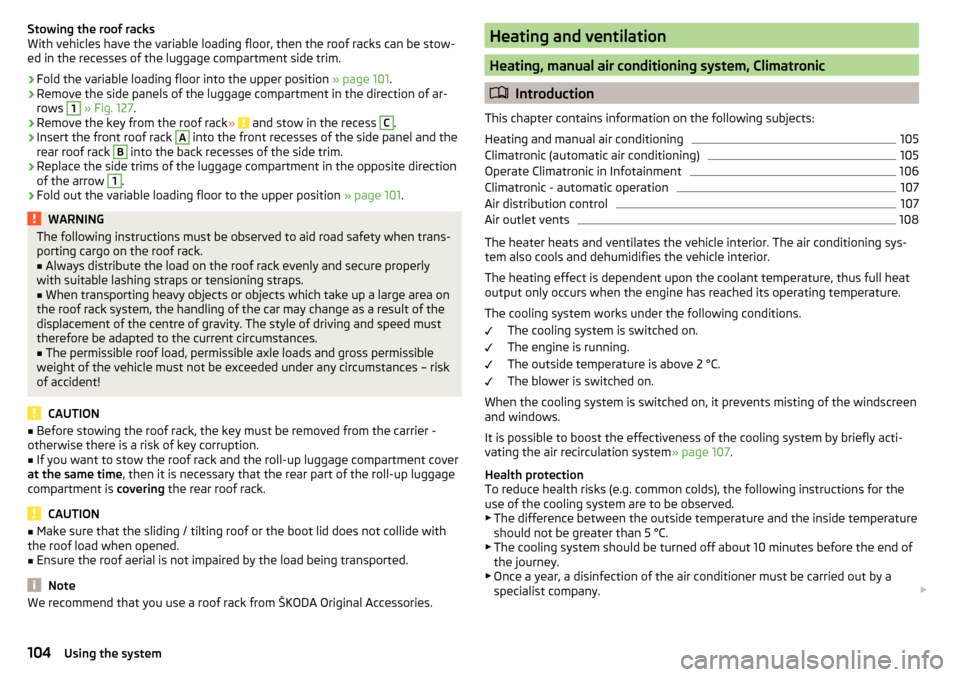
With vehicles have the variable loading floor, then the roof racks can be stow-
ed in the recesses of the luggage compartment side trim.›
Fold the variable loading floor into the upper position » page 101.
›
Remove the side panels of the luggage compartment in the direction of ar-
rows
1
» Fig. 127 .
›
Remove the key from the roof rack » and stow in the recess
C
.
›
Insert the front roof rack
A
into the front recesses of the side panel and the
rear roof rack
B
into the back recesses of the side trim.
›
Replace the side trims of the luggage compartment in the opposite direction
of the arrow
1
.
›
Fold out the variable loading floor to the upper position » page 101.
WARNINGThe following instructions must be observed to aid road safety when trans-
porting cargo on the roof rack.■
Always distribute the load on the roof rack evenly and secure properly
with suitable lashing straps or tensioning straps.
■
When transporting heavy objects or objects which take up a large area on
the roof rack system, the handling of the car may change as a result of the
displacement of the centre of gravity. The style of driving and speed must
therefore be adapted to the current circumstances.
■
The permissible roof load, permissible axle loads and gross permissible
weight of the vehicle must not be exceeded under any circumstances – risk
of accident!
CAUTION
■ Before stowing the roof rack, the key must be removed from the carrier -
otherwise there is a risk of key corruption.■
If you want to stow the roof rack and the roll-up luggage compartment cover
at the same time , then it is necessary that the rear part of the roll-up luggage
compartment is covering the rear roof rack.
CAUTION
■
Make sure that the sliding / tilting roof or the boot lid does not collide with
the roof load when opened.■
Ensure the roof aerial is not impaired by the load being transported.
Note
We recommend that you use a roof rack from ŠKODA Original Accessories.Heating and ventilation
Heating, manual air conditioning system, Climatronic
Introduction
This chapter contains information on the following subjects:
Heating and manual air conditioning
105
Climatronic (automatic air conditioning)
105
Operate Climatronic in Infotainment
106
Climatronic - automatic operation
107
Air distribution control
107
Air outlet vents
108
The heater heats and ventilates the vehicle interior. The air conditioning sys-
tem also cools and dehumidifies the vehicle interior.
The heating effect is dependent upon the coolant temperature, thus full heat
output only occurs when the engine has reached its operating temperature.
The cooling system works under the following conditions. The cooling system is switched on.
The engine is running.
The outside temperature is above 2 °C.
The blower is switched on.
When the cooling system is switched on, it prevents misting of the windscreen
and windows.
It is possible to boost the effectiveness of the cooling system by briefly acti-
vating the air recirculation system » page 107.
Health protection
To reduce health risks (e.g. common colds), the following instructions for the
use of the cooling system are to be observed. ▶ The difference between the outside temperature and the inside temperature
should not be greater than 5 °C.
▶ The cooling system should be turned off about 10 minutes before the end of
the journey.
▶ Once a year, a disinfection of the air conditioner must be carried out by a
specialist company.
104Using the system
Page 107 of 324
WARNING■The blower should always be on to prevent the windows from misting.
Otherwise there is a risk of an accident.■
Under certain circumstances, air at a temperature of about 5 °C can flow
out of the vents when the cooling system is switched on.
Note
■ The air inlet in front of the windscreen must be free of e.g. ice, snow or
leaves to ensure that the heating and cooling system operates properly.■
After switching on the cooling Condensation from the evaporator of the air
conditioning may drip down and form a puddle below the vehicle. This is not a
leak!
■
If the coolant temperature is too high, the cooling system is switched off to
ensure that the engine cools down.
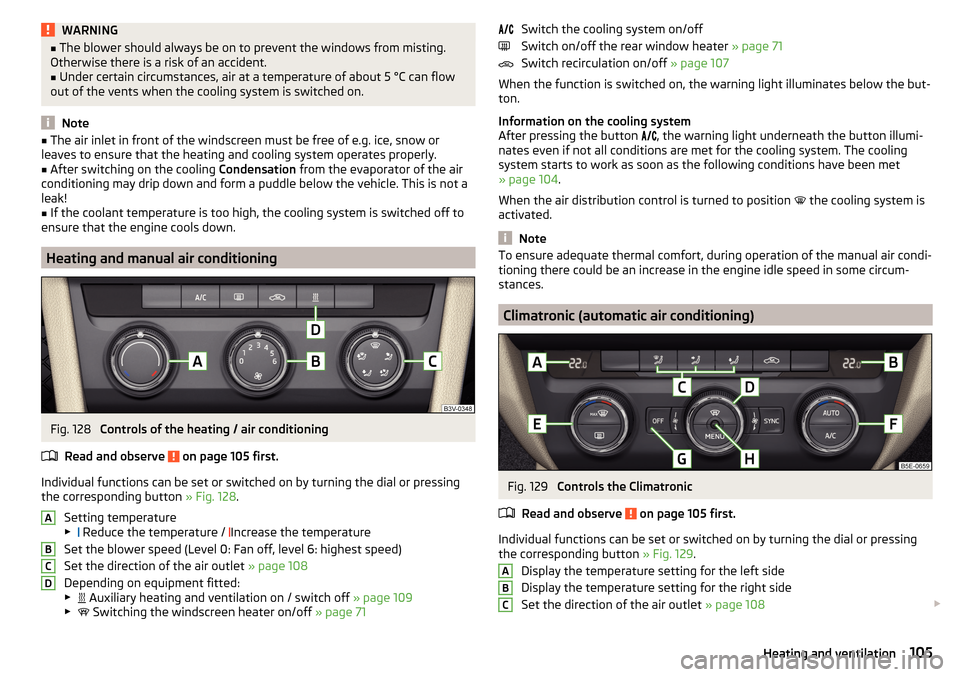
Heating and manual air conditioning
Fig. 128
Controls of the heating / air conditioning
Read and observe
on page 105 first.
Individual functions can be set or switched on by turning the dial or pressing the corresponding button » Fig. 128.
Setting temperature
▶ Reduce the temperature /
Increase the temperature
Set the blower speed (Level 0: Fan off, level 6: highest speed)
Set the direction of the air outlet » page 108
Depending on equipment fitted:
▶ Auxiliary heating and ventilation on / switch off
» page 109
▶ Switching the windscreen heater on/off
» page 71
ABCDSwitch the cooling system on/off
Switch on/off the rear window heater » page 71
Switch recirculation on/off » page 107
When the function is switched on, the warning light illuminates below the but-
ton.
Information on the cooling system
After pressing the button
, the warning light underneath the button illumi-
nates even if not all conditions are met for the cooling system. The cooling
system starts to work as soon as the following conditions have been met
» page 104 .
When the air distribution control is turned to position the cooling system is
activated.
Note
To ensure adequate thermal comfort, during operation of the manual air condi-
tioning there could be an increase in the engine idle speed in some circum-
stances.
Climatronic (automatic air conditioning)
Fig. 129
Controls the Climatronic
Read and observe
on page 105 first.
Individual functions can be set or switched on by turning the dial or pressing the corresponding button » Fig. 129.
Display the temperature setting for the left side
Display the temperature setting for the right side
Set the direction of the air outlet » page 108
ABC105Heating and ventilation
Page 110 of 324
CAUTIONWe recommend not smoking in the vehicle when the recirculating air operation
is switched on. The smoke sucked from the interior is deposited on the evapo-
rator of the air conditioner. This produces a permanent odour when the air
conditioning system is operating which can only be eliminated through consid-
erable effort and expense (replacement of compressor).
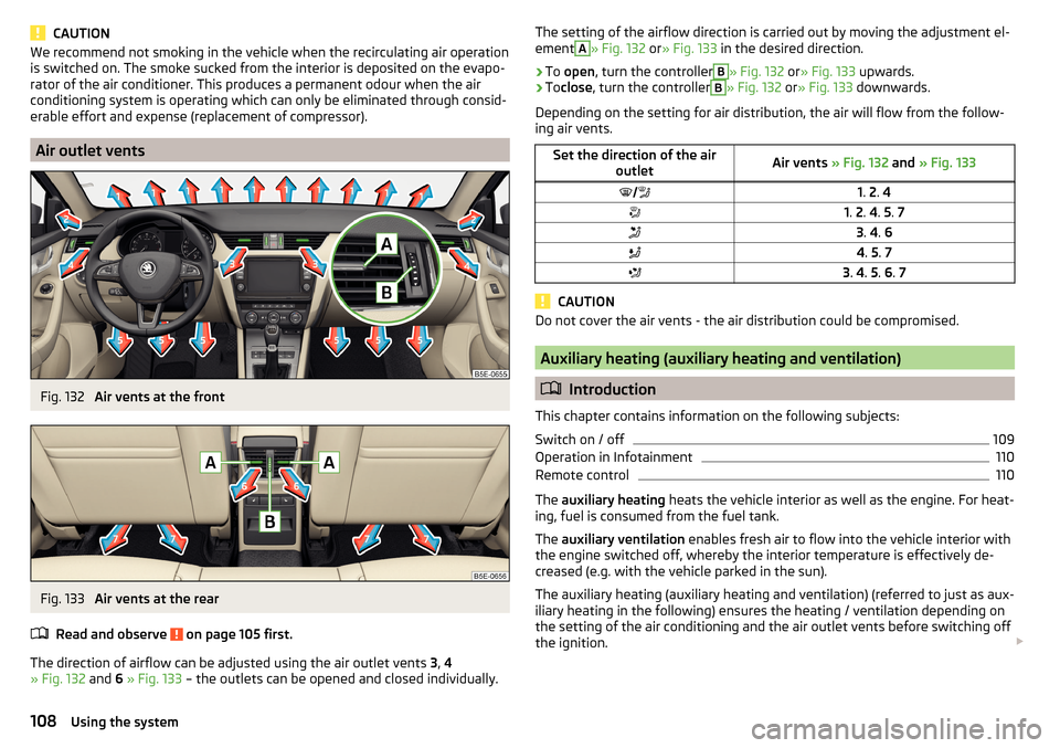
Air outlet vents
Fig. 132
Air vents at the front
Fig. 133
Air vents at the rear
Read and observe
on page 105 first.
The direction of airflow can be adjusted using the air outlet vents 3, 4
» Fig. 132 and 6 » Fig. 133 – the outlets can be opened and closed individually.
The setting of the airflow direction is carried out by moving the adjustment el-
ementA» Fig. 132 or» Fig. 133 in the desired direction.›
To open , turn the controller
B
» Fig. 132 or» Fig. 133 upwards.
›
Toclose , turn the controller
B
» Fig. 132 or» Fig. 133 downwards.
Depending on the setting for air distribution, the air will flow from the follow-
ing air vents.
Set the direction of the air outletAir vents » Fig. 132 and » Fig. 1331. 2 . 41. 2 . 4 . 5 . 73 . 4 . 64 . 5 . 73 . 4 . 5 . 6 . 7
CAUTION
Do not cover the air vents - the air distribution could be compromised.
Auxiliary heating (auxiliary heating and ventilation)
Introduction
This chapter contains information on the following subjects:
Switch on / off
109
Operation in Infotainment
110
Remote control
110
The auxiliary heating heats the vehicle interior as well as the engine. For heat-
ing, fuel is consumed from the fuel tank.
The auxiliary ventilation enables fresh air to flow into the vehicle interior with
the engine switched off, whereby the interior temperature is effectively de-
creased (e.g. with the vehicle parked in the sun).
The auxiliary heating (auxiliary heating and ventilation) (referred to just as aux- iliary heating in the following) ensures the heating / ventilation depending on
the setting of the air conditioning and the air outlet vents before switching off
the ignition.
108Using the system
Page 111 of 324
WARNING■The auxiliary heating must never be operated in closed rooms (e.g. garag-
es) – risk of poisoning!■
The auxiliary heating must not be allowed to run during refuelling – risk
of fire.
■
The exhaust pipe of the auxiliary heating is located on the underside of
the vehicle. If you want to use the auxiliary heating, do not park the vehicle
in places where the exhaust fumes can come into contact with flammable
materials such as dry grass, undergrowth, leaves, spilled fuel etc. - There is
a risk of fire.
CAUTION
The air inlet in front of the windscreen must be free (e.g. of ice, snow or
leaves) to ensure that the auxiliary heating operates properly.
Note
■ The auxiliary heating only switches the blower on, if it has achieved a coolant
temperature of approx. 50 °C.■
In the engine compartment, water vapour may form during the operation of
the heater.
Switch on / off
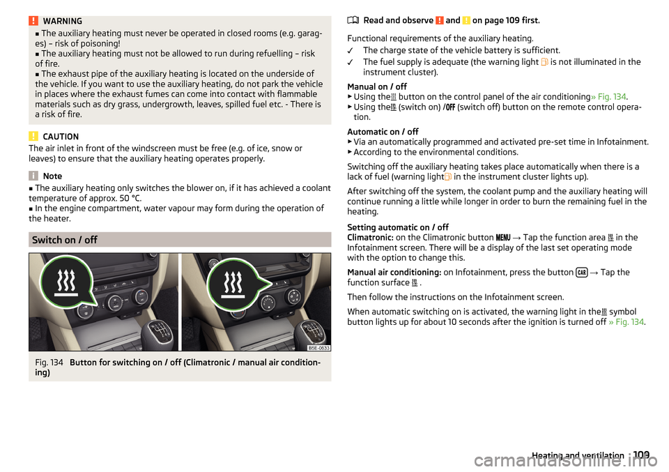
Fig. 134
Button for switching on / off (Climatronic / manual air condition-
ing)
Read and observe and on page 109 first.
Functional requirements of the auxiliary heating.
The charge state of the vehicle battery is sufficient.
The fuel supply is adequate (the warning light
is not illuminated in the
instrument cluster).
Manual on / off ▶ Using the
button on the control panel of the air conditioning » Fig. 134.
▶ Using the
(switch on) /
(switch off) button on the remote control opera-
tion.
Automatic on / off ▶ Via an automatically programmed and activated pre-set time in Infotainment.
▶ According to the environmental conditions.
Switching off the auxiliary heating takes place automatically when there is a
lack of fuel (warning light in the instrument cluster lights up).
After switching off the system, the coolant pump and the auxiliary heating will
continue running a little while longer in order to burn the remaining fuel in the
heating.
Setting automatic on / off
Climatronic: on the Climatronic button
→ Tap the function area
in the
Infotainment screen. There will be a display of the last set operating mode
with the option to change this.
Manual air conditioning: on Infotainment, press the button
→ Tap the
function surface .
Then follow the instructions on the Infotainment screen.
When automatic switching on is activated, the warning light in the symbol
button lights up for about 10 seconds after the ignition is turned off » Fig. 134.
109Heating and ventilation
Page 119 of 324

Operating the menusFig. 146
Operating the menus
Operating the menus » Fig. 146
Reduction / enlargement of the menu window Browse the menu- List entries Open / close the menu window
Close the menu window
Alphanumeric keyboard
Fig. 147
Example of the keyboard display
The alphanumeric keypad is used to enter for letters, numbers and characters.
Description of the alphanumeric keyboard » Fig. 147
Input line
Context-dependent: ▶ - Switch to capital letters
▶ - Switch to special characters
▶ - Switch to numbers
ABContext-dependent:
▶ - Switch to numbers
▶ - Switch to Latin letters
▶
- Switch to Cyrillic letters
- Display of visited entries (the number of visited entries is displayed in the
function surface)
Erase the entered characters
By holding the variants of each type are displayed.
Switching between keyboards with specific characters of the selected lan-
guages » page 123 or. » page 130
Enters a blank
Move the cursor within the input line to the left
Move the cursor within the input line to the right
Confirmation of the entered number
Search
While entering characters, a search is made for corresponding entries.
The entry such as a telephone contact to be searched for must be entered
along with the special characters (diacritics).
By tapping on the function surface A list of matching entries opens.
Switching Infotainment on / off
›
To
switch on/off Infotainment, press .
Automatic switch-on of Infotainment
If Infotainment was not turned off with the control switch
before the igni-
tion was turned off, it will automatically switch on after the ignition is switch-
ed on.
Automatic switch-off of Infotainment
If the vehicle key is pulled out of the ignition lock while Infotainment is switch-
ed on, Infotainment will switch off automatically.
If the vehicle is fitted with the starter button, Infotainment will switch off au-
tomatically after the engine is switched off and the door is opened.
With the ignition off, Infotainment will automatically turn off after about 30
minutes.
Infotainment turns off automatically under certain circumstances. Infotain-
ment informs of this via a text message on the Infotainment display.
C117Infotainment operation
Page 190 of 324
Driving
Starting-off and Driving
Starting and stopping the engine
Introduction
This chapter contains information on the following subjects:
Electronic immobiliser and steering lock
188
Switch on/off ignition
189
Starting / stopping the engine
189
Problems with the engine start - vehicles with starter button
190
Depending on equipment fitted, it is possible to switch the ignition on/off and
start/stop the engine with the key in the ignition or using the starter button .
WARNING■
Never switch off the engine before the vehicle is stationary – risk of acci-
dent!■
While driving with the engine stopped the ignition must always be
switched on. Otherwise, the steering may lock - danger of an accident!
■
Do not withdraw the ignition key from the ignition lock until the vehicle
has come to a stop » page 193, Parking . Otherwise, the steering may lock -
danger of an accident!
■
Never leave the vehicle unattended with the engine running - there is a
risk of theft etc!
■
Never (e.g. in garages) run the engine in a closed place - there is a risk of
poisoning and death!
CAUTION
■ Only start the engine when the engine and the vehicle are stationary - there
is a risk of starter and engine damage!■
Do not push-start the engine – There is a risk of damaging the engine and
the catalytic converter! The battery from another vehicle can be used as a
jump-start aid.
■
On vehicles with the starter button, pay attention to where the key is loca-
ted. The system can recognize the valid key, even if it has been accidentally
left on the vehicle roof - there is danger of loss or damage to the key!
NoteDo not warm up the engine while the vehicle is stationary. If possible, start
your journey as soon as the engine has started. Through this, the engine rea-
ches its operating temperature faster.
Electronic immobiliser and steering lock
Read and observe
and on page 188 first.
The electronic immobiliser (hereinafter referred to as immobiliser) makes the
theft or unauthorised use of your vehicle more difficult.
Immobiliser
The immobiliser allows the engine to start provided an original vehicle key only
is used.
Malfunction of the immobiliser
If a component in the immobiliser key fails, it is not possible to start the en-
gine. A corresponding message appears in the display of the instrument clus-
ter to explain the immobiliser is active.
To start, use the other vehicle key or seek help from a specialist garage.
Steering lock - locking
›
On vehicles with ignition lock, remove the key and turn the steering wheel
until the steering lock engages.
›
On vehicles with a starter button, switch off the ignition and open the driv-
er's door. If the driver's door is opened and the ignition is switched off after-
wards, the steering is only locked automatically after the vehicle has been
locked.
Steering lock - unlock
›
On vehicles with ignition lock, insert the key into the ignition and turn on the
ignition. If this is not possible, then move the steering wheel slightly back
and forth, as a result of which the steering lock should unlock.
›
On vehicles with starter button, get into the vehicle and close the driver's
door. Under certain circumstances, the steering lock can be unlocked only
when the ignition is switched on or the engine is started.
WARNINGNever let the vehicle roll with locked steering lock - there is a risk of acci-
dent!188Driving