SKODA OCTAVIA TOUR 2009 1.G / (1U) Owner's Guide
Manufacturer: SKODA, Model Year: 2009, Model line: OCTAVIA TOUR, Model: SKODA OCTAVIA TOUR 2009 1.G / (1U)Pages: 224, PDF Size: 13.53 MB
Page 21 of 224
Instruments and Indicator/Warning Lights
20
The multi-functional indicator offers
you a range of useful information.
Note
In certain national versions the displays
appear in the Imperial system of
measures.MemoryThe multi-functional indicator is eq
uipped with two automatic memories.
The data of the single-trip memory (memory 1) is shown if a
1 appears in the
display. A
2 shown in the display means that da
ta relates to the total distance
memory (memory 2). Switching of the memory takes place when the button
⇒fig. 21
.
Single-trip memory (memory 1) The single-trip memory collates the driving information from the moment the igni- tion is switched on until it
is switched off. New data will
also flow into the calcula-
tion of the current driving information if the trip is continued
within 2 hours
after
switching off the ignition. The memory will
be is automatically erased, on the other
hand, if the trip is interrupted for
more than 2 hours
.
Total-trip memory (memory 2) The total distance driven memory gathers
data from any number of individual jour-
neys up to a total of 99 hours and 59 minutes driving or 9.999 kilometres driven. The memory is deleted when either of these limits is reached and the calculation starts from anew. The total-trip memory will not, contrary to
the single-trip memory, be deleted after
a period of interruption of driving of 2 hours.
Note
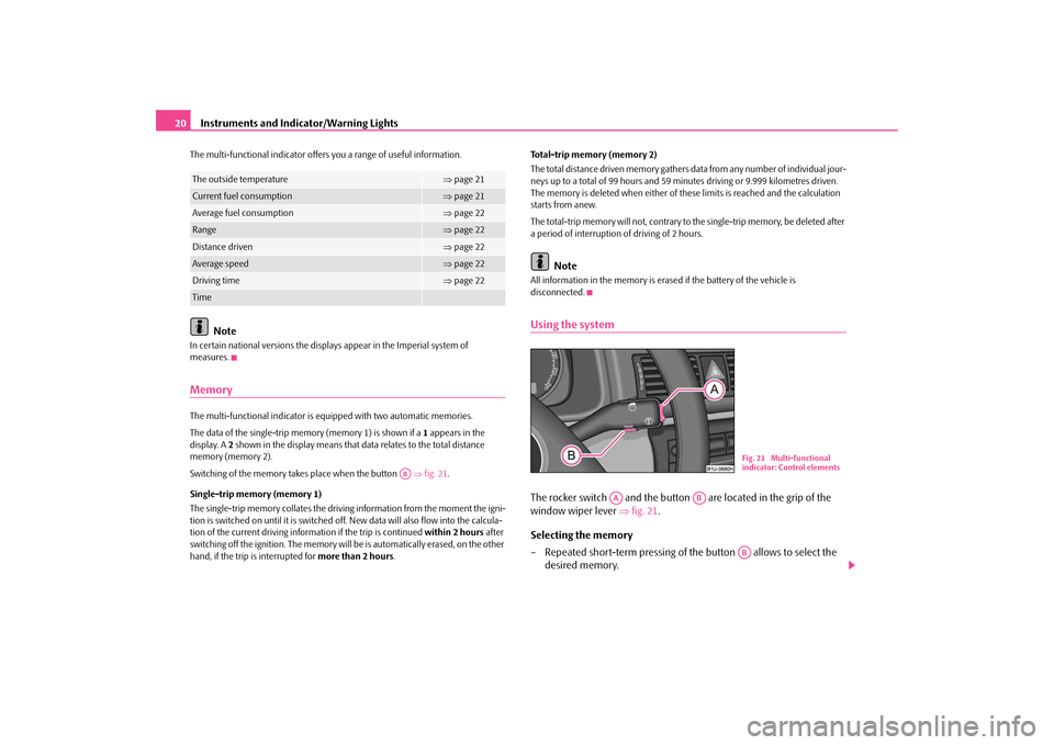
All information in the memory is erased if the battery of the vehicle is disconnected.Using the systemThe rocker switch and the button are located in the grip of the window wiper lever
⇒
fig. 21
.
Selecting the memory – Repeated short-term pressing of th
e button allows to select the
desired memory.
The outside temperature
⇒ page 21
Current fuel consumption
⇒page 21
Average fuel consumption
⇒page 22
Range
⇒page 22
Distance driven
⇒page 22
Average speed
⇒page 22
Driving time
⇒page 22
Time
AB
Fig. 21 Multi-functional indicator: Control elements
AA
AB
AB
s2g8.b.book Page 20 Tuesday, April 7, 2009 8:53 AM
Page 22 of 224
Instruments and Indicator/Warning Lights
21
Using the system
Safety
Driving Tips
General Maintenance
Breakdown assistance
Technical Data
Selecting the functions – Press the rocker switch up or down. This will cause the individual
functions of the multi-f
unctional indicator to
appear in the display
one after the other.
Setting function to zero – Select the memory you want. – Press button for more than 1 second.The following readouts of the selected me
mory will be set to zero by button :
•
average fuel consumption,
•
distance driven,
•
average speed,
•
Driving time.
You can only operate the multi-functional
indicator when the ignition is switched
on. After the ignition is switched on, the fu
nction displayed is the one which you last
selected before switching off the ignition. If the outside temperature drops below
+4 °C, the outside temperature indicator
with a snow flake symbol appears. The symbol warns the driver of the possible danger of ice on the road. After the rock
er switch is pressed, the function
displays the one which you last selected before switching off the ignition.
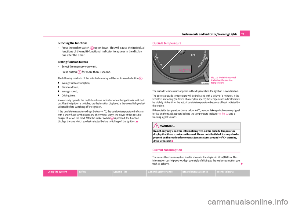
Outside temperatureThe outside temperature appears in the disp
lay when the ignition is switched on.
The correct outside temperature will be indi
cated with a delay of
5 minutes. If the
vehicle is stationary (or driven at a very low speed) the temperature indicated may be slightly higher than the actual outsid
e temperature because of
heat radiated by
the engine. If the outside temperature drops below +4°C
, a snow flake symbol (warning signal
for ice on the road) appears be
hind the temperature indicator
⇒fig. 22
and a
warning signal sounds.
WARNING
Do not only rely upon the information given on the outside temperature display that there is no ice on the road.
Please note that bl
ack ice may also be
present on the road surface even at
temperatures around +4°C - warning,
drive with care!Current consumptionThe current fuel consumption level is shown in the display in litres/100 km. This information can help you to adapt your styl
e of driving to the fuel consumption you
wish to achieve.
AA
AB
AB
AA
Fig. 22 Multi-functional indicator: the outside temperature
s2g8.b.book Page 21 Tuesday, April 7, 2009 8:53 AM
Page 23 of 224
Instruments and Indicator/Warning Lights
22
The display appears in litres/hour if the vehicle is stationary or driving at a low speed.Average fuel consumptionThe average fuel consumption since the memory was last erased is shown in the display in litres/100 km
⇒page 20. This information can help you to adapt your
style of driving to the fuel co
nsumption you wish to achieve.
If you wish to determine the average fuel
consumption over a cert
ain period of time
you must first erase the memory at the start of the new measurement using the button
⇒page 20, fig. 21
. A zero appears in the display for the first 300 m you
drive after erasing the memory. The indicated value will be updated every 5 seconds while you are driving.
Note
The amount of fuel consumed will not be indicated.RangeThe estimated range in kilometres is shown on the display. It indicates the distance you can still drive with your vehicle based on the present level of fuel in the tank for the same style of driving. The readout is shown in steps of 10 km. The fuel consumption for the last 50 km is
taken as a basis for calculating the range.
If you drive in a more economical manner from this moment on, the range will be increased accordingly. You first drive 50 km if the readout is reset (after disconnecting the battery) before a new readout for the range is displayed.Distance drivenThe distance driven since the memory was last erased appears in the display ⇒ page 20. If you wish to calculate the distance driven from a particular time of day
you must first erase the memory at this mo
ment in time by pressing the button
⇒ page 20, fig. 21
.
The maximum distance indicated in both sw
itch positions is 9 999 km. The indicator
is set back to null if th
is period is exceeded.
Average speedThe average speed since the memory was last erased is shown in the display in km/hour
⇒page 20. If you wish to determine
the average speed over a certain
period of time you must first erase the memory at the start of the new measure- ment using the button
⇒page 20, fig. 21
.
A zero appears in the display for the first 300 m you drive after erasing the memory.The indicated value will be updated every 5 seconds while you are driving.Driving timeThe driving time which has elapsed since the memory was last erased, appears in the display
⇒page 20. If you wish to calculate th
e driving time from a particular
time of day you must first erase the memory at this moment in time by pressing the button
⇒page 20, fig. 21
.
The maximum distance indi
cated in both memories is 99 hours and 59 minutes.
The indicator is set back to null
if this period is exceeded.
Warning against excessive speeds*An acoustic warning signal will sound
when the vehicle speed exceeds 120 kilome-
tres per hour. The acoustic warning signal
will switch off again when the vehicle
speed goes below this speed limit. This function is only vali
d for some export countries.
AB
AB
AB
AB
s2g8.b.book Page 22 Tuesday, April 7, 2009 8:53 AM
Page 24 of 224
Instruments and Indicator/Warning Lights
23
Using the system
Safety
Driving Tips
General Maintenance
Breakdown assistance
Technical Data
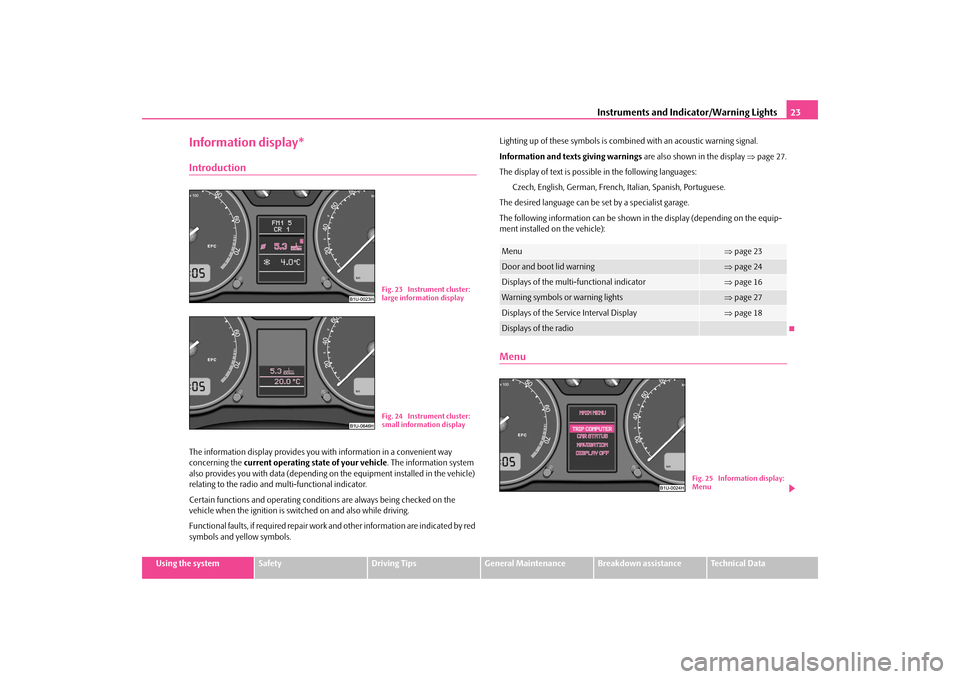
Information display*IntroductionThe information display provides you with information in a convenient way concerning the
current operating state of your vehicle
. The information system
also provides you with data (depending on the equipment installed in the vehicle) relating to the radio and multi-functional indicator. Certain functions and oper
ating conditions are always being checked on the
vehicle when the ignition is switched on and also while driving. Functional faults, if required
repair work and other information are indicated by red
symbols and yellow symbols.
Lighting up of these symbols is combined with an acoustic warning signal. Information and texts giving warnings
are also shown in the display
⇒page 27.
The display of text is possible in the following languages:
Czech, English, German, French,
Italian, Spanish, Portuguese.
The desired language can be
set by a specialist garage.
The following information can be shown in
the display (depending on the equip-
ment installed on the vehicle):Menu
Fig. 23 Instrument cluster: large information displayFig. 24 Instrument cluster: small information display
Menu
⇒ page 23
Door and boot lid warning
⇒page 24
Displays of the multi-functional indicator
⇒page 16
Warning symbols or warning lights
⇒page 27
Displays of the Service Interval Display
⇒page 18
Displays of the radio
Fig. 25 Information display: Menu
s2g8.b.book Page 23 Tuesday, April 7, 2009 8:53 AM
Page 25 of 224
Instruments and Indicator/Warning Lights
24
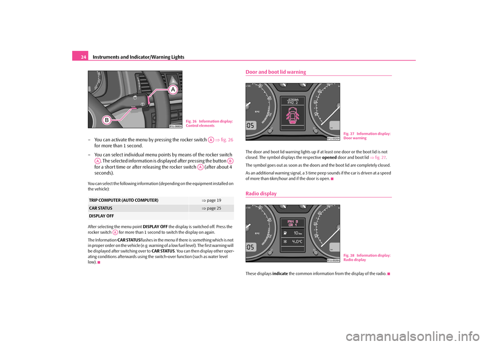
– You can activate the menu by pressing the rocker switch
⇒
fig. 26
for more than 1 second.
– You can select individual menu poin
ts by means of the rocker switch
. The selected information is displayed after pressing the button
for a short time or after releasing the rocker switch (after about 4 seconds).
You can select the following information (d
epending on the equipment installed on
the vehicle): After selecting the menu point
DISPLAY OFF
the display is switched off. Press the
rocker switch for more than 1 seco
nd to switch the display on again.
The Information
CAR STATUS
flashes in the menu if there is something which is not
in proper order on the vehicle (e.g. warning
of a low fuel level). The first warning will
be displayed after switching over to
CAR STATUS
. You can then display other oper-
ating conditions afterwards using the switch-over function (such as water level low).
Door and boot lid warningThe door and boot lid warning lights up if
at least one door or the boot lid is not
closed. The symbol displays the respective
opened
door and boot lid
⇒fig. 27
.
The symbol goes out as soon as the doors and the boot lid are completely closed.As an additional warning signal, a 3 time pe
ep sounds if the car is driven at a speed
of more than 6km/hour and if the door is open.Radio displayThese displays
indicate
the common information from the display of the radio.
TRIP COMPUTER (AUTO COMPUTER)
⇒page 19
CAR STATUS
⇒page 25
DISPLAY OFF
Fig. 26 Information display: Control elements
AA
AA
AB
AA
AA
Fig. 27 Information display: Door warningFig. 28 Information display: Radio display
s2g8.b.book Page 24 Tuesday, April 7, 2009 8:53 AM
Page 26 of 224
Instruments and Indicator/Warning Lights
25
Using the system
Safety
Driving Tips
General Maintenance
Breakdown assistance
Technical Data
Auto Check ControlCar stateThe Auto Check Control carries out a check of certain functions and vehicle compo- nents. The check is performed constantly
when the ignition is switched on, both
when the vehicle is stationary, as well as when driving. Operational faults, urgent repairs, service
work or other information appear in the
display of the instrument cluster. The disp
lays are shown with a red or yellow light
symbol depending on the priority of the message. The red symbols indicate
danger
(priority 1) while the yellow symbols indicate a
warning
(priortity 2). Information for the driver
may also appear in addition to the
symbols
⇒page 27.
Investigate the displayed faults as soon as
possible. If several operational faults exist
at the same time, the symbols will appear
one after the other and are each visible
for about 2 seconds. The error messages are faded out after 10 seconds or by actuating the rocker switch ⇒page 24, fig. 26
and are stored under the information
CAR STATUS
.
There is at least one error message to be read when the term
CAR STATUS
is
flashing in the menu. The display will show
STATUS 1/2
(for example) if a number
of error messages are present. This display
indicates that the first of a total of two
error messages should be displayed. Actuate the rocker switch , to call up the individual error messages.If a fault occurs, a warning signal will also sound in addition to the symbol and text in the display:•
Priority 1 - three warning signals
•
Priority 2 - one warning signal
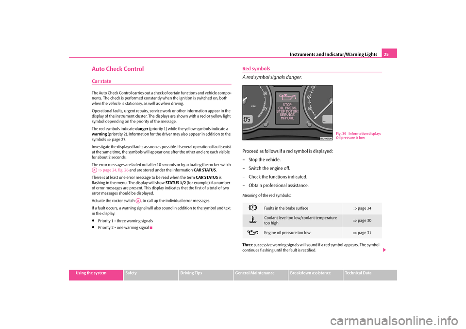
Red symbols A red symbol signals danger.Proceed as follows if a red symbol is displayed: – Stop the vehicle.– Switch the engine off. – Check the functions indicated. – Obtain professional assistance.Meaning of the red symbols: Three
successive warning signals will sound if a red symbol appears. The symbol
continues flashing until
the fault is rectified.
AA
AA
Faults in the brake surface
⇒page 34
Coolant level too low/coolant temperature too high
⇒ page 30
Engine oil pressure too low
⇒page 31
Fig. 29 Information display: Oil pressure is low
s2g8.b.book Page 25 Tuesday, April 7, 2009 8:53 AM
Page 27 of 224
Instruments and Indicator/Warning Lights
26
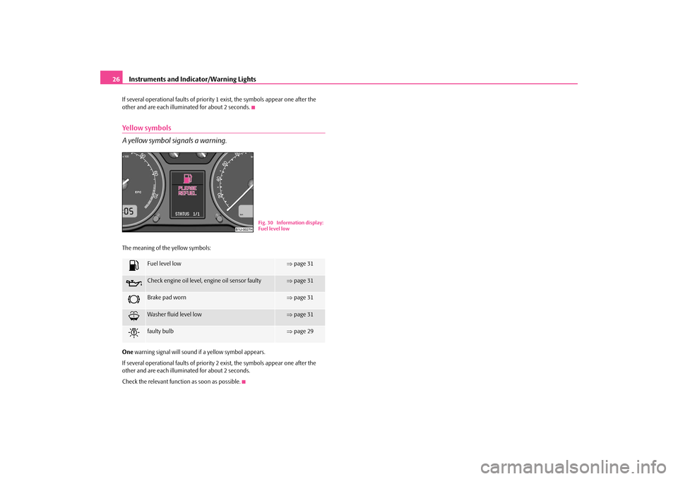
If several operational faults of priority 1 exist, the symbols appear one after the other and are each illuminated for about 2 seconds.Yellow symbols A yellow symbol signals a warning.The meaning of the yellow symbols: One
warning signal will sound if a yellow symbol appears.
If several operational faults of priority 2 exist, the symbols appear one after the other and are each illuminated for about 2 seconds. Check the relevant function as soon as possible.
Fuel level low
⇒ page 31
Check engine oil level, engine oil sensor faulty
⇒page 31
Brake pad worn
⇒page 31
Washer fluid level low
⇒page 31
faulty bulb
⇒page 29
Fig. 30 Information display: Fuel level low
s2g8.b.book Page 26 Tuesday, April 7, 2009 8:53 AM
Page 28 of 224
Instruments and Indicator/Warning Lights
27
Using the system
Safety
Driving Tips
General Maintenance
Breakdown assistance
Technical Data
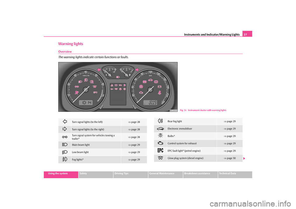
Warning lightsOverview The warning lights indicate certain functions or faults.
Fig. 31 Instrument cluster with warning lights
Turn signal lights (to the left)
⇒ page 28
Turn signal lights (to the right)
⇒page 28
Turn signal system fo
r vehicles towing a
trailer*
⇒ page 28
Main beam light
⇒page 29
Low beam light
⇒page 29
Fog lights*
⇒page 29
Rear fog light
⇒page 29
Electronic immobiliser
⇒page 29
Bulbs*
⇒page 29
Control system for exhaust
⇒page 29
EPC fault light* (petrol engine)
⇒page 29
Glow plug system (diesel engine)
⇒page 30
s2g8.b.book Page 27 Tuesday, April 7, 2009 8:53 AM
Page 29 of 224
Instruments and Indicator/Warning Lights
28
WARNING
•
If you do not pay attention to the wa
rning lights coming on and the corre-
sponding descriptions and warning notes, this may result in severe body injuries or major vehicle damage.•
The engine compartment of your car is
a hazardous area. There is a risk
of injuries, scalding, accidents and
fire when working in the engine
compartment, e.g. inspecting and replenis
hing oil and other fluids. It is also
essential to obse
rve all warnings
⇒page 160.
Note
•
Arrangement of the indicator lights depends on the model and model version.
The symbols shown in the following function
al description are to be found as indi-
cator lights in the instrument cluster.•
Operational faults are shown in the inst
rument cluster as red symbols (priority
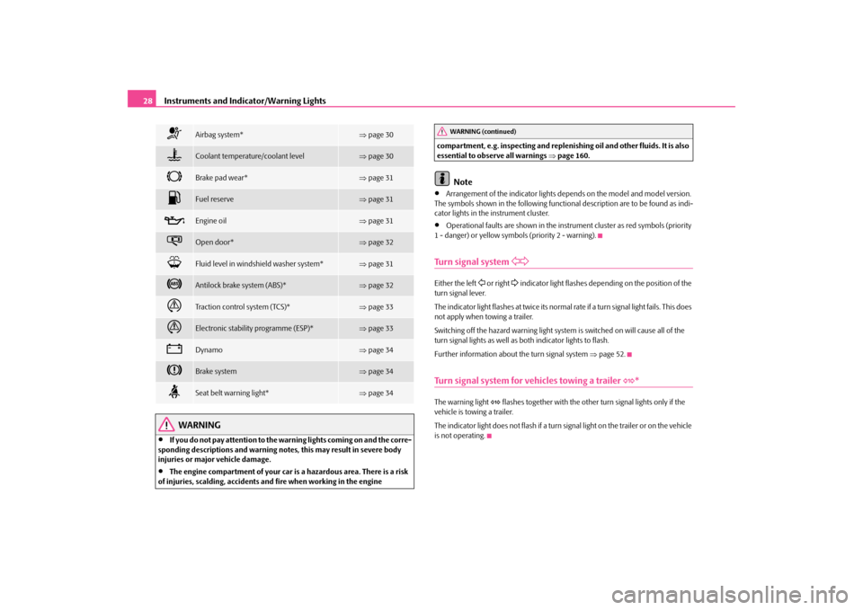
1 - danger) or yellow symbols (priority 2 - warning).Turn signal system
Either the left
or right
indicator light flashes depending on the position of the
turn signal lever. The indicator light flashes at twice its normal rate if a turn signal light fails. This does not apply when towing a trailer. Switching off the hazard warning light system is switched on will cause all of the turn signal lights as well as both indicator lights to flash. Further information about the turn signal system
⇒page 52.
Turn signal system for vehicles towing a trailer
*
The warning light
flashes together with the other turn signal lights only if the
vehicle is towing a trailer. The indicator light does not flash if a turn si
gnal light on the trailer or on the vehicle
is not operating.
Airbag system*
⇒ page 30
Coolant temperature/coolant level
⇒page 30
Brake pad wear*
⇒page 31
Fuel reserve
⇒page 31
Engine oil
⇒page 31
Open door*
⇒page 32
Fluid level in windshield washer system*
⇒page 31
Antilock brake system (ABS)*
⇒page 32
Traction control system (TCS)*
⇒page 33
Electronic stability programme (ESP)*
⇒page 33
Dynamo
⇒page 34
Brake system
⇒page 34
Seat belt warning light*
⇒page 34
WARNING (continued)
s2g8.b.book Page 28 Tuesday, April 7, 2009 8:53 AM
Page 30 of 224
Instruments and Indicator/Warning Lights
29
Using the system
Safety
Driving Tips
General Maintenance
Breakdown assistance
Technical Data
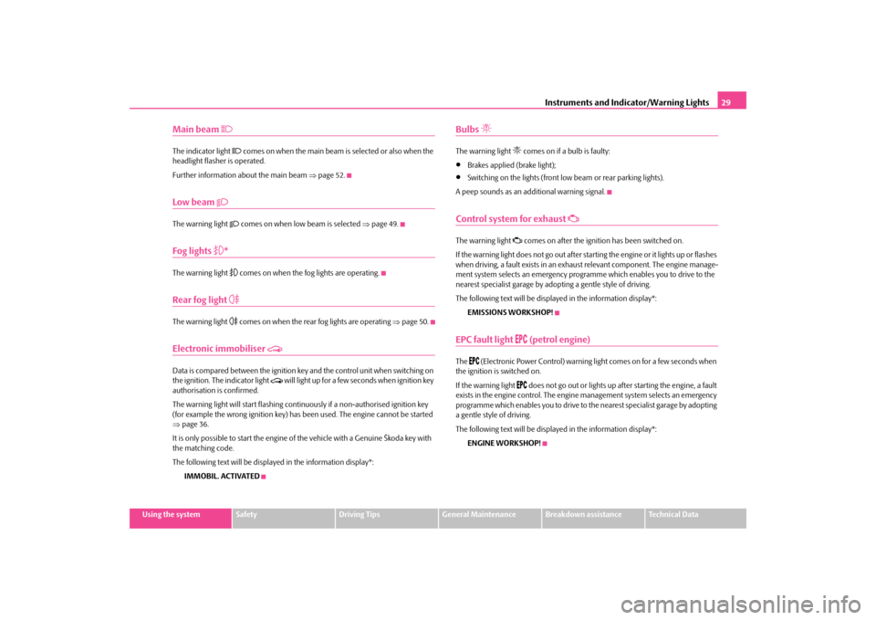
Main beam
The indicator light
comes on when the main beam is selected or also when the
headlight flasher is operated. Further information about the main beam
⇒page 52.
Low beam
The warning light
comes on when low beam is selected
⇒page 49.
Fog lights
*
The warning light
comes on when the fog lights are operating.
Rear fog light
The warning light
comes on when the rear fog lights are operating
⇒page 50.
Electronic immobiliser
Data is compared between the ignition ke
y and the control unit when switching on
the ignition. The indicator light
will light up for a few seconds when ignition key
authorisation is confirmed. The warning light will start flashing conti
nuously if a non-authorised ignition key
(for example the wrong ignition key) has
been used. The engine cannot be started
⇒ page 36. It is only possible to start the engine of
the vehicle with a Genuine Škoda key with
the matching code. The following text will be displayed in the information display*:
IMMOBIL. ACTIVATED
Bulbs
The warning light
comes on if a bulb is faulty:
•
Brakes applied (brake light);
•
Switching on the lights (front low beam or rear parking lights).
A peep sounds as an additional warning signal.Control system for exhaust
The warning light
comes on after the ignition has been switched on.
If the warning light does not go
out after starting the engine
or it lights up or flashes
when driving, a fault exists in an exhaus
t relevant component. The engine manage-
ment system selects an emergency programme which enables you to drive to the nearest specialist garage by adopting a gentle style of driving. The following text will be displayed in the information display*:
EMISSIONS WORKSHOP!
EPC fault light
(petrol engine)
The
(Electronic Power Control) warning light comes on for a few seconds when
the ignition is switched on. If the warning light
does not go out or lights up
after starting the engine, a fault
exists in the engine control. The engine management system selects an emergency programme which enables you to drive to the nearest specialist garage by adopting a gentle style of driving. The following text will be displayed in the information display*:
ENGINE WORKSHOP!
s2g8.b.book Page 29 Tuesday, April 7, 2009 8:53 AM