tow SKODA OCTAVIA TOUR 2009 1.G / (1U) Owner's Manual
[x] Cancel search | Manufacturer: SKODA, Model Year: 2009, Model line: OCTAVIA TOUR, Model: SKODA OCTAVIA TOUR 2009 1.G / (1U)Pages: 224, PDF Size: 13.53 MB
Page 5 of 224
Contents
4Driving Tips
. . . . . . . . . . . . . . . . . . . . . . . . . . . . . .
Intelligent Technology
. . . . . . . . . . . . . . . . . . . . . . . .
Electronic stability programme (ESP)* . . . . . . . . . . Brakes . . . . . . . . . . . . . . . . . . . . . . . . . . . . . . . . . . . . . . . Brake booster . . . . . . . . . . . . . . . . . . . . . . . . . . . . . . . . Antilock brake system (ABS)* . . . . . . . . . . . . . . . . . . Brake Assist* . . . . . . . . . . . . . . . . . . . . . . . . . . . . . . . . . Driving and the Environment
. . . . . . . . . . . . . . . . .
The first 1 500 kilometres and then afterwards . . Catalytic converter . . . . . . . . . . . . . . . . . . . . . . . . . . . . Driving in an economical and environmentally conscious manner . . . . . . . . . . . . . . . . . . . . . . . . . . . . Environmental compatibility . . . . . . . . . . . . . . . . . . . Motoring abroad . . . . . . . . . . . . . . . . . . . . . . . . . . . . . Avoiding damage to your vehicle . . . . . . . . . . . . . . To w i n g a t r a i l e r
. . . . . . . . . . . . . . . . . . . . . . . . . . . . . . . .
Towing a trailer . . . . . . . . . . . . . . . . . . . . . . . . . . . . . . . Detachable towing device* . . . . . . . . . . . . . . . . . . . . General Maintenance
. . . . . . . . . . . . . . .
Taking care of your ve
hicle and cleaning the
vehicle
. . . . . . . . . . . . . . . . . . . . . . . . . . . . . . . . . . . . . . . . .
General . . . . . . . . . . . . . . . . . . . . . . . . . . . . . . . . . . . . . . Care of the exterior of vehicle . . . . . . . . . . . . . . . . . . Care of the interior of vehicle . . . . . . . . . . . . . . . . . . Fuel
. . . . . . . . . . . . . . . . . . . . . . . . . . . . . . . . . . . . . . . . . . . . Petrol . . . . . . . . . . . . . . . . . . . . . . . . . . . . . . . . . . . . . . . . Diesel . . . . . . . . . . . . . . . . . . . . . . . . . . . . . . . . . . . . . . . Refuelling . . . . . . . . . . . . . . . . . . . . . . . . . . . . . . . . . . . . Emergency release of fuel filler flap . . . . . . . . . . . . Inspecting and replenishing
. . . . . . . . . . . . . . . . . .
Engine compartment . . . . . . . . . . . . . . . . . . . . . . . . . Engine oil . . . . . . . . . . . . . . . . . . . . . . . . . . . . . . . . . . . . Cooling system . . . . . . . . . . . . . . . . . . . . . . . . . . . . . . . Brake fluid . . . . . . . . . . . . . . . . . . . . . . . . . . . . . . . . . . .
Battery . . . . . . . . . . . . . . . . . . . . . . . . . . . . . . . . . . . . . . . Windshield washer system . . . . . . . . . . . . . . . . . . . .Wheels and Tyres
. . . . . . . . . . . . . . . . . . . . . . . . . . . . . .
Wheels . . . . . . . . . . . . . . . . . . . . . . . . . . . . . . . . . . . . . .Accessories, changes and replacement of partsAccessories and replacement parts . . . . . . . . . . . . . Technical changes . . . . . . . . . . . . . . . . . . . . . . . . . . . .Vehicles of the group N1 . . . . . . . . . . . . . . . . . . . . . .Breakdown assistance
. . . . . . . . . . . . . .
Breakdown assistance
. . . . . . . . . . . . . . . . . . . . . . . .
First-aid box*, Warning triangle* and bulb set* . . Fire extinguisher* . . . . . . . . . . . . . . . . . . . . . . . . . . . . .Vehicle tool kit . . . . . . . . . . . . . . . . . . . . . . . . . . . . . . . .Spray for repairing a tyre* . . . . . . . . . . . . . . . . . . . . .Tyre repair kit . . . . . . . . . . . . . . . . . . . . . . . . . . . . . . . . .Spare wheel* . . . . . . . . . . . . . . . . . . . . . . . . . . . . . . . . .Changing a wheel . . . . . . . . . . . . . . . . . . . . . . . . . . . . .Jump-starting . . . . . . . . . . . . . . . . . . . . . . . . . . . . . . . .Tow-starting and towing vehicle . . . . . . . . . . . . . . .Fuses and light bulbs
. . . . . . . . . . . . . . . . . . . . . . . . . .
Electric fuses . . . . . . . . . . . . . . . . . . . . . . . . . . . . . . . . . Bulbs . . . . . . . . . . . . . . . . . . . . . . . . . . . . . . . . . . . . . . . .Technical Data
. . . . . . . . . . . . . . . . . . . . . . . . . .
Technical Data
. . . . . . . . . . . . . . . . . . . . . . . . . . . . . . . . .
General information . . . . . . . . . . . . . . . . . . . . . . . . . . Used abbreviations . . . . . . . . . . . . . . . . . . . . . . . . . . .Performances . . . . . . . . . . . . . . . . . . . . . . . . . . . . . . . .Weight . . . . . . . . . . . . . . . . . . . . . . . . . . . . . . . . . . . . . . .Identification details . . . . . . . . . . . . . . . . . . . . . . . . . .Fuel consumption according to the regulations (99/100/EU) . . . . . . . . . . . . . . . . . . . . . . . . . . . . . . . . . . Dimensions . . . . . . . . . . . . . . . . . . . . . . . . . . . . . . . . . .1.4 ltr./55 kW - EU4 . . . . . . . . . . . . . . . . . . . . . . . . . . .1.6 ltr./75 kW - EU4/EU2 DDK . . . . . . . . . . . . . . . . . .
1.8 ltr./110 kW - EU4/EU3D . . . . . . . . . . . . . . . . . . . . 1.9 ltr./66 kW TDI - EU3 . . . . . . . . . . . . . . . . . . . . . . . .1.9 ltr./74 kW TDI PD - EU4 . . . . . . . . . . . . . . . . . . . .Octavia - Vehicles of the group N1 . . . . . . . . . . . . . .Octavia Combi - Vehicles of the group N1 . . . . . . .Index
. . . . . . . . . . . . . . . . . . . . . . . . . . . . . . . . . . . . . . . .
131 131 131 133134135135 137 137 138 138 142142143 144 144 146 147 147 147 147152 155 155 155156157 159 159 162165167
168 172 173 173 179 179 179179 181 181 181 181182182182183183188189 192 192 195 201 201 201 201201201201 202 203204206
208 210 212214214 215
s2g8.b.book Page 4 Tuesday, April 7, 2009 8:53 AM
Page 28 of 224
Instruments and Indicator/Warning Lights
27
Using the system
Safety
Driving Tips
General Maintenance
Breakdown assistance
Technical Data
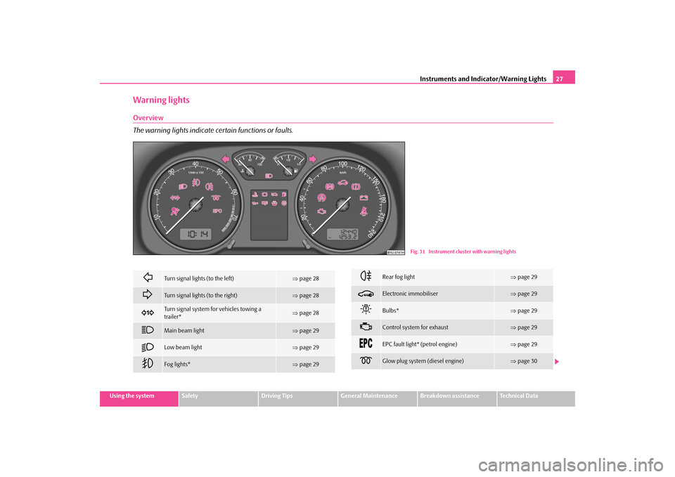
Warning lightsOverview The warning lights indicate certain functions or faults.
Fig. 31 Instrument cluster with warning lights
Turn signal lights (to the left)
⇒ page 28
Turn signal lights (to the right)
⇒page 28
Turn signal system fo
r vehicles towing a
trailer*
⇒ page 28
Main beam light
⇒page 29
Low beam light
⇒page 29
Fog lights*
⇒page 29
Rear fog light
⇒page 29
Electronic immobiliser
⇒page 29
Bulbs*
⇒page 29
Control system for exhaust
⇒page 29
EPC fault light* (petrol engine)
⇒page 29
Glow plug system (diesel engine)
⇒page 30
s2g8.b.book Page 27 Tuesday, April 7, 2009 8:53 AM
Page 29 of 224
Instruments and Indicator/Warning Lights
28
WARNING
•
If you do not pay attention to the wa
rning lights coming on and the corre-
sponding descriptions and warning notes, this may result in severe body injuries or major vehicle damage.•
The engine compartment of your car is
a hazardous area. There is a risk
of injuries, scalding, accidents and
fire when working in the engine
compartment, e.g. inspecting and replenis
hing oil and other fluids. It is also
essential to obse
rve all warnings
⇒page 160.
Note
•
Arrangement of the indicator lights depends on the model and model version.
The symbols shown in the following function
al description are to be found as indi-
cator lights in the instrument cluster.•
Operational faults are shown in the inst
rument cluster as red symbols (priority
1 - danger) or yellow symbols (priority 2 - warning).Turn signal system
Either the left
or right
indicator light flashes depending on the position of the
turn signal lever. The indicator light flashes at twice its normal rate if a turn signal light fails. This does not apply when towing a trailer. Switching off the hazard warning light system is switched on will cause all of the turn signal lights as well as both indicator lights to flash. Further information about the turn signal system
⇒page 52.
Turn signal system for vehicles towing a trailer
*
The warning light
flashes together with the other turn signal lights only if the
vehicle is towing a trailer. The indicator light does not flash if a turn si
gnal light on the trailer or on the vehicle
is not operating.
Airbag system*
⇒ page 30
Coolant temperature/coolant level
⇒page 30
Brake pad wear*
⇒page 31
Fuel reserve
⇒page 31
Engine oil
⇒page 31
Open door*
⇒page 32
Fluid level in windshield washer system*
⇒page 31
Antilock brake system (ABS)*
⇒page 32
Traction control system (TCS)*
⇒page 33
Electronic stability programme (ESP)*
⇒page 33
Dynamo
⇒page 34
Brake system
⇒page 34
Seat belt warning light*
⇒page 34
WARNING (continued)
s2g8.b.book Page 28 Tuesday, April 7, 2009 8:53 AM
Page 51 of 224
Lights and Visibility
50
•
The switching on of the described lights
should only be undertaken in accord-
ance with the legal requirements.•
If a fault occurs in the light switch
, the low beam comes on automatically
•
In the event of cool or humid weather co
nditions, the headligh
ts can be misted
up from inside.
− The temperature difference between interior and external area of the head- light lenses is decisive. − When the driving lights are switched on
, the light outlet surfaces are free
from mist after a short period. The headlight lenses can possibly mist up at the border areas. − It also concerns reverse light and turn signal lights. − This mist has no influence on th
e life of the lighting system.
Fog lights*
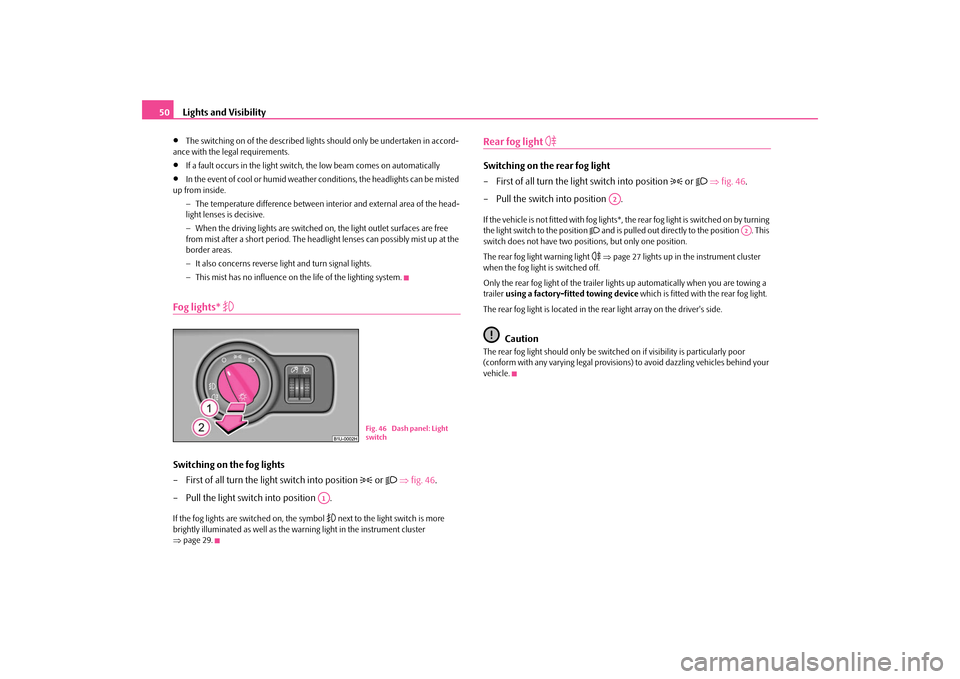
Switching on the fog lights – First of all turn the light switch into position
or
⇒
fig. 46
.
– Pull the light switch into position .If the fog lights are switched on, the symbol
next to the light switch is more
brightly illuminated as well as the warning light in the instrument cluster ⇒ page 29.
Rear fog light
Switching on the rear fog light – First of all turn the light switch into position
or
⇒
fig. 46
.
– Pull the switch into position .If the vehicle is not fitted with fog lights*,
the rear fog light is switched on by turning
the light switch to the position
and is pulled out directly to the position . This
switch does not have two positions, but only one position. The rear fog light warning light
⇒page 27 lights up in the instrument cluster
when the fog light is switched off. Only the rear fog light of the trailer ligh
ts up automatically when you are towing a
trailer
using a factory-fitted towing device
which is fitted with the rear fog light.
The rear fog light is located in the rear light array on the driver's side.
Caution
The rear fog light should only be switched
on if visibility is particularly poor
(conform with any varying legal provisions) to avoid dazzling vehicles behind your vehicle.
Fig. 46 Dash panel: Light switch
A1
A2
A2
s2g8.b.book Page 50 Tuesday, April 7, 2009 8:53 AM
Page 56 of 224
Lights and Visibility
55
Using the system
Safety
Driving Tips
General Maintenance
Breakdown assistance
Technical Data
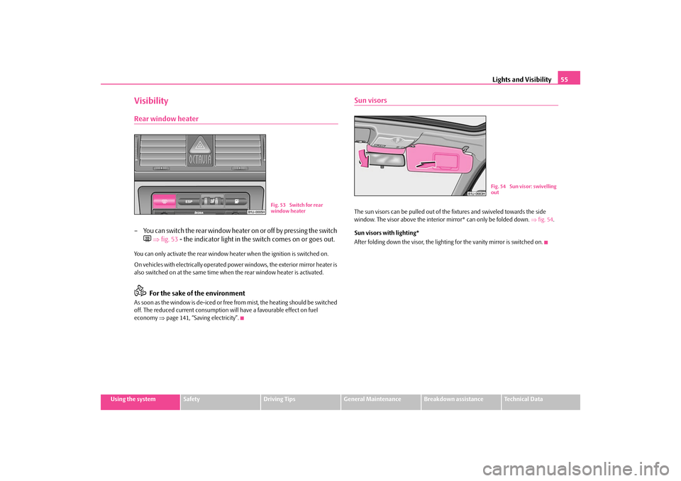
VisibilityRear window heater– You can switch the rear window heater on or off by pressing the switch
⇒
fig. 53
- the indicator light in the
switch comes on or goes out.
You can only activate the rear window he
ater when the ignition is switched on.
On vehicles with electrically operated power windows, the exterior mirror heater is also switched on at the same time when
the rear window heater is activated.
For the sake of the environment
As soon as the window is de-iced or free from mist, the heating should be switched off. The reduced current consumption will have a favourable effect on fuel economy
⇒page 141, “Saving electricity”.
Sun visorsThe sun visors can be pulled out of the fixtures and swiveled towards the side window. The visor above the interior mirror* can only be folded down.
⇒fig. 54
.
Sun visors with lighting* After folding down the visor, the lighting for the vanity mirror is switched on.
Fig. 53 Switch for rear window heater
Fig. 54 Sun visor: swivelling out
s2g8.b.book Page 55 Tuesday, April 7, 2009 8:53 AM
Page 57 of 224
Lights and Visibility
56
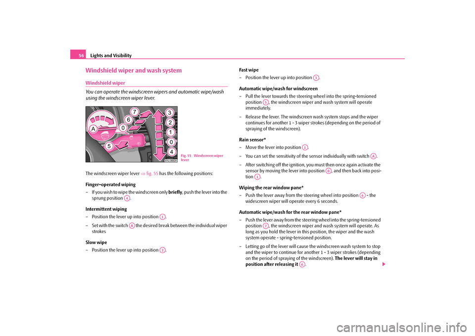
Windshield wiper and wash systemWindshield wiper You can operate the windscreen wipers and automatic wipe/wash using the windscreen wiper lever.The windscreen wiper lever
⇒
fig. 55
has the following positions:
Finger-operated wiping – If you wish to wipe the windscreen only
briefly
, push the lever into the
sprung position .
Intermittent wiping – Position the lever up into position . – Set with the switch the desired break between the individual wiper
strokes
Slow wipe – Position the lever up into position .
Fast wipe – Position the lever up into position . Automatic wipe/wash for windscreen – Pull the lever towards the steering wheel into the spring-tensioned
position , the windscreen wiper and wash system will operate immediately.
– Release the lever. The windscreen wash system stops and the wiper
continues for another 1 - 3 wiper strokes (depending on the period of spraying of the windscreen).
Rain sensor* – Move the lever into position . – You can set the sensitivity of the
sensor individually with switch .
– After switching off the ignition, you must then once again activate the
sensor by moving the lever into po
sition , and then back into posi-
tion .
Wiping the rear window pane* – Push the lever away from the steering wheel into position - the
widescreen wiper will operate every 6 seconds.
Automatic wipe/wash for the rear window pane* – Push the lever away from the steering wheel into the spring-tensioned
position , the windscreen wiper and wash system will operate. As long as you hold the lever in this position, the wiper and the wash system operate - spring-tensioned position.
– Letting go of the lever will cause th
e windscreen wash system to stop
and the wiper to continue for anothe
r 1 - 3 wiper strokes (depending
on the period of spraying of the windscreen).
The lever will stay in
position after releasing it
.
Fig. 55 Windscreen wiper lever
A4
A1
AA
A2
A3
A5
A1
AA
A0
A1
A6
A7
A6
s2g8.b.book Page 56 Tuesday, April 7, 2009 8:53 AM
Page 70 of 224
Seats and Storage
69
Using the system
Safety
Driving Tips
General Maintenance
Breakdown assistance
Technical Data
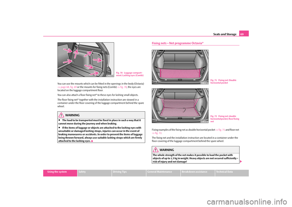
You can use the mounts which can be fitted
in the openings in the body (Octavia)
⇒ page 68, fig. 69
or the mounts for fixing nets (Combi)
⇒fig. 70
, the eyes are
located on the luggage compartment floor. You can also attach a floor fixing net*
to these eyes for lashing small objects.
The floor fixing net* together with the
installation instruction are stowed in a
container under the floor covering of the luggage compartment behind the spare wheel.
WARNING
•
The load to be transported must be fi
xed in place in such a way that it
cannot move during the journey and when braking.•
If the items of luggage or objects are
attached to the lashing eyes with
unsuitable or damaged lashing straps,
injuries can occur in the event of
braking manoeuvres or ac
cidents. In order to prevent the items of luggage
being thrown forward, always use suitable lashing straps which are firmly attached to the lashing eyes.
Fixing nets - Net programme Octavia*Fixing examples of the fixing ne
t as double horizontal pocket
⇒fig. 71
and floor net
⇒ fig. 72
.
The fixing net and the installation instru
ction are located in
a container under the
floor covering of the luggage compartment behind the spare wheel.
WARNING
The whole strength of the net makes it possible to load the pocket with objects of up to 1,5 kg in weight. Heavy objects are not secured sufficiently - risk of injury and net damage!
Fig. 70 Luggage compart- ment: Lashing eyes (Combi)
Fig. 71 Fixing net: Double horizontal pocketFig. 72 Fixing net: double horizontal pocket, floor fixing net
s2g8.b.book Page 69 Tuesday, April 7, 2009 8:53 AM
Page 72 of 224
Seats and Storage
71
Using the system
Safety
Driving Tips
General Maintenance
Breakdown assistance
Technical Data
Luggage compartment cover (Octavia) You can use the luggage compartment cover behind the head restraints for storing
light and soft items.
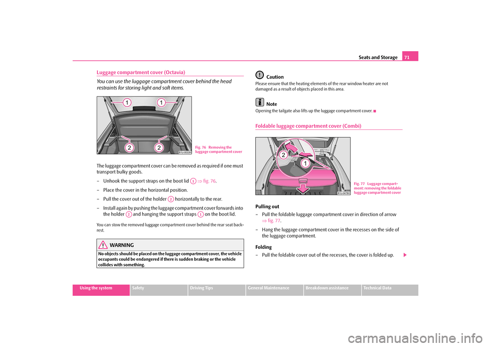
The luggage compartment cover can be
removed as required if one must
transport bulky goods. – Unhook the support stra
ps on the boot lid
⇒
fig. 76
.
– Place the cover in the horizontal position. – Pull the cover out of the holder horizontally to the rear.– Install again by pushing the luggage
compartment cover forwards into
the holder and hanging the suppo
rt straps on the boot lid.
You can stow the removed luggage compartment cover behind the rear seat back- rest.
WARNING
No objects should be placed on the
luggage compartment cover, the vehicle
occupants could be endangered if th
ere is sudden braking or the vehicle
collides with something.
Caution
Please ensure that the heating elements of the rear window heater are not damaged as a result of obje
cts placed in this area.
Note
Opening the tailgate also lifts up the luggage compartment cover.Foldable luggage compartment cover (Combi)Pulling out – Pull the foldable luggage compartment cover in direction of arrow
⇒
fig. 77
.
– Hang the luggage compartment cover in the recesses on the side of
the luggage compartment.
Folding – Pull the foldable cover out of the recesses, the cover is folded up.
Fig. 76 Removing the luggage compartment coverA1
A2
A2
A1
Fig. 77 Luggage compart-ment: removing the foldable luggage compartment cover
s2g8.b.book Page 71 Tuesday, April 7, 2009 8:53 AM
Page 74 of 224
Seats and Storage
73
Using the system
Safety
Driving Tips
General Maintenance
Breakdown assistance
Technical Data
– Fold open the loading floor. – Lock the loading floor by turning
the locking bolts by approx. 90°
to the right.
WARNING
Pay attention when installing that the
carrier rails and the variable loading
floor are correctly fixed, otherw
ise the occupant
s are at risk.
Divide the luggage compartmen
t with variable loading floor*
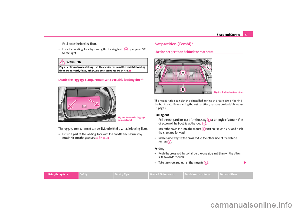
The luggage compartment can be divided with the variable loading floor. – Lift up a part of the loading floor with the handle and secure it by
moving it into the grooves
⇒
fig. 80
.
Net partition (Combi)*Use the net partition behind the rear seatsThe net partition can either be insta
lled behind the rear seats or behind
the front seats. Before using the net partition, remove the foldable cover ⇒
page 71.
Pulling out – Pull the net partition out of the hous
ing at an angle of about 45° in
direction of the boot lid at the loop .
– Insert the cross rod into the mount first on the one side and push
the cross rod forward.
– In the same way, fix the cross rod to the other side of the vehicle,
mount .
Folding – Push the cross rod first of all on the one side and then on the other
side towards the rear.
– Take the cross rod out of the mounts .
AA
Fig. 80 Divide the luggage compartment
Fig. 81 Pull out net partition
AB
AAAC
AC
AC
s2g8.b.book Page 73 Tuesday, April 7, 2009 8:53 AM
Page 75 of 224
Seats and Storage
74
– Roll the net partition at an angle of
approx. 45° towards the boot lid in
the housing ,
so that it does not roll up automatically
.
WARNING
•
First check for yourself that the cros
s road is inserted into the mounts
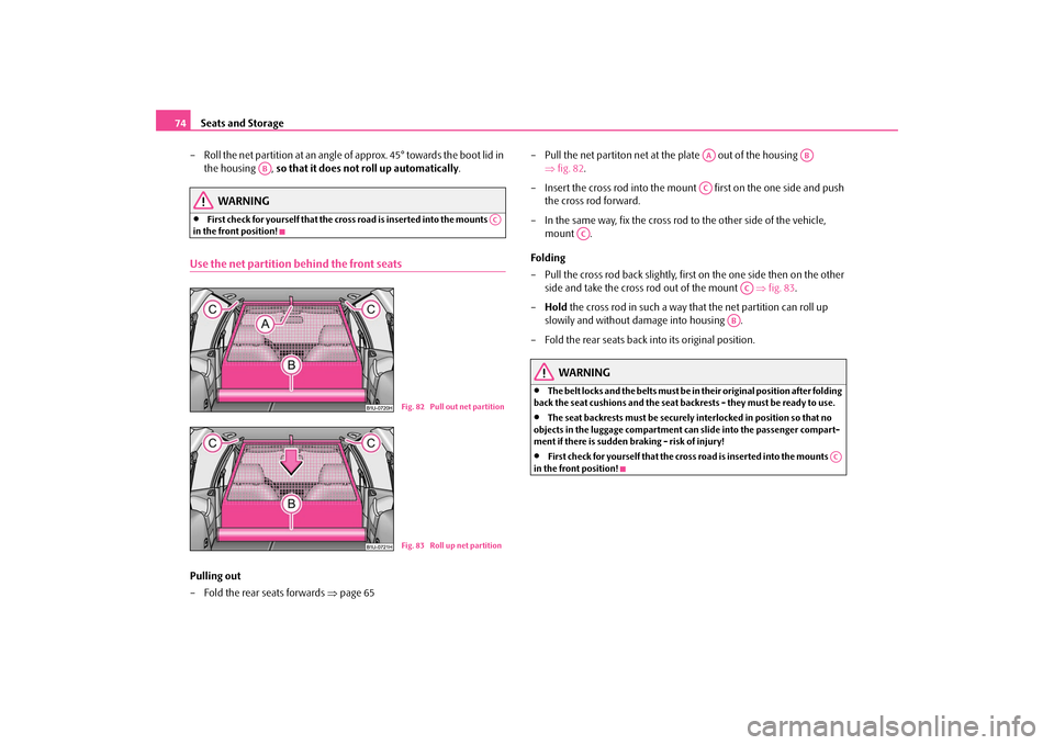
in the front position!Use the net partition behind the front seatsPulling out – Fold the rear seats forwards
⇒
page 65
– Pull the net partiton net at the plate out of the housing
⇒
fig. 82
.
– Insert the cross rod into the mount first on the one side and push
the cross rod forward.
– In the same way, fix the cross rod to the other side of the vehicle,
mount .
Folding – Pull the cross rod back slightly, first on the one side then on the other
side and take the cross rod out of the mount
⇒
fig. 83
.
–
Hold
the cross rod in such a way that the net partition can roll up
slowily and without damage into housing .
– Fold the rear seats back into its original position.
WARNING
•
The belt locks and the belts must be in their original position after folding
back the seat cushions and the seat backrests - they must be ready to use.•
The seat backrests must be securely interlocked in position so that no
objects in the luggage compartment ca
n slide into the passenger compart-
ment if there is sudden braking - risk of injury!•
First check for yourself that the cross
road is inserted into the mounts
in the front position!
AB
AC
Fig. 82 Pull out net partitionFig. 83 Roll up net partition
AA
AB
AC
AC
AC
AB
AC
s2g8.b.book Page 74 Tuesday, April 7, 2009 8:53 AM