wheel SKODA OCTAVIA TOUR 2010 2.G / (1Z) Owner's Guide
[x] Cancel search | Manufacturer: SKODA, Model Year: 2010, Model line: OCTAVIA TOUR, Model: SKODA OCTAVIA TOUR 2010 2.G / (1Z)Pages: 199, PDF Size: 12.09 MB
Page 97 of 199

Airbag system
96
Apart from their normal protective function, a further task of the seat belts is to also
hold the driver and front passenger in a correct seated position in the event of a frontal
collision so as to enable the front ai rbags to offer the maximum protection.
You should therefore always fasten the seat be lts, not only because this is required by
law, but also for safety reasons and for your own protection page 89, “Why seat
belts?”.
Note
The dash panel must be replaced after the front passenger airbag has been
deployed.Function of the front airbags
Risk of injury to the head and ches t area is reduced by fully inflated
airbags.The airbag system is designed in such a way that the driver and the front passenger
airbag* are deployed in the event of a frontal collision of major severity.
In certain accident situ ations, the front, side and head airbag are deployed together.
If the airbags are deployed, the airbags are filled with a propellant gas and inflated in
front of the driver and front passenger fig. 96 . The airbags inflate in fractions of a
second and at a high speed in order to be able to offer that additional protection in the
event of an accident. The forward movement of the driver and of the front passenger
is cushioned when they make contact with the fully inflated airbag and the risk of injury
to head and chest is thus reduced. The specially developed airbag allows the gas
to flow out of the inflated airbag in a
controlled manner (depending on the load of the particular car occupant) in order to
cushion head and chest areas. The airbag then deflates subsequently to such an extent,
after an accident, to again provide a clear view forward.
A grey white, non harmful gas is released when airbag is inflated. This is perfectly
normal and is not an indicati on of a fire in the vehicle.
The airbag develops enormous forces when triggered, which can lead to injuries if the
sitting position or seated position is not correct page 96.
Important safety information regarding the front airbag system
Correct use of the airbag system cons iderably reduces the risk of injury!
WARNING
Never transport children on the front seat of a vehicle without using a
proper restraint system. If airbags are de ployed in the event of an accident, the
child might suffer severe or even fatal injuries!
For the driver and front passenger it is important to maintain a distance of
at least 25 cm from the steering wheel or dash panel fig. 97 . Not maintaining
this minimum distance will mean that the airbag system will not be able to
properly protect you - hazard! The front seats and the head restraints must
always also be correctly adjusted to match the body size of the occupant.
It is essential to always switch off th e front passenger airbag when attaching
a child safety seat on the front passenger seat where the child is seated with its
back facing in direction of travel (in some countries also when the child is facing
Fig. 96 Deployed front airbags
Fig. 97 Safe distance to steering wheel
s2bs.2.book Page 96 Monday, September 27, 2010 9:53 AM
Page 98 of 199

Airbag system97
Using the system
Safety
Driving Tips
General Maintenance
Breakdown assistance
Technical Data
the direction of travel)
page 101, “Deactivating an airbag”. If this is not done,
there is a risk of the child suffering seve re or even fatal injuries if the front
passenger airbag is deployed. The national legal provisions in certain countries
require that both the front, side and head airbags be deactivated. When trans-
porting a child on the front passenger se at, please comply with the appropriate
national legal provisions regarding the use of child safety seats.
There must not by any further persons, animals or objects positioned
between the front seated occupants and the deployment area of the airbag.
The steering wheel and the surface of the airbag module in the dash panel
on the passenger side must not be stuck onto, covered or modified in any other
way. These parts should only be cleaned with a dry cloth or a cloth moistened
with water. No objects such as cup holders, mobile phone mounts, etc. may be
attached to the covers of the airbag modules or be located within the imme-
diate area.
No modifications of any kind may be made to parts of the airbag system.
Any work on the airbag system includ ing installing and removing system
components because of other repair wo rk (e.g. removing the steering wheel)
must only be carried out by a specialist garage.
Never carry out changes on the front bumper or on the body.
Never place any objects on the surface of the front passenger airbag module
in the dash panel.
side airbags*Description of the side airbags
The side airbag together with the head airbag offers enhanced occu-
pant protection in the event of a side collision.The front side airbags are housed in the upholstery of the seat backrests of the front
seats fig. 98 .
The side airbag system in combination with the three-point seat belts, offers additional
protection for the upper area of the body (chest, stomach and pelvis) of the occupants
of the vehicle in the event of severe side collisions page 98.
Apart from their normal protective function, a further task of the seat belts is to also
hold the occupants of the front or rear exterior seats in position so as to enable the side
airbag to offer the maximum protection in the event of a side collision.
You should therefore always fasten the seat belts, not only because this is required by
law, but also for safety reasons and for your own protection.
Each time the side airbags are deployed, th e head airbag* and the front belt tensioner
on the side of the car on which the collision occurs, are automatically deployed at the
same time in order to provide the occupant with enhanced protection.
WARNING (continued)
Fig. 98 Installation position of side
airbag in driver seat
s2bs.2.book Page 97 Monday, September 27, 2010 9:53 AM
Page 102 of 199
Airbag system101
Using the system
Safety
Driving Tips
General Maintenance
Breakdown assistance
Technical Data
being deployed. When the deployed head airbag is inflated, parts of the acces-
sories fitted may in certain circumstances be thrown into the interior of the car
and cause injuries to the occupants
page 157, “Accessories, changing and
replacing parts”.
Any work on the head airbag system including installing and removing
system components because of other repair work (e.g. removing headliner)
must only be carried out by a specialist garage.
Deactivating an airbagDeactivating airbags
If any airbags have been deactivated, switch them on again as soon as
possible so that they are able to again provide their proper protection.There is the technical means installed within your vehicle to switch off the front, side*
or head airbag* (take out of commission).
This is why you should have the deactivation of the airbags carried out by a specialist
garage.
On vehicles equipped with the switch for de activation of the airbags, you can deacti-
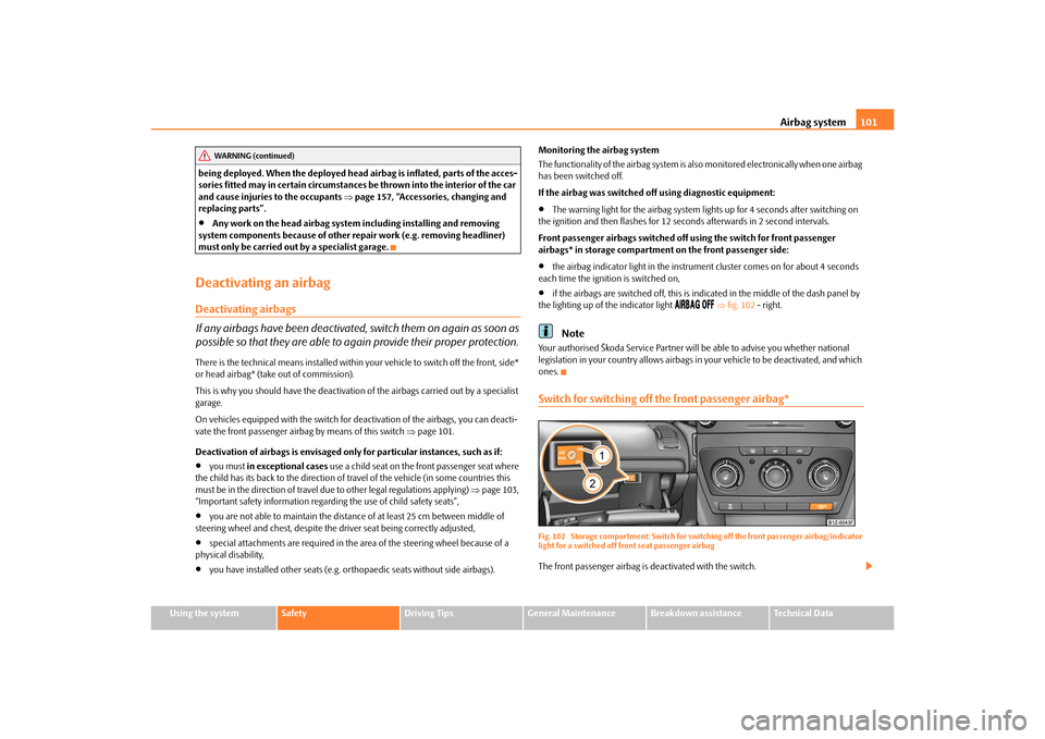
vate the front passenger airbag by means of this switch page 101.
Deactivation of airbags is envisaged only for particular instances, such as if:
you must in exceptional cases use a child seat on the front passenger seat where
the child has its back to the direction of tr avel of the vehicle (in some countries this
must be in the direction of travel due to other legal regulations applying) page 103,
“Important safety information regarding the use of child safety seats”,
you are not able to maintain the distan ce of at least 25 cm between middle of
steering wheel and chest, despite the driver seat being correctly adjusted,
special attachments are required in the ar ea of the steering wheel because of a
physical disability,
you have installed other seats (e.g. orthopaedic seats without side airbags). Monitoring the airbag system
The functionality of the airbag system is al
so monitored electronically when one airbag
has been switched off.
If the airbag was switched off using diagnostic equipment:
The warning light for the airbag system li ghts up for 4 seconds after switching on
the ignition and then flashes for 12 seconds afterwards in 2 second intervals.
Front passenger airbags switched off using the switch for front passenger
airbags* in storage compartmen t on the front passenger side:
the airbag indicator light in the instrume nt cluster comes on for about 4 seconds
each time the igniti on is switched on,
if the airbags are switched off, this is in dicated in the middle of the dash panel by
the lighting up of the indicator light
fig. 102 - right.
Note
Your authorised Škoda Service Partner will be able to advise you whether national
legislation in your country allows airbags in your vehicle to be deactivated, and which
ones.Switch for switching off the front passenger airbag*Fig. 102 Storage compartment: Switch for swit ching off the front passenger airbag/indicator
light for a switched off front seat passenger airbagThe front passenger airbag is deactivated with the switch.
WARNING (continued)
s2bs.2.book Page 101 Monday, September 27, 2010 9:53 AM
Page 112 of 199
Intelligent Technology111
Using the system
Safety
Driving Tips
General Maintenance
Breakdown assistance
Technical Data
Driving TipsIntelligent TechnologyElectronic stability programme (ESP)*GeneralThe ESP aids you in maintaining control of your vehicle in situations in which the
vehicle is driving at its dynamic limits, such as entering a curve fast. The risk of skidding
is reduced and your vehicle thus offers greater driving stability depending on the
conditions of the road surface. The system operates at all speeds.
The following systems are integrated into the electronic stability programme:
Electronic Differential Lock (EDL),
Traction control system (TCS),
active driver-steering recommendation (DSR),
Antilock brake system (ABS),
Brake Assist,
Uphill-Start off-Assist.
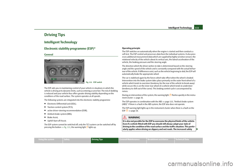
The ESP system cannot be switched off, only the TCS system can be switched off by
pressing the button fig. 111 , the warning light
lights up. Operating principle
The ESP switches on automatically when the engine is started and then conducts a
self-test. The ESP control unit processes data from the individual systems. It also proc-
esses additional measurement data which are supplied by highly sensitive sensors: the
rotational velocity of the vehicle about its ve
rtical axis, the lateral acceleration of the
vehicle, the braking pressure and the steering angle.
The direction which the driver wishes to take is determined based on the steering
angle and the speed of the vehicle and is co nstantly compared with the actual behav-
iour of the vehicle. If differences exist, such as the vehi cle beginning to skid, the ESP will
automatically brake the appropriate wheel.
The car is stabilised again by the forces wh ich take effect when the wheel is braked.
Intervention into the brake system takes place primarily on the outer front wheel of a
vehicle which tends to oversteer (tendency for the rear of the vehicle to break away)
while occurs this is on the inner rear wh eel of a vehicle which tends to understeer
(tendency to shift out of the curve). This braking control cycle is accompanied by
noises.
During an intervention of the system, the warning light
flashes quickly in the instru-
ment cluster page 26.
The ESP operates in combination with the ABS page 115, “Antilock brake system
(ABS)”. If there is a fault in the ABS system, the ESP also does not operate.
The ESP warning light lights up in the instrument cluster when there is a fault on the
ESP
page 26.WARNING
It is also not possible for the ESP to overcome the physical limits of the vehicle.
Even if a vehicle fitted with ESP you should still always adapt your style of
driving to the condition of the road surfac e and the traffic situation. This partic-
ularly applies when driving on slippery and wet roads. The increased safety
Fig. 111 ESP switch
s2bs.2.book Page 111 Monday, September 27, 2010 9:53 AM
Page 113 of 199
Intelligent Technology
112
offered must not tempt you to take greater risks than otherwise - risk of an acci-
dent!
Note
All four wheels must be fitted with the same tyres in order to achieve problem-free
operation of the ESP. Differing rolling circum ferences of the tyres can lead to an unde-
sirable reduction in the engine output.
Changes to vehicle (e.g. on engine, on th e brakes, on chassis or another combina-
tion of tyres and wheels) can influence the function of the ESP page 157, “Accesso-
ries, changing and replacing parts”.
Electronic Differential Lock (EDL)*
The electronic differential lock prev ents an individual wheel from slip-
ping.Models fitted with ESP ar e equipped with electronic differential lock (EDL).
General
The EDL makes it much easier, and sometimes at all possible, to start off, accelerate
and climb a steep hill when the conditions of the road surface are unfavourable.
Operating principle
The EDL is activated automaticall y, that is without any action on the part of the driver.
It monitors the speeds of the driven wheels with the aid of the ABS sensors. Should
only one drive wheel begin spinning on a slippery surface there will be an appreciable
difference in the speed of the driven wheels. The EDL function brakes the slipping
wheel and the differential transmits a greate r driving force to the other driven wheel.
This control process is also accompanied by noises.
Overheating of the brakes
The EDL switches off automatica lly if unusually severe stresses exist in order to avoid
excessive heat generation in the disc brake on the wheel which is being braked. The
vehicle can continue to be driven and has the same characteristics as a vehicle not
fitted with EDL. The EDL switches on again automatically
as soon as the brake has cooled down.
WARNING
Carefully depress the accelerator when accelerating on uniformly slippery
road surfaces, such as ice and snow. Th e driven wheels might still spin despite
the EDL and affect the stability of the vehicle - risk of an accident!
You should always adapt your style of driving to the condition of road
surface and to the traffic situation even when your vehicle is fitted with EDL.
The increased safety offered must not tempt you to take greater risks than
otherwise - risk of an accident!Note
If the ABS or ESP warning light comes on, this may also indicate a fault in the EDL.
Please have the vehicle inspected as soon as possible by a specialist garage.
Changes to vehicle (e.g. on engine, on the brakes, on chassis or another combina-
tion of tyres and wheels) can influence the function of the EDL page 157, “Accesso-
ries, changing and replacing parts”.
Traction control system (TCS)
The traction control system prevents the driven wheels from spinning
when accelerating.
WARNING (continued)
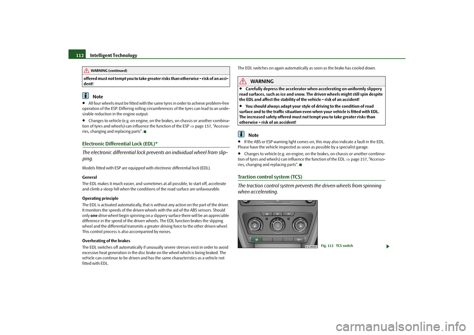
Fig. 112 TCS switch
s2bs.2.book Page 112 Monday, September 27, 2010 9:53 AM
Page 114 of 199

Intelligent Technology113
Using the system
Safety
Driving Tips
General Maintenance
Breakdown assistance
Technical Data
General
The TCS makes it much easier, and sometimes at
all possible, to start off, accelerate and
climb a steep hill when th e conditions of the road surface are unfavourable.
Operating principle
The TCS switches on automatically when th e engine is started and then conducts a
self-test. The system monitors the speeds of the driven wheels with the aid of the ABS
sensors. If the wheels are spinning, the force transmitted to the road surface is auto-
matically adapted by reducing the engine speed. The system operates at all speeds.
The TCS operates in combination with the ABS page 115, “Antilock brake system
(ABS)”. The TCS will not function if a fault exists in the ABS system.
The TCS warning light lights up in the instru ment cluster when there is a fault on the
TCS
page 26.
During an intervention of the system, the TCS warning light
flashes in the instru-
ment cluster page 26.
Switching off
You can switch the TCS off and on again as you wish by pressing the button
page 112, fig. 112 . The TCS warning light lights up in the instrument cluster when
the TCS is switched off
page 26.
The TCS should normally always be switched on. It may be good practice in certain
exceptional cases, such as when you wish to have wheel slip, to switch off the system.
Examples:
when driving with snow chains
when driving in deep snow or on a loose surface
when it is necessary to rock a vehicle when it has become stuck.
then you should switch on the TCS again.
WARNING
You should always adjust your style of driving to the conditions of the road
surface and the traffic situation. The increased safety offered must not tempt
you to take greater risks than otherwise - risk of an accident!
Note
All four wheels must be fitted with the same tyres in order to achieve problem-free
operation of the TCS. Differing rolling circumferences of the tyres can lead to an unde-
sirable reduction in the engine output.
Changes to vehicle (e.g. on engine, on the brakes, on chassis or another combina-
tion of tyres and wheels) can influence the function of the TCS page 157, “Accesso-
ries, changing and replacing parts”.
Active driver-steering recommendation (DSR)*Vehicles with ESP are equipped with active driver-steering recommendation (DSR).
This function indicates to the driver in crit ical situations a steering recommendation in
order to stabilise the vehicle. The active driver-steering recommendation is activated,
for example, on the right and left vehicle si de when braking sharply on different road
surfaces.
WARNING
Even with this function the vehicle cann ot steer itself! The driver is furthermore
responsible for the steering of the vehicle!BrakesWhat has a negative effect on braking efficiency?Wear-and-tear
Wear-and-tear to the brake pa ds is greatly dependent on the operating conditions of
the vehicle and your style of driving. Particularly if you drive a great deal in towns and
over short distances or if you adopt a sporty style of driving, it may be necessary to
have the thickness of the brake pads insp ected at a specialist garage between the
service inspections.
Wet roads or road salt
There may be a certain delay before the brakes take full effect un der certain conditions
such as when driving through water, during heavy rain showers or after the vehicle has
been washed in an automatic vehicle wash , since the brake discs and brake pads may
s2bs.2.book Page 113 Monday, September 27, 2010 9:53 AM
Page 115 of 199

Intelligent Technology
114
be moist or even have a coatin g of ice on them in winter. Yo u s h o u l d d r y t h e b r a k e s a s
soon as possible by applying and releasing the brakes several times.
There also may be a certain delay before the full braking efficiency is available when
driving on roads which have been treated with road salt if you have not used the brakes
for some considerable time beforehand. The layer of salt on the brake discs and brake
pads must first be rubbed off when you apply the brakes.
Corrosion
Corrosion on the brake discs and dirt on th e bake pads occur if the vehicle has been
parked for a long period an d if you do not make much use of the braking system.
We recommend cleaning the brak e discs by firmly applying the brakes at a fairly high
speed if you do not make much use of the braking system or if surface corrosion is
present .
Faults in the brake surface
If you notice that the braking distance ha s suddenly become longer and that the brake
pedal can be depressed further, it is possible that a brake circuit of the dual-circuit
brake system has failed. Drive, in such cases, to the nearest specialist garage without
delay in order to have the problem rectified. Drive at a reduced speed while on your
way to the dealer and adapt your style of driving to the higher brake pedal pressure
required.
Low brake fluid level
An insufficient level of brake fluid may result in problems in the brake system. The level
of the brake fluid is monitored electronically page 28, “Brake system ”.
WARNING
Only apply the brakes for the purpose of drying and cleaning the brake discs
if the traffic conditions permit this. Do not place any other road users in jeop-
ardy.
When retrospectively mounting a front spoiler, solid wheel hubs etc. one
must ensure that the air supply to the front wheel brakes is not reduced other-
wise the braking system could run too hot.
Allow for the fact that new brake pads do not achieve their full braking effi-
ciency until after the first 200 kilometres . New brake pads must be first “run in”
before they develop their optimal friction force. You can, however, compensate for this slightly reduced braking force by increasing the pressure on the brake
pedal. This guideline also applies to any new brake pads installed at a future
date.
Caution
Never allow the brakes to rub by applying sl
ight pressure if you do not wish to brake
the vehicle. This causes the br akes to overheat and can also result in a longer braking
distance and excessive wear.
Before negotiating a steep downhill section, reduce your speed, shift down into the
next lower gear. This enables you to make full use of the braking power of the vehicle
and reduces the strain on the brakes. Any additional braking should be done intermit-
tently, not continuously.Note
The brake light flashes automatically in case of an emergency braking at speeds greater
than 60 km/h or with the intervention of th e ABS, which lasts longer than 1.5 seconds.
After the speed was reduced below 10 km/h or the vehicle was stopped, the brake light
stops flashing and the hazard warning light system switches on. The hazard warning
light system is switched of f automatically after accelerating or driving off again.Brake boosterThe brake booster boosts the pressure whic h you generate with the brake pedal. The
necessary pressure is only genera ted when the engine is running.
WARNING
Never switch off the engine befo re the vehicle is stationary.
The brake booster only operates when the engine is running. Greater phys-
ical effort for braking is required when en gine is switched off. Because if you do
not stop as normal, this can cause an accident and severe injuries.WARNING (continued)
s2bs.2.book Page 114 Monday, September 27, 2010 9:53 AM
Page 116 of 199

Intelligent Technology115
Using the system
Safety
Driving Tips
General Maintenance
Breakdown assistance
Technical Data
Antilock brake system (ABS)ABS prevents the wheels locking when braking.General
The ABS contributes significantly to enhanc ing the active safety of your vehicle.
Compared to a vehicle not fitted with ABS, you are able to retain optimal steering
ability even during a full brake applicatio n on a slippery road surface because the
wheels do not lock up.
You must not expect, however, that the br aking distance will be shorter under all
circumstances as a result of the ABS. The braking distance for example on gravel and
fresh snow, when you should anyway be driving slowly and cautiously, will be longer.
Operating principle
The brake pressure will be reduced on a wheel which is rotating at a speed which is too
low for the speed of the vehicle and tending to lock. This control cycle is noticeable
from a pulsating movement of the brake pedal which is accompanied by noises.
This is consciously intended to provide the driver with the information that the wheels
are tending to lock (ABS control range) . You must always keep the brake pedal
depressed to enable the ABS to optimally control the brake application in this braking
range. Never interrupt the application of the brakes!
WARNING
The ABS can also not overcome the physical limits of your vehicle. Please do
not forget this, particularly when driving on icy or wet road surfaces. If the ABS
is operating within the control range, adapt your speed immediately to the
conditions of the road surface and the traffic situation. The increased safety
offered by the ABS must not tempt you to take greater risks than otherwise -
risk of an accident!
The normal braking system is still fully functional if there is an ABS fault.
Visit a specialist garage as quickly as poss ible and adjust your style of driving to
take account of the ABS fault in the meantime since you will not know the extent
of the fault and in how far the braking efficiency is affected.Note
A warning light comes on if a fault occurs in the ABS system
page 27.
Changes to vehicle (e.g. on engine, on the brakes, on chassis or another combina-
tion of tyres and wheels) can in fluence the function of the ABS page 157, “Accesso-
ries, changing and replacing parts”.
Brake Assist*During a severe brake application (e.g. if a hazard exists), the Brake Assist increases the
braking force and thus makes it possible to rapidly produce the pressure required in
the brake system.
The majority of drivers do a pply the brakes in good time in dangerous situations, but
do not depress the brake pedal with sufficient pressure. Consequently, it is not possible
for the vehicle to achieve its maximum deceleration and the vehicle covers a greater
distance than necessary.
The Brake Assist is activated by the very qu ick operation of the brake pedal. In such
cases, a much greater braking pressure exists than during a normal brake application.
This makes it possible, even with a relatively low resistance of the brake pedal, to
produce an adequate pressure in the brake system in the shortest possible time, which
is required for maximum deceleration of the car. You must apply the brake pedal firmly
and hold it in this position in order to ac hieve the shortest possible braking distance.
The Brake Assist is able to help you achi eve a shorter braking distance in emergency
situations by rapidly producing the pressure required in the brake system. It fully
exploits the attributes of the ABS. After you release the brake pedal, the function of the
Brake Assist is automatically switched off and the brakes operate in the normal way.
The Brake Assist is part of the ESP system. If a fault occurs in the ESP, the Brake Assist
function is also not available. Further information on the ESP page 111.
WARNING
The Brake Assist is also not able to overcome the physical limits of your
vehicle in terms of the braking distance required.
Adapt your speed to the conditions of the road surface and to the traffic situ-
ation.
The increased safety offered by the Brake Assist must not tempt you to take
a greater safety risk than otherwise.
s2bs.2.book Page 115 Monday, September 27, 2010 9:53 AM
Page 117 of 199

Intelligent Technology
116
Electromechanical power steeringThe power steering enables you to steer the vehicle with le ss physical force.
With the electromechanical power steering , the steering assist is automatically
adapted to the speed and to the steering angle.
It is still possible to fully steer the vehicle if the power steering fails or if the engine is
not running (vehicle being towed in). The only difference is that greater physical effort
is required.
If there is a fault in the power steering, the warning light
or lights up in the instru-
ment cluster page 24.
WARNING
Contact your specialist garage if the power steering is defective.Tyre inflation pressure-control system*The tyre inflation pressure-control system compares with the aid of the ABS sensors
the speed and also the rolling circumference of the individual wheels. If the rolling
circumference of a wheel is changed, the warning light
lights up in the instrument
cluster page 27 and an audible signal sounds. The rolling circumference of the tyre
can change if:
the tyre inflation pressure is too low,
the structure of the tyre is damaged,
the vehicle is loaded on one side,
the wheels of an axle are loaded heavily (e.g. when towing a trailer or when driving
uphill or downhill),
snow chains are mounted,
the temporary spare wheel is mounted,
one wheel per axle was changed.
Basic setting of tyre inflation pressure-control system
After changing the tyre inflation pressures, after changing one or several wheels, the
position of a wheel on the vehicle (e.g. ex changing the wheels between the axles) or
when the warning light lights up while drivin g, a basic setting of the system must be
carried out as follows.
Inflate all tyres to the specified inflation pressure page 151.
Switch on the ignition.
Press button fig. 113 for more than 2 seconds. While pressing the button,
the warning light
lights up. At the same time the memory of the system is erased
and the new calibration is started, which is confirmed with an audible signal and then
the warning light goes out.
If the warning light
does not go out after the basic setting, there is a fault in the
system. Have the vehicle inspected by your nearest specialist garage.
Warning light
lights up
I f t h e t y re i n f l a t i o n p re s s u re o f a t l e a s t o n e wheel is insufficiently inflated in comparison
to the stored basic va lue, the warning light
lights up.
Warning light
flashes
If the warning light flashes, there is a system fault. Have the vehicle inspected by your
nearest specialist garage.
WARNING
When the warning light
lights up, immediately reduce the speed and
avoid sudden steering and brake manoeuvr es. Please stop the vehicle without
delay at the nearest possible stop and in spect the tyres and their inflation pres-
sures.
Fig. 113 Button for setting the tyre
inflation pressure control value
s2bs.2.book Page 116 Monday, September 27, 2010 9:53 AM
Page 127 of 199
Towing a trailer
126
Further information on the towing device page 126.
Note
We recommend that you also have your vehicle inspected between service inter-
vals if you tow a trailer frequently.
The handbrake on the towing vehicle must be put on when coupling and decou-
pling the trailer.
Driving Tips
Particular caution is required when towing a trailer.– Do not, as far as possible, drive with your vehicle unladen and the trailer laden.
– Do not make full use of the legal maximum speeds. This applies in particular to downhill sections.
– Apply the brakes in good time.
– Keep a check on the coolant temperature gauge if the outside temperature is high.
Distribution of weight
The distribution of the weight is very poor if your vehicle is unladen and the trailer is
laden. Maintain a particularly low speed if you cannot avoid driving with this combina-
tion.
Driving speed
Do not drive faster than 80 km/hour for safety reasons. This also applies for countries
in which higher speeds are allowed.
The fact that the driving stability of the vehicle + trailer combination reduces with
increasing speed means that the legally allo wed speed should not be used when there
are unfavourable road, weather or wind cond itions, particularly near accident black
spots.
You must always reduce your speed immediat ely as soon as you detect even just the
slightest swaying of the trailer. On no account attempt to stop the trailer from
“swaying” by accelerating.
Apply the brakes in good time! If the trailer is fitted with a trailer brake, apply the
brakes gently at first and then brake firmly. This will avoid brake jolts resulting from the trailer wheels locking. Shift down gears in good time before negotiating a downhill
section to allow the engine
to also act as a brake.
Engine overheating
Please keep a check on the coolant temperature gauge if you have to negotiate a
lengthy slope in a low gear at a high engi ne speed when the outside temperature is
very high page 16, “Engine coolant temperature Display”.
If the needle of the coolant temperature gaug e moves into the right-hand area or even
the red area of the scale, reduce your speed immediately. Stop and switch off the
engine if the warning light
in the instrument cluster begins flashing. Wait a few
minutes and check the level of coolant in the coolant expansion bottle page 143,
“Inspecting the coolant level”.
Please refer to the following guidelines page 25, “Coolant temperature/coolant
level ”.
The coolant temperature can be reduced by switching on the heating.
Any increase in the cooling effect of the coolant fan through shifting down a gear and
increasing the engine speed is not possible since the fan speed is independent of the
engine speed. One should also not drop a gear for this reason when towing a trailer as
long as the engine can manage th e slope without any drop in speed.
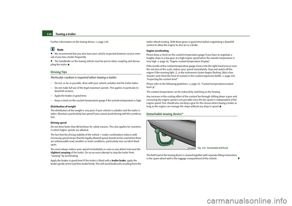
Detachable towing device*The ball head of the towing device is stowed together with separate fitting instructions
in the spare wheel well in the luggage compartment of the vehicle.
Fig. 118 Detachable ball head
s2bs.2.book Page 126 Monday, September 27, 2010 9:53 AM