wheel SKODA OCTAVIA TOUR 2010 2.G / (1Z) Service Manual
[x] Cancel search | Manufacturer: SKODA, Model Year: 2010, Model line: OCTAVIA TOUR, Model: SKODA OCTAVIA TOUR 2010 2.G / (1Z)Pages: 199, PDF Size: 12.09 MB
Page 162 of 199

Breakdown assistance161
Using the system
Safety
Driving Tips
General Maintenance
Breakdown assistance
Technical Data
The tyre repair kit is located in a textile bag. There is a velcro fastener on the underside
of the bag, with which the bag is attached to the floor covering of the luggage compart-
ment in such a way that the side of the
bag rests on the right side of the luggage
compartment and on the seat backrest.
Components of the tyre repair kitFig. 134 Components of the tyre repair kitThe tyre repair kit is made up of the following parts:
Screwdriver for removal and re-installation of valve core
Sticker with speed designation “max. 80 km/h”/“max. 50 mph”
Inflation hose with plug
Compressor
Air hose for the compressor
Tyre pressure checker
Air release valve
Stop button
Plug for 12V cigarette lighter socket
Bottle with sealant
Replacement valve core
Preparing to use the tyre repair kitBefore using the tyre repair kit, carry out the following preparatory work:
– If it is necessary to change a wheel, park the vehicle as far away as possible from
the traffic flow. The place you choose should be level.
–Have all the occupants get out. While changing a wheel, the occupants of the
vehicle should not stand on the ro ad (e.g. behind a crash barrier).
– Apply the handbrake firmly.
– Shift up into the 1st gear.
– If a trailer is coupled, uncouple it.
– Remove the tyre repair kit from the luggage compartment.
WARNING
If you find yourself in flowing traffic sw itch on the hazard warning lights system
and place the warning triangle on the side of the road at the prescribed distance
from your vehicle while observing all national legal provisions. In this way you
are protecting not only yourself but also other road users.Changing a wheelPreliminary workThe following steps should be carried ou t before actually changing the wheel.
– If it is necessary to change a wheel, park the vehicle as far away as possible from
the traffic flow. The place you choose should be level.
–Have all the occupants get out. While changing a wheel, the occupants of the
vehicle should not stand on the ro ad (e.g. behind a crash barrier).
– Apply the handbrake firmly.
– Shift up into the 1st gear.
– If a trailer is coupled, uncouple it.
A1A2A3A4A5A6A7A8A9A10A11
s2bs.2.book Page 161 Monday, September 27, 2010 9:53 AM
Page 163 of 199

Breakdown assistance
162
–Take the vehicle tool kit page 159 and the spare wheel* page 160 out of the
luggage compartment.
WARNING
If you find yourself in flowing traffic switch on the hazard warning lights
system and place the warning triangle on the side of the road at the prescribed
distance from your vehicle while observing all national legal provisions. In this
way you are protecting not only yourself but also other road users.
Never start the engine with the vehicle si tting on the raised jack - danger of
suffering injury.Caution
If you have to change a wheel on a slope first block the opposite wheel with a stone or
similar object in order to secure the vehicle from unexpec tedly rolling away.
Note
Comply with the national legal regulations.Changing a wheelAlways change a wheel on a level surface as far as possible.
– Take off the full wheel trim* page 163 or the caps page 163.
– In the case of light alloy wheels remove the wheel trim cap page 163.
– First of all slacken the safety wheel bo lt* and afterwards the other wheel bolts
page 164.
– Jack up the vehicle until the wheel to be changed is clear of the ground page 164.
– Unscrew the wheel bolts and place them on a clean surface (cloth, paper etc.).
– Take off the wheel.
– Fit on the spare wheel and ti ghten the wheel bolts slightly.
–Lower the car. – Tighten the wheel bolts firmly, alternatel
y and diagonally using the wheel wrench
(crosswise) and last the safety wheel bolt* page 164.
– Mount the full wheel trim/wheel trim cap or the caps.
Note
All bolts must be clean and must turn easily.
You must never grease or oil the wheel bolts!
When fitting on unidirectional tyres, ensu re that the tyres rotate in the correct
direction page 151.
Subsequent stepsAfter changing the wheel, you mu st perform the following steps.
– Stow and attach the replaced wheel in the spare wheel well.
– Stow the vehicle tool kit in the space provided.
– Check the tyre pressure on the spare wheel just mounted as soon as possible.
– Have the tightening torque of the wheel bolts checked with a torque wrench as
soon as possible. Steel and light alloy wheels must be tightened to a tightening
torque of 120 Nm.
– Change the damaged wheel or consult a sp ecialist garage about possibilities for
getting repairs done.
WARNING
It is necessary to observe the guidelines given on page 153 if the vehicle is
subsequently fitted with tyres which are di fferent to those it was fitted with at
the works.
Note
If you find, when changing the wheel, that the wheel bolts are corroded and diffi-
cult to turn, the bolts must be replaced before checking the tightening torque.
Drive cautiously and only at a moderate speed to a workshop where the tightening
torque can be checked.
s2bs.2.book Page 162 Monday, September 27, 2010 9:53 AM
Page 164 of 199

Breakdown assistance163
Using the system
Safety
Driving Tips
General Maintenance
Breakdown assistance
Technical Data
Full wheel trim*Pulling off– Hook the clamp found in the vehicle tool kit into the reinforced edge of the full
wheel trim.
– Push the wheel wrench* through the clamp, support it at the tyre and pull off the wheel trim.Installing– First press the full wheel trim onto the wheel at the valve opening provided. Then press the full wheel trim into the wheel in such a way that its entire circumference
locks correctly in place.
Caution
Use the pressure of your hand, do not knock on the full wheel trim! Heavy knocks
mainly on the points where the full wheel tr im has not been inserted into the wheel,
can result in damage to the guide and ce ntering elements of the full wheel trim.
Check for yourself that a safety wheel bolt is located in the hole in the area of the
valve before fitting the full wheel trim onto a steel wheel which is attached with a safety
wheel bolt page 165.
Wheel bolts with caps*
Pulling off– Push the plastic clip sufficie ntly far onto the cap until the inner catches of the clip
are positioned at the collar of the cap and detach the cap.Installing– Push the caps fully onto the wheel bolts.
The caps are located in the well of the luggage compartment.Wheel trim caps*Pulling off– Carefully remove the wheel trim cap using the wire clamp fig. 136 .
Fig. 135 Removing the cap.
Fig. 136 Pulling off wheel trim cap on
light alloy wheels
s2bs.2.book Page 163 Monday, September 27, 2010 9:53 AM
Page 165 of 199

Breakdown assistance
164
Slackening and tightening wheel bolts
Slacken the wheel bolts befo re jacking up the vehicle.Slackening wheel bolts– Push the wheel wrench* fully onto the wheel bolt
7).
– Grasp the end of the wrench* and turn the bolt about one turn to the left
fig. 137 .
Tightening wheel bolts– Push the wheel wrench* fully onto the wheel bolt
7).
– Grasp the end of the wrench* and turn the bolt to the right until it is tight.
WARNING
Slacken the wheel bolts only a little (about one turn) as long as the vehicle has
not yet been lifted with the lifting jack* - risk of accident!
Note
Apply pressure carefully with your foot to the end of the wrench* if it proves difficult
to slacken the bolts. Hold tight on the vehicl e when doing this and ensure that you have
a steady position.
Raise vehicle
You have to raise the vehicle with the lifting jack* in order to be able to
take off the wheel.Position the lifting jack* by selecting the ja cking point which is closest to the wheel to
be removed fig. 138. The jacking point is located directly below the engraving in the
lower sill. The engraving is only visible after opening the door.
– Position the lifting jack* be low the jacking point and move it up until its claw is
positioned directly below the vertical web of the lower sill.
– Align the* lifting jack* so that its claw grasps the web of the lower sill and the
base plate is resting flat on the floor.
– Turn the lifting jack* up further until the wheel is just clear of the ground.
Ground which is soft and slippery below the base plate of the lifting jack* can cause
the vehicle to slip off the lifting jack*. It is therefore always necessary to place the lifting
jack* on a solid surface or use a wide an d stable base. Use a non-slip base (e.g. a
rubber foot mat) if the surface is smooth, such as cobbled stones, a tiled floor, etc.
WARNING
Always raise the vehicle with the doors closed - risk of injury!
Take suitable measures to prevent the ba se of the lifting jack* from slipping
off - risk of injury!
7)Use the appropriate adapter for slackening and tightening the safety wheel bolts page 165.
Fig. 137 Changing a wheel: Slackening
wheel bolts
Fig. 138 Changing a wheel: Jacking
points for positioning lifting jack
AA
AB
s2bs.2.book Page 164 Monday, September 27, 2010 9:53 AM
Page 166 of 199

Breakdown assistance165
Using the system
Safety
Driving Tips
General Maintenance
Breakdown assistance
Technical Data
Not positioning the lifting jack* at the specified points can result in damage
to the vehicle. The jack can also slip off if it does not have sufficient grip - risk of
injury!
It is important to support the vehicle with suitable supporting blocks if you
wish to work under the lifted vehicle - risk of injury!
Securing wheels against being stolen*
You need a special adapter for sl ackening the safety wheel bolts.– Pull off the full wheel trim/cap from the wheel hub or cap from the safety wheel
bolt.
– Insert the adapter with its toothed side fu lly into the inner toothing of the safety
wheel bolt right down in such a way that only the outer hexagon is jutting out
fig. 139 .
– Insert the wheel wrench* fully onto the adapter .
– Slacken the wheel bolt, or tighten it firmly page 164.
– Reinstall the full wheel trim/wheel cap afte r removing the adapter or place the cap
onto the safety wheel bolt.
– Have the tightening torque checked with a torque wrench as soon as possible.
Steel and light alloy wheels must be tightened to a tightening torque of 120 Nm .The safety wheel bolts on vehicles fitted wi
th them (one safety wheel bolt per wheel)
can only be loosened or tighten up by using the adapter provided.
It is meaningful to note th e code number hammered into the rear side of the adapter
or the rear side of the safety wheel bolts. You can obtain a replacement adapter from
an authorised Škoda Service Partner, if necessary, by quoting this number.
We recommend that you always carry the ad apter for the wheel bolts with you in the
vehicle. It should be stow ed in the vehicle tool kit.
Caution
Damage can occur to the adapter and safety wh eel bolt if the safety wheel bolt is tight-
ened up too much.
Note
The set of safety wheel bolts can be obta ined from an authorised Škoda Service
Par tner.Jump-startingInitial stepsYou can use the battery of another vehicle fo r jump-starting yours if the engine does
not start because the battery on your vehicle is flat. You will require jump-start cables
for this purpose.
Both batteries must have a rated voltage of 12 V. The capacity (Ah) of the battery
supplying the power must not be significantly less than the capacity of the discharged
battery in your vehicle.
Jump-start cables
Only use jump-start cables which have an adequately large cross-section and insu-
lated terminal clamps. Please pay attention to the manufacturer's instructions.
Positive cable - colour coding in the majority of cases red.
Negative cable - colour coding in the majority of cases black.
WARNING (continued)
Fig. 139 Safety wheel bolt with adapter
AB
AA
AB
s2bs.2.book Page 165 Monday, September 27, 2010 9:53 AM
Page 168 of 199

Breakdown assistance167
Using the system
Safety
Driving Tips
General Maintenance
Breakdown assistance
Technical Data
Tow-starting and towing vehicleGeneralPlease pay attention to the following instructions if you are going to use a tow rope:Driver of the towing vehicle– Do not drive off until the tow rope is taught.
– Release the clutch particularly gently when starting off.Driver of the towed vehicle– Switch the ignition on so that the steeri ng wheel is not blocked and you can also
operate the turn signal lights, the headlight flasher, the windscreen wipers and
windscreen washer system.
– Move the gearshift lever into Neutral.
– Note that the brake servo unit and power steering only operate if the engine is running. You will require significantly grea ter physical force to depress the brake
pedal and to steer th e vehicle if the engine is not running.
– Ensure that the tow rope is always kept taught.
Tow rope or tow bar
A tow bar is safest way of towing a vehicle an d also minimizes any shocks. You can use
a tow rope only if a suitable tow bar is not available.
The tow rope must be elastic to protect the vehicle. Thus one should only use plastic
fibre rope or a rope made out of a similarly elastic material.
Only attach the tow rope to the towing eyes provided for this purpose page 167
and page 168.
Driving style
Towing another vehicle requires a certain am ount of practice. Both drivers should be
familiar with the particular points about to wing a vehicle. Unskilled drivers should not
attempt to tow in another vehicle or to be towed in.
One should be constantly vigi lant not to allow impermissibly high towing forces or
jerky loadings. There is always a risk of excessive stresses and damage resulting at the points to which you attach the tow rope or
tow bar when you attempt to tow a vehicle
which is not standing on a paved road.
Caution
If the gearbox of your vehicle no longer contains any oil because of a defect, your
vehicle must only be towed in with the driven wheels raised clear of the ground, or on
a special vehicle transporter or trailer.
Note
Please comply with any national legal provisions particularly regarding the
switched on signal systems, when towi ng in or tow-starting another vehicle.
The tow rope must not be twisted as it may in certain circumstances result in the
front towing eye being unscrewed out of your vehicle.
Front towing eye
The towing eye is stored in th e box for the vehicle tool kit.Fig. 141 Front bumper: protective grille/installing the towing eyeRemove the protective grille carefully as follows:
– Press on grille with the hand (at the end removed from the licence plate) and
release it in the direction of the arrow fig. 141 - left.
s2bs.2.book Page 167 Monday, September 27, 2010 9:53 AM
Page 169 of 199

Breakdown assistance
168
– Screw in the towing eye by hand to the left up to the stop page 167, fig. 141 -
right. For tightening, we recommend that you use for example the wheel wrench*,
the towing eye of another vehicle or anot her, similar object which you can push
through the eye.
– Put the protective grille in place after screwing out the towing eye again and press firmly into place. The protective grille must engage firmly.Rear towing eyeFig. 142 Rear bumper: Removing th e cover/installing the towing eye– Take the cover out of the rear bumper fig. 142 - left.
– Screw in the towing eye by hand to the left up to the stop fig. 142 - right. For
tightening, we recommend that you use for example the wheel wrench*, the
towing eye of another vehi cle or another, similar object which you can push
through the eye.
– Put the cover in place after screwing out the towing eye again and press into place.
The cover must engage firmly.
Caution
The towing eye must always be screwed in and tightened up to the stop. Otherwise
there is the risk of it coming loose when to wing the vehicle, e.g. when tow-starting.Towing the vehiclePlease refer to the notes page 167. The vehicle can be towed in with a tow bar
or a tow rope or with the front or rear
wheels raised. The maximum towing speed is 50 km/h.s2bs.2.book Page 168 Monday, September 27, 2010 9:53 AM
Page 174 of 199
Fuses and light bulbs173
Using the system
Safety
Driving Tips
General Maintenance
Breakdown assistance
Technical Data
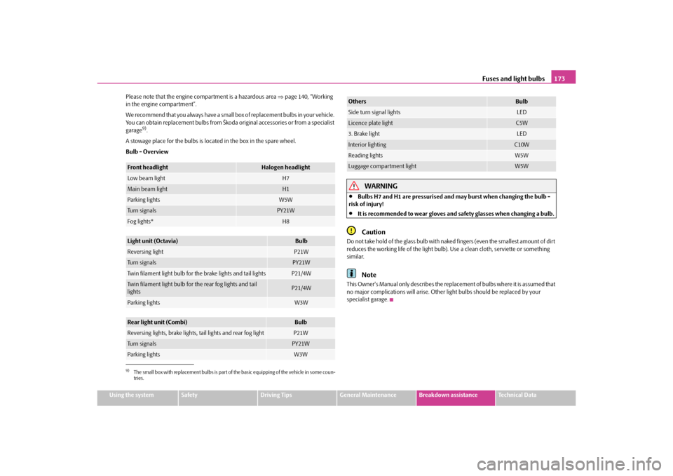
Please note that the engine compartment is a hazardous area
page 140, “Working
in the engine compartment”.
We recommend that you always have a small box of replacement bulbs in your vehicle.
You can obtain replacement bulbs from Škoda original accessories or from a specialist
garage
9).
A stowage place for the bulbs is located in the box in the spare wheel.
Bulb - Overview
WARNING
Bulbs H7 and H1 are pressurised and may burst when changing the bulb -
risk of injury!
It is recommended to wear gloves and safety glasses when changing a bulb.Caution
Do not take hold of the glass bulb with naked fingers (even the smallest amount of dirt
reduces the working life of the light bulb). Use a clean cloth, serviette or something
similar.
Note
This Owner's Manual only describes the replacement of bulbs where it is assumed that
no major complications will arise. Other li ght bulbs should be replaced by your
specialist garage.
9)The small box with replacement bulbs is part of th e basic equipping of the vehicle in some coun-
tries.Front headlight
Halogen headlight
Low beam light
H7
Main beam light
H1
Parking lights
W5W
Tu r n s i g n a l s
PY21W
Fog lights*
H8
Light unit (Octavia)
Bulb
Reversing light
P21W
Tu r n s i g n a l s
PY21W
Twin filament light bulb for the brake lights and tail lights
P21/4W
Twin filament light bulb for the rear fog lights and tail
lights
P21/4W
Parking lights
W3W
Rear light unit (Combi)
Bulb
Reversing lights, brake lights, tail lights and rear fog light
P21W
Tu r n s i g n a l s
PY21W
Parking lights
W3W
Others
Bulb
Side turn signal lights
LED
Licence plate light
C5W
3. Brake light
LED
Interior lighting
C10W
Reading lights
W5W
Luggage compartment light
W5W
s2bs.2.book Page 173 Monday, September 27, 2010 9:53 AM
Page 181 of 199

Technical Data
180
Vehicle identification number (VIN)
The vehicle identification num ber - VIN (chassis number) is stamped into the engine
compartment on the right hand shock absorb er dome. This number is also located on
a sign on the lower left hand edge below the windscreen.
Engine number
The engine number is stam ped into the engine block.
Type plate (production plate)
The type plate is located in the lowe r area of the left centre column.
Sticker on inside of fuel filler flap
The stickers are affixed to the inside of the fuel filler flap and contain the following
information:
The prescribed types of fuel,
Ty re s i z e ,
Tyre pressure.
Fuel consumption based on ECE regulations and EC guidelinesDepending on the range of the special equipment, style of driving, traffic situation,
weather influences and vehicl e condition, the consumption values which in practice
result when using the vehicle can deviate from the indicated values.
Urban traffic
The consumption measurement in urban traffic begins with starting of the cold engine.
Afterwards the normal ur ban traffic is simulated.
Non-urban traffic
For the consumption measurement in non-ur ban traffic the vehicle, as in daily
motoring, is accelerated and braked severa l times in all gears. The vehicle speed
changes within the range from 0 to 120 km/h. Combined traffic
The consumption value in the combined traffic consists of 37 % from the value for the
urban traffic and of 63 % from th
e value for the non-urban traffic.
DimensionsDimensions (mm)Engine oil specificationsThe grade of engine oil should be selected in accordance with precise
specifications.The engine of your vehicle has been factory-filled with a high-grade oil which you can
use throughout the year - except in extreme climatic regions.
You can mix various oils together with each ot her when refilling with oil. This does not,
however, apply for models with flexible service intervals (QG1).
Engine oils are, of course, undergoing continuous further development. Thus the
information stated in this Owner's Manual is only correct at the time of publication.
OCTAVIA
COMBI
Length
4572
4572
Width
1769
1769
Width including exterior mirror
2018
2018
Height
1462
1485
a)
a)The value corresponds to the status with rough road package.
1468
1490
a)
Clearance
140
164a)
140
164a)
Wheel base
2578
2578
Tr a c k g a u g e f r o n t / r e a r
1541/1514
1541/1514
s2bs.2.book Page 180 Monday, September 27, 2010 9:53 AM
Page 190 of 199

Index189
Using the system
Safety
Driving Tips
General Maintenance
Breakdown assistance
Technical Data
Index
AAbroad . . . . . . . . . . . . . . . . . . . . . . . . . . . . . . . . . . . . . . 123
ABS . . . . . . . . . . . . . . . . . . . . . . . . . . . . . . . . . . . . . . . . . 115
Warning light . . . . . . . . . . . . . . . . . . . . . . . . . . . . . 27
Accessories . . . . . . . . . . . . . . . . . . . . . . . . . . . . . . . . . . 157
Active driver-steering recommendation . . . . . . . 113
Adjusting seats . . . . . . . . . . . . . . . . . . . . . . . . . . . . 52, 86
Adjusting the steering wheel . . . . . . . . . . . . . . . . . . . 77
Air conditioning system Air outlet vents . . . . . . . . . . . . . . . . . . . . . . . . . . . . 70
Climatic . . . . . . . . . . . . . . . . . . . . . . . . . . . . . . . . . . 73
Recirculated air mode . . . . . . . . . . . . . . . . . . . . . 76
Airbag . . . . . . . . . . . . . . . . . . . . . . . . . . . . . . . . . . . . . . . 94 Deployment . . . . . . . . . . . . . . . . . . . . . . . . . . . . . . 95
Front airbag . . . . . . . . . . . . . . . . . . . . . . . . . . . . . . . 95
Head airbag . . . . . . . . . . . . . . . . . . . . . . . . . . . . . . . 99
Side airbag . . . . . . . . . . . . . . . . . . . . . . . . . . . . . . . . 97
Warning light . . . . . . . . . . . . . . . . . . . . . . . . . . . . . 24
Airbag system . . . . . . . . . . . . . . . . . . . . . . . . . . . . . . . . 94 Warning light . . . . . . . . . . . . . . . . . . . . . . . . . . . . . 24
Alarm . . . . . . . . . . . . . . . . . . . . . . . . . . . . . . . . . . . . . . . . 37
Alternator Warning light . . . . . . . . . . . . . . . . . . . . . . . . . . . . . 28
Antilock brake system . . . . . . . . . . . . . . . . . . . . . . . . 115
Antilock brake system (ABS) Warning light . . . . . . . . . . . . . . . . . . . . . . . . . . . . . 27
Anti-theft alarm system . . . . . . . . . . . . . . . . . . . . . . . 37
Ashtray . . . . . . . . . . . . . . . . . . . . . . . . . . . . . . . . . . . . . . 64
Auto Computer . . . . . . . . . . . . . . . . . . . . . . . . . . . . . . . 18 Automatic vehicle wash systems . . . . . . . . . . . . . . 129
Automatic wiper/washer system . . . . . . . . . . . . . . . 47
Avoiding damage to your vehicle . . . . . . . . . . . . . . 123
BBattery . . . . . . . . . . . . . . . . . . . . . . . . . . . . . . . . . . 28, 146
change . . . . . . . . . . . . . . . . . . . . . . . . . . . . . . . . . . 149
Charge . . . . . . . . . . . . . . . . . . . . . . . . . . . . . . . . . . . 149
Inspecting the electrolyte level . . . . . . . . . . . . . 148
Operation in winter . . . . . . . . . . . . . . . . . . . . . . . 148
Before setting off . . . . . . . . . . . . . . . . . . . . . . . . . . . . . . 85
Belt Warning light . . . . . . . . . . . . . . . . . . . . . . . . . . . . . . 28
Belt tensioners . . . . . . . . . . . . . . . . . . . . . . . . . . . . . . . . 92
Belts . . . . . . . . . . . . . . . . . . . . . . . . . . . . . . . . . . . . . . . . . 89
Bonnet . . . . . . . . . . . . . . . . . . . . . . . . . . . . . . . . . . 13, 139 Warning light . . . . . . . . . . . . . . . . . . . . . . . . . . . . . . 27
Boot lid . . . . . . . . . . . . . . . . . . . . . . . . . . . . . . . . . . . . . . 35 Lighting . . . . . . . . . . . . . . . . . . . . . . . . . . . . . . . . . . . 46
Warning light . . . . . . . . . . . . . . . . . . . . . . . . . . . . . . 28
Brake Handbrake . . . . . . . . . . . . . . . . . . . . . . . . . . . . . . . . 80
Warning light . . . . . . . . . . . . . . . . . . . . . . . . . . . . . . 28
Brake Assist . . . . . . . . . . . . . . . . . . . . . . . . . . . . . . . . . . 115
Brake booster . . . . . . . . . . . . . . . . . . . . . . . . . . . . . . . . 114
Brake fluid . . . . . . . . . . . . . . . . . . . . . . . . . . . . . . . . . . . 145
Brake pads Warning light . . . . . . . . . . . . . . . . . . . . . . . . . . . . . . 28
Brakes . . . . . . . . . . . . . . . . . . . . . . . . . . . . . . . . . . . . . . 113 Bulbs
Warning light . . . . . . . . . . . . . . . . . . . . . . . . . . . . . . 24
Button for the central locking system . . . . . . . . . . . 33
Buttons on the driver's door Power windows . . . . . . . . . . . . . . . . . . . . . . . . . . . 39
CCatalytic converter . . . . . . . . . . . . . . . . . . . . . . . . . . 119
Central locking system . . . . . . . . . . . . . . . . . . . . . . . . . 31lock . . . . . . . . . . . . . . . . . . . . . . . . . . . . . . . . . . . . . . . 33
unlock . . . . . . . . . . . . . . . . . . . . . . . . . . . . . . . . . . . . 33
Changing a wheel . . . . . . . . . . . . . . . . . . . . . . . . . . . 161
Changing bulbs . . . . . . . . . . . . . . . . . . . . . . . . . . . . . 172
Changing the engine oil . . . . . . . . . . . . . . . . . . . . . . 142
Changing wheels around . . . . . . . . . . . . . . . . . . . . 153
Charging the battery . . . . . . . . . . . . . . . . . . . . . . . . . 149 Warning light . . . . . . . . . . . . . . . . . . . . . . . . . . . . . . 28
Check engine oil level . . . . . . . . . . . . . . . . . . . . . . . 141
Child safety . . . . . . . . . . . . . . . . . . . . . . . . . . . . . . . . . 103 Side airbag . . . . . . . . . . . . . . . . . . . . . . . . . . . . . . 105
Child safety lock . . . . . . . . . . . . . . . . . . . . . . . . . . . . . . . 31
Child safety seat on the front passenger seat . . . . . . . . . . . . . . . 104
Safety information . . . . . . . . . . . . . . . . . . . . . . . 103
Child seat . . . . . . . . . . . . . . . . . . . . . . . . . . . . . . . . . . . 105 Classification into groups . . . . . . . . . . . . . . . . . 105
ISOFIX system . . . . . . . . . . . . . . . . . . . . . . . . . . . 108
Use of child safety seats . . . . . . . . . . . . . . . . . . 106
Children and safety . . . . . . . . . . . . . . . . . . . . . . . . . . 103
s2bs.2.book Page 189 Monday, September 27, 2010 9:53 AM