dash SKODA OCTAVIA TOUR 2010 2.G / (1Z) Owner's Manual
[x] Cancel search | Manufacturer: SKODA, Model Year: 2010, Model line: OCTAVIA TOUR, Model: SKODA OCTAVIA TOUR 2010 2.G / (1Z)Pages: 199, PDF Size: 12.09 MB
Page 4 of 199
Contents3
Using the system
Safety
Driving Tips
General Maintenance
Breakdown assistance
Technical Data
ContentsLayout of this Owner's Manual
(explanations)
. . . . . . . . . . . . . . . . . . . . . . . . . .
Using the system
. . . . . . . . . . . . . . . . . . . . . .
Cockpit
. . . . . . . . . . . . . . . . . . . . . . . . . . . . . . . . . . . . . . . .
Overview . . . . . . . . . . . . . . . . . . . . . . . . . . . . . . . . . . . .
The brief instruction
. . . . . . . . . . . . . . . . . . . . . . . . . .
Basic functions and important information . . . . .
Instruments and Indic ator/Warning Lights
. . .
Overview of the instrument cluster . . . . . . . . . . . . .
Engine revolutions counter . . . . . . . . . . . . . . . . . . . .
Speedometer . . . . . . . . . . . . . . . . . . . . . . . . . . . . . . . .
Engine coolant temperature Display . . . . . . . . . . .
Fuel gauge . . . . . . . . . . . . . . . . . . . . . . . . . . . . . . . . . . .
Counter for distance driven . . . . . . . . . . . . . . . . . . .
Service Interval Display . . . . . . . . . . . . . . . . . . . . . . .
Digital clock . . . . . . . . . . . . . . . . . . . . . . . . . . . . . . . . . .
Recommended gear* . . . . . . . . . . . . . . . . . . . . . . . . .
Multi-functional indicator (onboard computer)*
Warning lights . . . . . . . . . . . . . . . . . . . . . . . . . . . . . . . .
Unlocking and locking
. . . . . . . . . . . . . . . . . . . . . . . .
Key . . . . . . . . . . . . . . . . . . . . . . . . . . . . . . . . . . . . . . . . . .
Changing the battery in the remote control key .
Electronic immobiliser . . . . . . . . . . . . . . . . . . . . . . . .
Child safety lock . . . . . . . . . . . . . . . . . . . . . . . . . . . . . .
Central locking system . . . . . . . . . . . . . . . . . . . . . . . .
Remote control* . . . . . . . . . . . . . . . . . . . . . . . . . . . . . .
Synchronisation of the remote control . . . . . . . . . .
Anti-theft alarm system* . . . . . . . . . . . . . . . . . . . . . .
Power windows* . . . . . . . . . . . . . . . . . . . . . . . . . . . . .
Lights and Visibility
. . . . . . . . . . . . . . . . . . . . . . . . . . .
Lights . . . . . . . . . . . . . . . . . . . . . . . . . . . . . . . . . . . . . . . .
Interior lighting . . . . . . . . . . . . . . . . . . . . . . . . . . . . . . . Visibility . . . . . . . . . . . . . . . . . . . . . . . . . . . . . . . . . . . . . .
Windshield wiper and wash system . . . . . . . . . . . . .
Rear-view mirror . . . . . . . . . . . . . . . . . . . . . . . . . . . . . .
Seats and Stowage
. . . . . . . . . . . . . . . . . . . . . . . . . . . . .
Front seats . . . . . . . . . . . . . . . . . . . . . . . . . . . . . . . . . . . .
Head restraints . . . . . . . . . . . . . . . . . . . . . . . . . . . . . . . .
Middle rear head restraint* . . . . . . . . . . . . . . . . . . . .
Rear seats . . . . . . . . . . . . . . . . . . . . . . . . . . . . . . . . . . . .
Pedals . . . . . . . . . . . . . . . . . . . . . . . . . . . . . . . . . . . . . . . .
luggage compartment . . . . . . . . . . . . . . . . . . . . . . . . .
Net partition* (Combi) . . . . . . . . . . . . . . . . . . . . . . . .
The roof rack* . . . . . . . . . . . . . . . . . . . . . . . . . . . . . . . .
Cup holder . . . . . . . . . . . . . . . . . . . . . . . . . . . . . . . . . . .
Note holder . . . . . . . . . . . . . . . . . . . . . . . . . . . . . . . . . .
Ashtray* . . . . . . . . . . . . . . . . . . . . . . . . . . . . . . . . . . . . . .
Cigarette lighter*, power sockets . . . . . . . . . . . . . . .
Storage compartments . . . . . . . . . . . . . . . . . . . . . . . .
Overview . . . . . . . . . . . . . . . . . . . . . . . . . . . . . . . . . . . . .
Storage compartment on the front passenger side
Storage compartment on the driver's side . . . . . . .
Storage compartment on the dash panel . . . . . . . .
Storage compartment in front centre console* . .
Storage compartment in the front doors . . . . . . . .
Front seat armrest with storage compartment* . .
Rear seat armrest with storage compartment* . . .
Storage compartment in rear centre console* . . .
Seat backrest with opening for skis* . . . . . . . . . . . .
Clothes hooks* . . . . . . . . . . . . . . . . . . . . . . . . . . . . . . .
Heating and air conditioning system
. . . . . . . . . .
Air outlet vents . . . . . . . . . . . . . . . . . . . . . . . . . . . . . . . .
Heating . . . . . . . . . . . . . . . . . . . . . . . . . . . . . . . . . . . . . .
Climatic* . . . . . . . . . . . . . . . . . . . . . . . . . . . . . . . . . . . . .
Starting-off and Driving
. . . . . . . . . . . . . . . . . . . . . . .
Setting steering wheel position . . . . . . . . . . . . . . . . .
Ignition lock . . . . . . . . . . . . . . . . . . . . . . . . . . . . . . . . . . Starting the engine . . . . . . . . . . . . . . . . . . . . . . . . . . . .
Switching off the engine . . . . . . . . . . . . . . . . . . . . . . .
Shifting . . . . . . . . . . . . . . . . . . . . . . . . . . . . . . . . . . . . . .
Handbrake . . . . . . . . . . . . . . . . . . . . . . . . . . . . . . . . . . .
Rear parking aid* . . . . . . . . . . . . . . . . . . . . . . . . . . . . .
Cruise control system (CCS)* . . . . . . . . . . . . . . . . . .
Communication
. . . . . . . . . . . . . . . . . . . . . . . . . . . . . . .
Mobile phones and two-way radio systems . . . . .
Safety
. . . . . . . . . . . . . . . . . . . . . . . . . . . . . . . . . . . . . . .
Passive Safety
. . . . . . . . . . . . . . . . . . . . . . . . . . . . . . . . .
Basic information . . . . . . . . . . . . . . . . . . . . . . . . . . . . .
Correct seated position . . . . . . . . . . . . . . . . . . . . . . .
Seat belts
. . . . . . . . . . . . . . . . . . . . . . . . . . . . . . . . . . . . . .
Why seat belts? . . . . . . . . . . . . . . . . . . . . . . . . . . . . . . .
The physical principle of a frontal collision . . . . . .
Important safety information regarding the use of seat
belts . . . . . . . . . . . . . . . . . . . . . . . . . . . . . . . . . . . . . . . . .
How are seat belts correctly fastened? . . . . . . . . . .
Airbag system
. . . . . . . . . . . . . . . . . . . . . . . . . . . . . . . . .
Description of the airbag system . . . . . . . . . . . . . . .
Front airbags . . . . . . . . . . . . . . . . . . . . . . . . . . . . . . . . .
side airbags* . . . . . . . . . . . . . . . . . . . . . . . . . . . . . . . . .
Head airbags* . . . . . . . . . . . . . . . . . . . . . . . . . . . . . . . .
Deactivating an airbag . . . . . . . . . . . . . . . . . . . . . . . .
Transporting children safely
. . . . . . . . . . . . . . . . . .
What you should know about transporting children!
Child seat . . . . . . . . . . . . . . . . . . . . . . . . . . . . . . . . . . . .
Attaching a child seat using the “ISOFIX” system .
Attaching child seat using the “Top Tether”* system
6799101015151516161616171818182230303031313136373739424245
4647505252535454565761626364646465656666666767676868696970707173777777
78798080818284848585858689898990919494959799101103103105108109
s2bs.2.book Page 3 Monday, September 27, 2010 9:53 AM
Page 10 of 199
Cockpit9
Using the system
Safety
Driving Tips
General Maintenance
Breakdown assistance
Technical Data
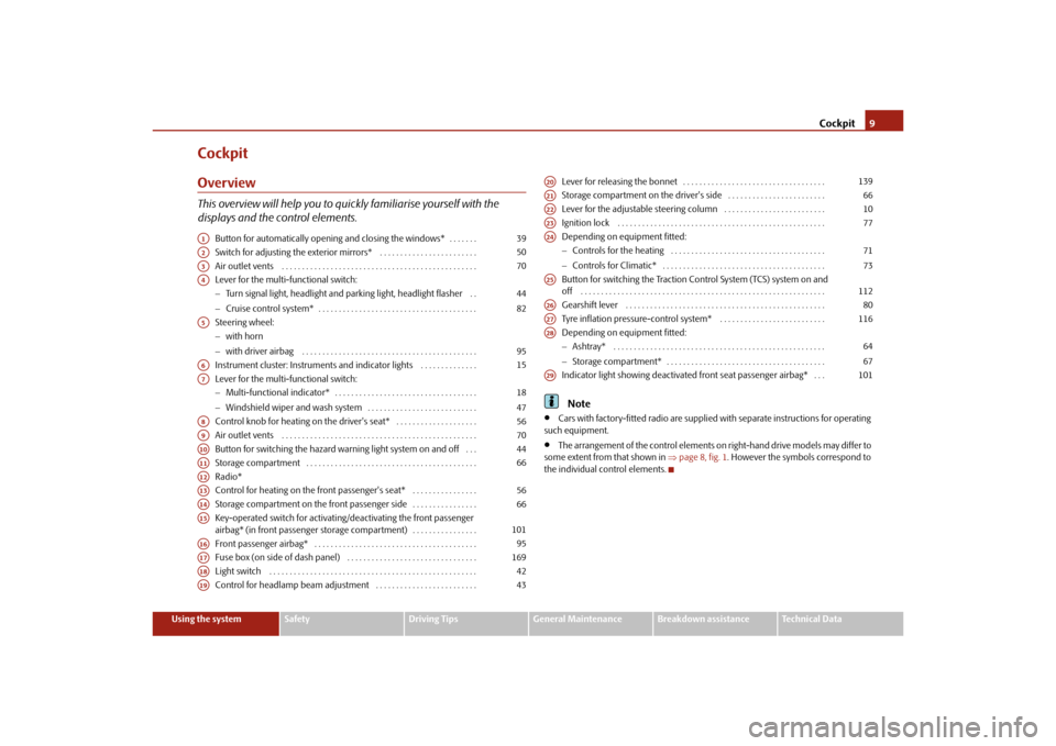
CockpitOverviewThis overview will help you to quic kly familiarise yourself with the
displays and the control elements.
Button for automatically opening and closing the windows* . . . . . . .
Switch for adjusting the exterior mirrors* . . . . . . . . . . . . . . . . . . . . . . . .
Air outlet vents . . . . . . . . . . . . . . . . . . . . . . . . . . . . . . . . . . . . . . . . . . . . . . . .
Lever for the multi-functional switch:
Turn signal light, headlight and parking light, headlight flasher . .
Cruise control system* . . . . . . . . . . . . . . . . . . . . . . . . . . . . . . . . . . . . . . .
Steering wheel:
with horn
with driver airbag . . . . . . . . . . . . . . . . . . . . . . . . . . . . . . . . . . . . . . . . . . .
Instrument cluster: Instruments and indicator lights . . . . . . . . . . . . . .
Lever for the multi-functional switch:
Multi-functional indicator* . . . . . . . . . . . . . . . . . . . . . . . . . . . . . . . . . . .
Windshield wiper and wash system . . . . . . . . . . . . . . . . . . . . . . . . . . .
Control knob for heating on the driver's seat* . . . . . . . . . . . . . . . . . . . .
Air outlet vents . . . . . . . . . . . . . . . . . . . . . . . . . . . . . . . . . . . . . . . . . . . . . . . .
Button for switching the hazard warning light system on and off . . .
Storage compartment . . . . . . . . . . . . . . . . . . . . . . . . . . . . . . . . . . . . . . . . . .
Radio*
Control for heating on the front passenger's seat* . . . . . . . . . . . . . . . .
Storage compartment on the front passenger side . . . . . . . . . . . . . . . .
Key-operated switch for activating/deactivating the front passenger
airbag* (in front passenger storage compartment) . . . . . . . . . . . . . . . .
Front passenger airbag* . . . . . . . . . . . . . . . . . . . . . . . . . . . . . . . . . . . . . . . .
Fuse box (on side of dash panel) . . . . . . . . . . . . . . . . . . . . . . . . . . . . . . . .
Light switch . . . . . . . . . . . . . . . . . . . . . . . . . . . . . . . . . . . . . . . . . . . . . . . . . . .
Control for headlamp beam adjustment . . . . . . . . . . . . . . . . . . . . . . . . . Lever for releasing the bonnet . . . . . . . . . . . . . . . . . . . . . . . . . . . . . . . . . . .
Storage compartment on the driver's side . . . . . . . . . . . . . . . . . . . . . . . .
Lever for the adjustable steering column . . . . . . . . . . . . . . . . . . . . . . . . .
Ignition lock . . . . . . . . . . . . . . . . . . . . . . . . . . . . . . . . . . . . . . . . . . . . . . . . . . .
Depending on equipment fitted:
Controls for the heating . . . . . . . . . . . . . . . . . . . . . . . . . . . . . . . . . . . . . .
Controls for Climatic* . . . . . . . . . . . . . . . . . . . . . . . . . . . . . . . . . . . . . . . .
Button for switching the Traction Control System (TCS) system on and
off . . . . . . . . . . . . . . . . . . . . . . . . . . . . . . . . . . . . . . . . . . . . . . . . . . . . . . . . . . . .
Gearshift lever . . . . . . . . . . . . . . . . . . . . . . . . . . . . . . . . . . . . . . . . . . . . . . . . .
Tyre inflation pressure-control system* . . . . . . . . . . . . . . . . . . . . . . . . . .
Depending on equipment fitted:
Ashtray* . . . . . . . . . . . . . . . . . . . . . . . . . . . . . . . . . . . . . . . . . . . . . . . . . . . .
Storage compartment* . . . . . . . . . . . . . . . . . . . . . . . . . . . . . . . . . . . . . . .
Indicator light showing deactivated front seat passenger airbag* . . .
Note
Cars with factory-fitted radio are supplied with separate instructions for operating
such equipment.
The arrangement of the control elements on right-hand drive models may differ to
some extent from that shown in page 8, fig. 1 . However the symbols correspond to
the individual control elements.
A1
39
A2
50
A3
70
A4
4482
A5
95
A6
15
A7
1847
A8
56
A9
70
A10
44
A11
66
A12A13
56
A14
66
A15
101
A16
95
A17
169
A18
42
A19
43
A20
139
A21
66
A22
10
A23
77
A24
7173
A25
112
A26
80
A27
116
A28
6467
A29
101
s2bs.2.book Page 9 Monday, September 27, 2010 9:53 AM
Page 13 of 199
The brief instruction
12
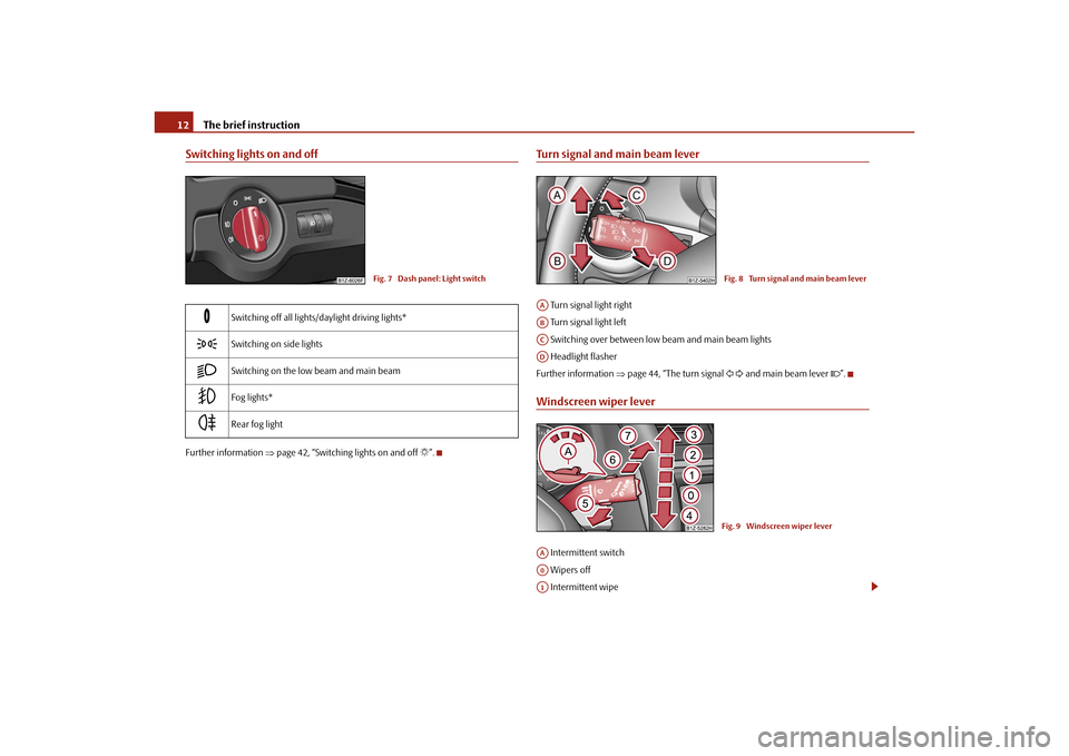
Switching lights on and offFurther information page 42, “Switching lights on and off ”.
Turn signal and main beam lever Turn signal light right
Turn signal light left
Switching over between low beam and main beam lights
Headlight flasher
Further information page 44, “The turn signal and main beam lever ”.Windscreen wiper lever Intermittent switch
Wipers off
Intermittent wipe
Switching off all lights/daylight driving lights*
Switching on side lights
Switching on the low beam and main beam
Fog lights*
Rear fog light
Fig. 7 Dash panel: Light switch
Fig. 8 Turn signal and main beam lever
AAABACAD
Fig. 9 Windscreen wiper lever
AAA0A1
s2bs.2.book Page 12 Monday, September 27, 2010 9:53 AM
Page 14 of 199
The brief instruction13
Using the system
Safety
Driving Tips
General Maintenance
Breakdown assistance
Technical Data
Slow wipe
Fast wipe
one time wipe
Automatic wipe/wash
Rear window wiper* Intermittent wipe - every 6 seconds
The automatic wiper/washer system
Further information page 47, “Windshield wiper”.
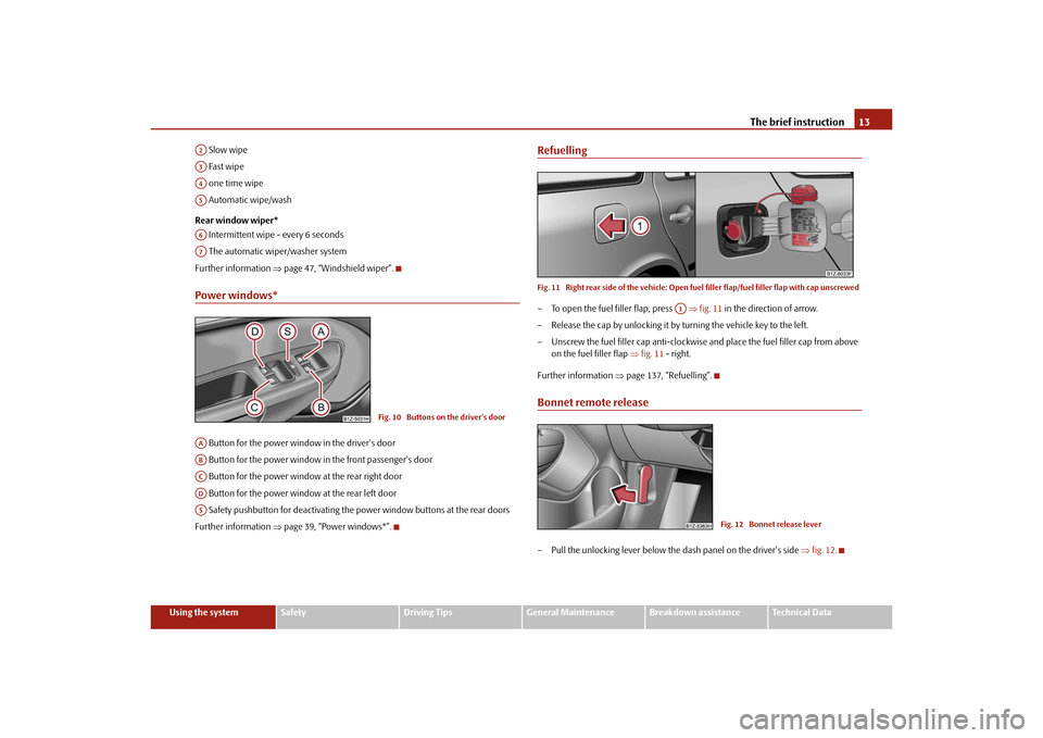
Power windows* Button for the power window in the driver's door
Button for the power window in the front passenger's door
Button for the power window at the rear right door
Button for the power window at the rear left door
Safety pushbutton for deactivating the power window buttons at the rear doors
Further information page 39, “Power windows*”.
RefuellingFig. 11 Right rear side of the vehicle: Open fu el filler flap/fuel filler flap with cap unscrewed– To open the fuel filler flap, press fig. 11 in the direction of arrow.
– Release the cap by unlocking it by turning the vehicle key to the left.
– Unscrew the fuel filler ca p anti-clockwise and place the fuel filler cap from above
on the fuel filler flap fig. 11 - right.
Further information page 137, “Refuelling”.Bonnet remote release– Pull the unlocking lever below the dash panel on the driver's side fig. 12 .
A2A3A4A5A6A7
Fig. 10 Buttons on the driver's door
AAABACADAS
A1
Fig. 12 Bonnet release lever
s2bs.2.book Page 13 Monday, September 27, 2010 9:53 AM
Page 18 of 199
Instruments and Indicator/Warning Lights17
Using the system
Safety
Driving Tips
General Maintenance
Breakdown assistance
Technical Data
Odometer
The odometer indicates the total distance in
kilometres or miles which the vehicle has
been driven.
Fa u l t d i s p l a y
If there is a fault in the instrument cluster Error will appear in the display. Contact a
specialist garage.
WARNING
Never seek to adjust the trip counter for distance driven while driving for safety
reasons!
Note
If the display of the second speed is acti vated in mph or km/h, this speed is shown
instead of the odometer on the display.Service Interval DisplayService Interval Display
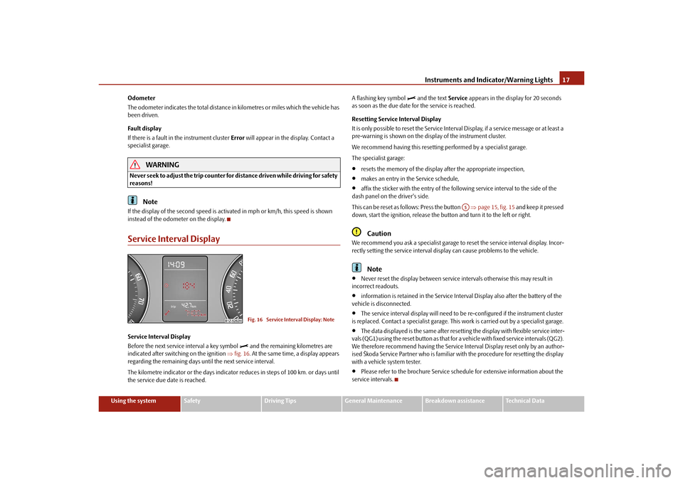
Before the next service interval a key symbol
and the remaining kilometres are
indicated after switching on the ignition fig. 16. At the same time, a display appears
regarding the remaining days until the next service interval.
The kilometre indicator or the days indicator reduces in steps of 100 km. or days until
the service due date is reached. A flashing key symbol
and the text
Service appears in the display for 20 seconds
as soon as the due date for the service is reached.
Resetting Service Interval Display
It is only possible to reset the Service Interval Display, if a service message or at least a
pre-warning is shown on the disp lay of the instrument cluster.
We recommend having this resetting performed by a specialist garage.
The specialist garage:
resets the memory of the display after the appropriate inspection,
makes an entry in the Service schedule,
affix the sticker with the entry of the following service interval to the side of the
dash panel on the driver's side.
This can be reset as follows: Press the button page 15, fig. 15 and keep it pressed
down, start the ignition, release the butt on and turn it to the left or right.Caution
We recommend you ask a specialist garage to reset the service interval display. Incor-
rectly setting the service interval display can cause problems to the vehicle.
Note
Never reset the display between service intervals otherwise this may result in
incorrect readouts.
information is retained in the Service Inte rval Display also after the battery of the
vehicle is disconnected.
The service interval display will need to be re-configured if the instrument cluster
is replaced. Contact a specialist garage. This work is carried out by a specialist garage.
The data displayed is the same after resetting the display with flexible service inter-
vals (QG1) using the reset button as that for a vehicle with fixed service intervals (QG2).
We therefore recommend having the Service In terval Display reset only by an author-
ised Škoda Service Partner who is familiar with the procedure for resetting the display
with a vehicle system tester.
Please refer to the brochure Service schedule for extensive information about the
service intervals.
Fig. 16 Service Interval Display: Note
A5
s2bs.2.book Page 17 Monday, September 27, 2010 9:53 AM
Page 22 of 199
Instruments and Indicator/Warning Lights21
Using the system
Safety
Driving Tips
General Maintenance
Breakdown assistance
Technical Data
The maximum distance indicated in both switch positions is 1,999 km. The indicator is
set back to null if this
period is exceeded.
Average speedThe average speed since the memory was last erased is shown in the display in
km/hour page 18. If you wish to determine the average speed over a certain period
of time, you must set the memory at the start of the new measurement to zero using
the button on the windshield wiper lever page 19, fig. 19 .
Dashes appear in the display for the first 100 m you drive after erasing the memory.
The indicated value will be updated every 5 seconds while you are driving.Current speed*The current speed is displayed on the display. It is identical to the display on the
tachometer (speedometer) page 15, fig. 15 .
Note
If the display of the second speed is activa ted in mph, the current speed* is not indi-
cated in km/h on the display.Warning against excessive speeds*This function enables you to set a speed li mit and will notify you if you exceed this
speed limit.Configuring the speed limit while the vehicle is stationary– With switch page 19, fig. 19 , choose the menu point Warning against
excessive speeds .
– Press the switch to activate configurat ion of the speed limit (the value flashes).
– Use switch to set the required speed limit, e.g. 50 km/h.
– Confirm the speed limit that was set with button , or wait 5 seconds until the setting is saved automatically (the value stops flashing). In this way you can set the limit in 5 km/h steps.
Configuring the speed limit while the vehicle is moving– With switch , choose the menu point
Warning against excessive speeds.
– Drive e.°g at a speed of 50 km/h.
– Press the switch to accept the curr ent speed as the speed limit (the value
flashes).
If you wish to change the speed limit that was set, it is changed in 5 km/h intervals (e.g.
the accepted speed of 47 km/h increases to 50 km/h or decreases to 45 km/h).
– Confirm the speed limit that was set by pressing button again, or wait 5 seconds until the setting is saved automati cally (the value stops flashing).Changing or erasing the speed limit– With switch , choose the menu point Warning against excessive speeds.
– When you press the switch ag ain, the speed limit is erased.
– Pressing the switch a further time activates the change mode for the speed limit.
If you exceed the configured speed, an ac oustic signal will sound as a warning. A
Warning against excessive speeds appears together with the set limit on the display.
The set speed limit remains stored even after switching off the ignition.
WARNING
Pay attention primarily to the traffic situation! As the driver you are fully
responsible for road safety.
AB
A2
AA
AB
AA
AB
AA
AB
AB
AA
AB
AB
s2bs.2.book Page 21 Monday, September 27, 2010 9:53 AM
Page 25 of 199
Instruments and Indicator/Warning Lights
24
Further information about the main beam page 44.Low beam
The warning light
comes on when low beam is selected page 42.
Rear fog light
The warning light
comes on when the rear fog lights are operating page 43.
Cruise control system*
The warning light
lights up, when operating the speed regulating system.
Bulb failure
The warning light
comes on if a bulb is faulty:
up to 2 seconds after the ignition is switched on,
when switching on the defective light bulb.
The rear side lights and the licence plate li ghting require several light bulbs. The indi-
cator light
only lights up if all light bulbs of the licence plate lighting or the parking
light (in one rear light unit) are defective. Check regularly the function of the light
bulbs.
Airbag system
Monitoring the airbag system
The warning light
comes on for a few seconds when the ignition is switched on.
There is a fault in the system if the warning light does not go out or flashes while driving
. This also applies if the warning light does not come on when the ignition is
switched on.
The functionality of the airbag system is also monitored electronically when one airbag
has been switched off. Front, side and head airbags or belt tensioner which have been switched off
using the vehicle
system tester:
The warning light
lights up for 4 seconds after switching on the ignition and then
flashes again for 12 seconds in intervals of 2 seconds.
Front passenger airbags sw itched off using the switch for front passenger
airbags* in storage compartmen t on the front passenger side:
the warning light
comes on for 4 seconds after the ignition has been switched
on,
switching off the airbag is indicated in the middle of the dash panel by the lighting
up of the indicator light
(airbag switched off) page 101.
WARNING
Have the airbag system checked immediat ely by a specialist garage if a fault
exists. Otherwise, there is a risk of the airbag not being activated in the event of
an accident.Control system for exhaust
The warning light
comes on after the ignition has been switched on.
If the warning light does not go out after starti ng the engine or it lights up when driving,
a fault exists in an exhaust relevant co mponent. The engine management system
selects an emergency programme which enables you to drive to the nearest specialist
garage by adopting a ge ntle style of driving.
Electromechanical power steering
The warning light
comes on for a few seconds when the ignition is switched on.
If the warning light after switching on the ignition or when driving lights up continu-
ously, a fault exists in the electromechanical power steering.
If the yellow warning light lights up
, this indicates a partial failure of the power
steering and the steering forces can be greater.
If the red warning light lights up
, this indicates a complete failure of the power
steering and the steering assist has failed (significantly higher steering forces).
s2bs.2.book Page 24 Monday, September 27, 2010 9:53 AM
Page 43 of 199
Lights and Visibility
42
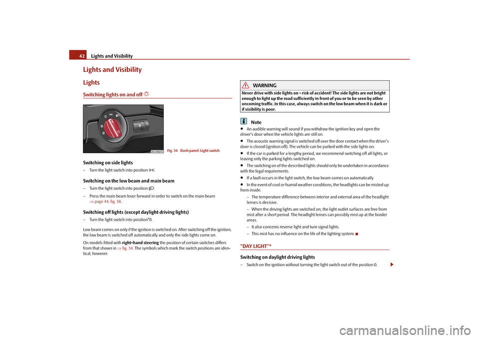
Lights and VisibilityLightsSwitching lights on and off
Switching on side lights– Turn the light switch into position
.
Switching on the low beam and main beam– Turn the light switch into position
.
– Press the main beam lever forward in order to switch on the main beam page 44, fig. 38 .
Switching off lights (except daylight driving lights)– Turn the light switch into position°0.
Low beam comes on only if the ignition is switched on. After switching off the ignition,
the low beam is switched off automatica lly and only the side lights come on.
On models fitted with right-hand steering the position of certain switches differs
from that shown in fig. 34 . The symbols which mark the switch positions are iden-
tical, however.
WARNING
Never drive with side lights on - risk of accident! The side lights are not bright
enough to light up the road sufficiently in front of you or to be seen by other
oncoming traffic. In this case, always switch on the low beam when it is dark or
if visibility is poor.
Note
An audible warning will sound if you wi thdraw the ignition key and open the
driver's door when the vehicle lights are still on.
The acoustic warning signal is switched off over the door contact when the driver's
door is closed (ignition off). The vehicle can be parked with the side lights on.
If the car is parked for a lengthy period, we recommend switching off all lights, or
leaving only the parking lights switched on.
The switching on of the described lights should only be undertaken in accordance
with the legal requirements.
If a fault occurs in the light switch , the low beam comes on automatically
In the event of cool or humid weather conditions, the headlights can be misted up
from inside.
The temperature difference between interior and external area of the headlight
lenses is decisive.
When the driving lights are switched on, the light outlet surfaces are free from
mist after a short period. The headlight lens es can possibly mist up at the border
areas.
It also concerns reverse light and turn signal lights.
This mist has no influence on th e life of the lighting system.
“DAY LIGHT”* Switching on daylight driving lights– Switch on the ignition without turning the light switch out of the position 0.
Fig. 34 Dash panel: Light switch
s2bs.2.book Page 42 Monday, September 27, 2010 9:53 AM
Page 44 of 199
Lights and Visibility43
Using the system
Safety
Driving Tips
General Maintenance
Breakdown assistance
Technical Data
Deactivating the function daylight driving lights– Pull the turn signal light lever towards the steering wheel up to 3 seconds after
switching on the ignition and at the same time, slide it to the bottom and hold it in
this position for at least 3 seconds.Activating the function daylight driving lights– Pull the turn signal light lever towards the steering wheel up to 3 seconds after
switching on the ignition and at the same time, slide it to the top and hold it in this
position for at least 3 seconds.
The daytime driving light is a combination of low-beam and parking light (front and
rear), including licence plate light.
When the daylight driving lights are switched on, the lighting of the instrument cluster
is switched on as well.Fog lights*
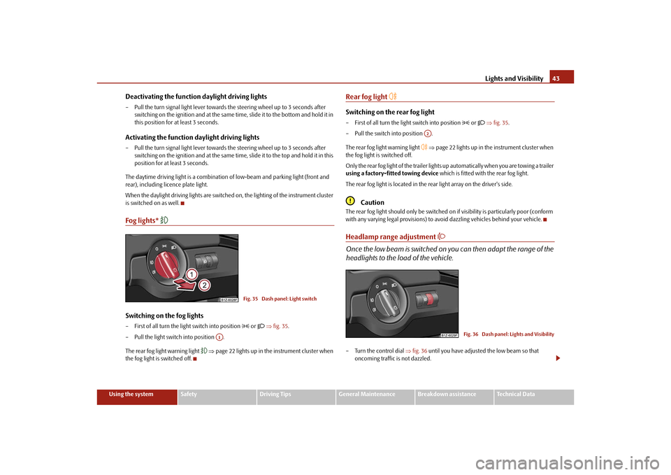
Switching on the fog lights– First of all turn the light switch into position
or fig. 35 .
– Pull the light switch into position .
The rear fog light warning light
page 22 lights up in the instrument cluster when
the fog light is switched off.
Rear fog light
Switching on the rear fog light– First of all turn the light switch into position
or fig. 35 .
– Pull the switch into position .
The rear fog light warning light
page 22 lights up in the instrument cluster when
the fog light is switched off.
Only the rear fog light of the trailer lights up automatically when you are towing a trailer
using a factory-fitted towing device which is fitted with the rear fog light.
The rear fog light is located in the rear light array on the driver's side.
Caution
The rear fog light should only be switched on if visibility is particularly poor (conform
with any varying legal provisions) to avoi d dazzling vehicles behind your vehicle.Headlamp range adjustment
Once the low beam is switched on you can then adapt the range of the
headlights to the load of the vehicle.– Turn the control dial fig. 36 until you have adjusted the low beam so that
oncoming traffic is not dazzled.
Fig. 35 Dash panel: Light switch
A1
A2
Fig. 36 Dash panel: Lights and Visibility
s2bs.2.book Page 43 Monday, September 27, 2010 9:53 AM
Page 45 of 199
Lights and Visibility
44
Settings
The positions correspond approximately to the following vehicle loads:
Front seats occupied, luggage compartment empty.
All seats occupied, luggage compartment empty.
All seats occupied, luggage compartment laden.
Driver seat occupied, lu ggage compartment laden.
Caution
Set the headlight beam adjustment in su ch a way as to avoid dazzling oncoming
traffic.Switch for hazard warning lights
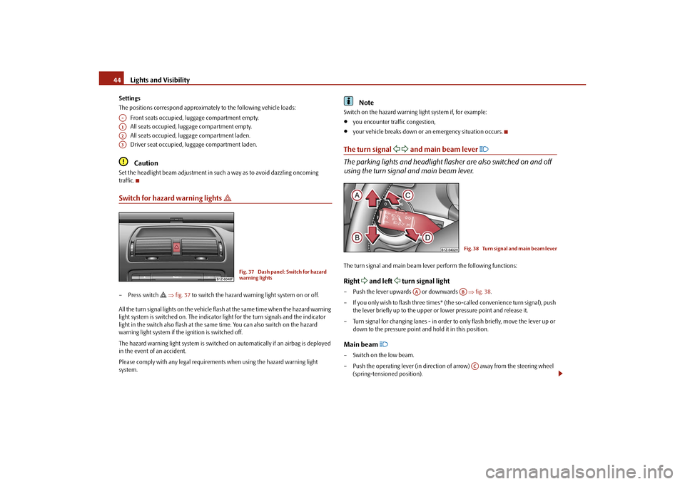
– Press switch
fig. 37 to switch the hazard warning light system on or off.
All the turn signal lights on the vehicle flas h at the same time when the hazard warning
light system is switched on. The indicator light for the turn signals and the indicator
light in the switch also flash at the same time. You can also switch on the hazard
warning light system if the ignition is switched off.
The hazard warning light system is switched on automatically if an airbag is deployed
in the event of an accident.
Please comply with any legal requirements when using the hazard warning light
system.
Note
Switch on the hazard warning light system if, for example:
you encounter traffic congestion,
your vehicle breaks down or an emergency situation occurs.
The turn signal
and main beam lever
The parking lights and headlight flasher are also switched on and off
using the turn signal and main beam lever.The turn signal and main beam le ver perform the following functions:Right
and left
turn signal light
– Push the lever upwards or downwards fig. 38 .
– If you only wish to flash three times* (the so-called convenience turn signal), push
the lever briefly up to the upper or lower pressure point and release it.
– Turn signal for changing lanes - in order to only flash briefly, move the lever up or down to the pressure point and hold it in this position.Main beam
– Switch on the low beam.
– Push the operating lever (in direction of arrow) away from the steering wheel
(spring-tensioned position).
A-A1A2A3
Fig. 37 Dash panel: Switch for hazard
warning lights
Fig. 38 Turn signal and main beam lever
AA
AB
AC
s2bs.2.book Page 44 Monday, September 27, 2010 9:53 AM