mirror SKODA OCTAVIA TOUR 2010 2.G / (1Z) Owner's Manual
[x] Cancel search | Manufacturer: SKODA, Model Year: 2010, Model line: OCTAVIA TOUR, Model: SKODA OCTAVIA TOUR 2010 2.G / (1Z)Pages: 199, PDF Size: 12.09 MB
Page 4 of 199
Contents3
Using the system
Safety
Driving Tips
General Maintenance
Breakdown assistance
Technical Data
ContentsLayout of this Owner's Manual
(explanations)
. . . . . . . . . . . . . . . . . . . . . . . . . .
Using the system
. . . . . . . . . . . . . . . . . . . . . .
Cockpit
. . . . . . . . . . . . . . . . . . . . . . . . . . . . . . . . . . . . . . . .
Overview . . . . . . . . . . . . . . . . . . . . . . . . . . . . . . . . . . . .
The brief instruction
. . . . . . . . . . . . . . . . . . . . . . . . . .
Basic functions and important information . . . . .
Instruments and Indic ator/Warning Lights
. . .
Overview of the instrument cluster . . . . . . . . . . . . .
Engine revolutions counter . . . . . . . . . . . . . . . . . . . .
Speedometer . . . . . . . . . . . . . . . . . . . . . . . . . . . . . . . .
Engine coolant temperature Display . . . . . . . . . . .
Fuel gauge . . . . . . . . . . . . . . . . . . . . . . . . . . . . . . . . . . .
Counter for distance driven . . . . . . . . . . . . . . . . . . .
Service Interval Display . . . . . . . . . . . . . . . . . . . . . . .
Digital clock . . . . . . . . . . . . . . . . . . . . . . . . . . . . . . . . . .
Recommended gear* . . . . . . . . . . . . . . . . . . . . . . . . .
Multi-functional indicator (onboard computer)*
Warning lights . . . . . . . . . . . . . . . . . . . . . . . . . . . . . . . .
Unlocking and locking
. . . . . . . . . . . . . . . . . . . . . . . .
Key . . . . . . . . . . . . . . . . . . . . . . . . . . . . . . . . . . . . . . . . . .
Changing the battery in the remote control key .
Electronic immobiliser . . . . . . . . . . . . . . . . . . . . . . . .
Child safety lock . . . . . . . . . . . . . . . . . . . . . . . . . . . . . .
Central locking system . . . . . . . . . . . . . . . . . . . . . . . .
Remote control* . . . . . . . . . . . . . . . . . . . . . . . . . . . . . .
Synchronisation of the remote control . . . . . . . . . .
Anti-theft alarm system* . . . . . . . . . . . . . . . . . . . . . .
Power windows* . . . . . . . . . . . . . . . . . . . . . . . . . . . . .
Lights and Visibility
. . . . . . . . . . . . . . . . . . . . . . . . . . .
Lights . . . . . . . . . . . . . . . . . . . . . . . . . . . . . . . . . . . . . . . .
Interior lighting . . . . . . . . . . . . . . . . . . . . . . . . . . . . . . . Visibility . . . . . . . . . . . . . . . . . . . . . . . . . . . . . . . . . . . . . .
Windshield wiper and wash system . . . . . . . . . . . . .
Rear-view mirror . . . . . . . . . . . . . . . . . . . . . . . . . . . . . .
Seats and Stowage
. . . . . . . . . . . . . . . . . . . . . . . . . . . . .
Front seats . . . . . . . . . . . . . . . . . . . . . . . . . . . . . . . . . . . .
Head restraints . . . . . . . . . . . . . . . . . . . . . . . . . . . . . . . .
Middle rear head restraint* . . . . . . . . . . . . . . . . . . . .
Rear seats . . . . . . . . . . . . . . . . . . . . . . . . . . . . . . . . . . . .
Pedals . . . . . . . . . . . . . . . . . . . . . . . . . . . . . . . . . . . . . . . .
luggage compartment . . . . . . . . . . . . . . . . . . . . . . . . .
Net partition* (Combi) . . . . . . . . . . . . . . . . . . . . . . . .
The roof rack* . . . . . . . . . . . . . . . . . . . . . . . . . . . . . . . .
Cup holder . . . . . . . . . . . . . . . . . . . . . . . . . . . . . . . . . . .
Note holder . . . . . . . . . . . . . . . . . . . . . . . . . . . . . . . . . .
Ashtray* . . . . . . . . . . . . . . . . . . . . . . . . . . . . . . . . . . . . . .
Cigarette lighter*, power sockets . . . . . . . . . . . . . . .
Storage compartments . . . . . . . . . . . . . . . . . . . . . . . .
Overview . . . . . . . . . . . . . . . . . . . . . . . . . . . . . . . . . . . . .
Storage compartment on the front passenger side
Storage compartment on the driver's side . . . . . . .
Storage compartment on the dash panel . . . . . . . .
Storage compartment in front centre console* . .
Storage compartment in the front doors . . . . . . . .
Front seat armrest with storage compartment* . .
Rear seat armrest with storage compartment* . . .
Storage compartment in rear centre console* . . .
Seat backrest with opening for skis* . . . . . . . . . . . .
Clothes hooks* . . . . . . . . . . . . . . . . . . . . . . . . . . . . . . .
Heating and air conditioning system
. . . . . . . . . .
Air outlet vents . . . . . . . . . . . . . . . . . . . . . . . . . . . . . . . .
Heating . . . . . . . . . . . . . . . . . . . . . . . . . . . . . . . . . . . . . .
Climatic* . . . . . . . . . . . . . . . . . . . . . . . . . . . . . . . . . . . . .
Starting-off and Driving
. . . . . . . . . . . . . . . . . . . . . . .
Setting steering wheel position . . . . . . . . . . . . . . . . .
Ignition lock . . . . . . . . . . . . . . . . . . . . . . . . . . . . . . . . . . Starting the engine . . . . . . . . . . . . . . . . . . . . . . . . . . . .
Switching off the engine . . . . . . . . . . . . . . . . . . . . . . .
Shifting . . . . . . . . . . . . . . . . . . . . . . . . . . . . . . . . . . . . . .
Handbrake . . . . . . . . . . . . . . . . . . . . . . . . . . . . . . . . . . .
Rear parking aid* . . . . . . . . . . . . . . . . . . . . . . . . . . . . .
Cruise control system (CCS)* . . . . . . . . . . . . . . . . . .
Communication
. . . . . . . . . . . . . . . . . . . . . . . . . . . . . . .
Mobile phones and two-way radio systems . . . . .
Safety
. . . . . . . . . . . . . . . . . . . . . . . . . . . . . . . . . . . . . . .
Passive Safety
. . . . . . . . . . . . . . . . . . . . . . . . . . . . . . . . .
Basic information . . . . . . . . . . . . . . . . . . . . . . . . . . . . .
Correct seated position . . . . . . . . . . . . . . . . . . . . . . .
Seat belts
. . . . . . . . . . . . . . . . . . . . . . . . . . . . . . . . . . . . . .
Why seat belts? . . . . . . . . . . . . . . . . . . . . . . . . . . . . . . .
The physical principle of a frontal collision . . . . . .
Important safety information regarding the use of seat
belts . . . . . . . . . . . . . . . . . . . . . . . . . . . . . . . . . . . . . . . . .
How are seat belts correctly fastened? . . . . . . . . . .
Airbag system
. . . . . . . . . . . . . . . . . . . . . . . . . . . . . . . . .
Description of the airbag system . . . . . . . . . . . . . . .
Front airbags . . . . . . . . . . . . . . . . . . . . . . . . . . . . . . . . .
side airbags* . . . . . . . . . . . . . . . . . . . . . . . . . . . . . . . . .
Head airbags* . . . . . . . . . . . . . . . . . . . . . . . . . . . . . . . .
Deactivating an airbag . . . . . . . . . . . . . . . . . . . . . . . .
Transporting children safely
. . . . . . . . . . . . . . . . . .
What you should know about transporting children!
Child seat . . . . . . . . . . . . . . . . . . . . . . . . . . . . . . . . . . . .
Attaching a child seat using the “ISOFIX” system .
Attaching child seat using the “Top Tether”* system
6799101015151516161616171818182230303031313136373739424245
4647505252535454565761626364646465656666666767676868696970707173777777
78798080818284848585858689898990919494959799101103103105108109
s2bs.2.book Page 3 Monday, September 27, 2010 9:53 AM
Page 10 of 199
Cockpit9
Using the system
Safety
Driving Tips
General Maintenance
Breakdown assistance
Technical Data
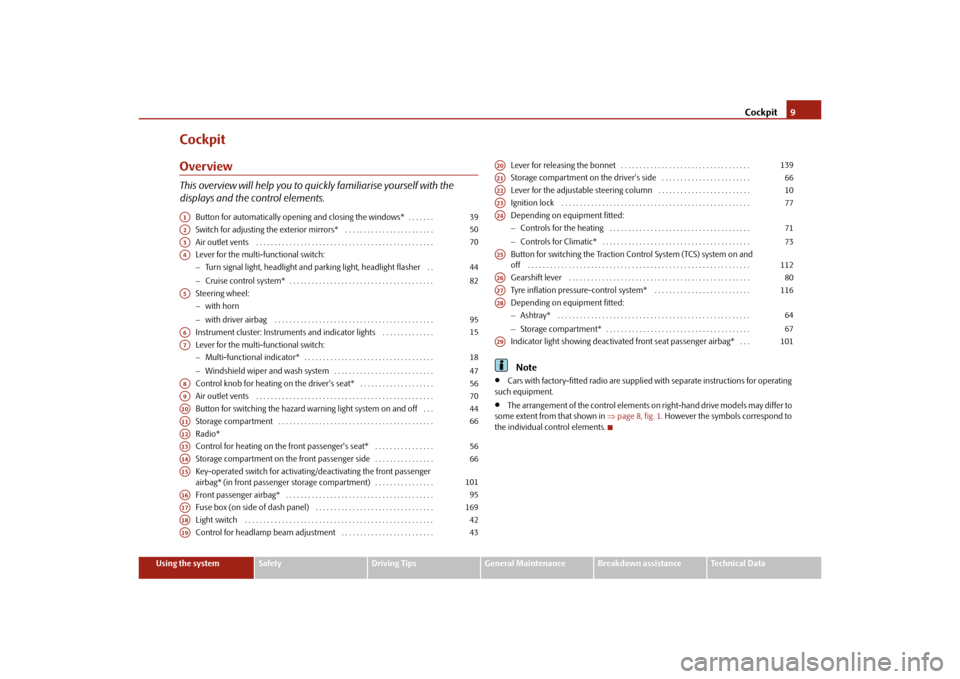
CockpitOverviewThis overview will help you to quic kly familiarise yourself with the
displays and the control elements.
Button for automatically opening and closing the windows* . . . . . . .
Switch for adjusting the exterior mirrors* . . . . . . . . . . . . . . . . . . . . . . . .
Air outlet vents . . . . . . . . . . . . . . . . . . . . . . . . . . . . . . . . . . . . . . . . . . . . . . . .
Lever for the multi-functional switch:
Turn signal light, headlight and parking light, headlight flasher . .
Cruise control system* . . . . . . . . . . . . . . . . . . . . . . . . . . . . . . . . . . . . . . .
Steering wheel:
with horn
with driver airbag . . . . . . . . . . . . . . . . . . . . . . . . . . . . . . . . . . . . . . . . . . .
Instrument cluster: Instruments and indicator lights . . . . . . . . . . . . . .
Lever for the multi-functional switch:
Multi-functional indicator* . . . . . . . . . . . . . . . . . . . . . . . . . . . . . . . . . . .
Windshield wiper and wash system . . . . . . . . . . . . . . . . . . . . . . . . . . .
Control knob for heating on the driver's seat* . . . . . . . . . . . . . . . . . . . .
Air outlet vents . . . . . . . . . . . . . . . . . . . . . . . . . . . . . . . . . . . . . . . . . . . . . . . .
Button for switching the hazard warning light system on and off . . .
Storage compartment . . . . . . . . . . . . . . . . . . . . . . . . . . . . . . . . . . . . . . . . . .
Radio*
Control for heating on the front passenger's seat* . . . . . . . . . . . . . . . .
Storage compartment on the front passenger side . . . . . . . . . . . . . . . .
Key-operated switch for activating/deactivating the front passenger
airbag* (in front passenger storage compartment) . . . . . . . . . . . . . . . .
Front passenger airbag* . . . . . . . . . . . . . . . . . . . . . . . . . . . . . . . . . . . . . . . .
Fuse box (on side of dash panel) . . . . . . . . . . . . . . . . . . . . . . . . . . . . . . . .
Light switch . . . . . . . . . . . . . . . . . . . . . . . . . . . . . . . . . . . . . . . . . . . . . . . . . . .
Control for headlamp beam adjustment . . . . . . . . . . . . . . . . . . . . . . . . . Lever for releasing the bonnet . . . . . . . . . . . . . . . . . . . . . . . . . . . . . . . . . . .
Storage compartment on the driver's side . . . . . . . . . . . . . . . . . . . . . . . .
Lever for the adjustable steering column . . . . . . . . . . . . . . . . . . . . . . . . .
Ignition lock . . . . . . . . . . . . . . . . . . . . . . . . . . . . . . . . . . . . . . . . . . . . . . . . . . .
Depending on equipment fitted:
Controls for the heating . . . . . . . . . . . . . . . . . . . . . . . . . . . . . . . . . . . . . .
Controls for Climatic* . . . . . . . . . . . . . . . . . . . . . . . . . . . . . . . . . . . . . . . .
Button for switching the Traction Control System (TCS) system on and
off . . . . . . . . . . . . . . . . . . . . . . . . . . . . . . . . . . . . . . . . . . . . . . . . . . . . . . . . . . . .
Gearshift lever . . . . . . . . . . . . . . . . . . . . . . . . . . . . . . . . . . . . . . . . . . . . . . . . .
Tyre inflation pressure-control system* . . . . . . . . . . . . . . . . . . . . . . . . . .
Depending on equipment fitted:
Ashtray* . . . . . . . . . . . . . . . . . . . . . . . . . . . . . . . . . . . . . . . . . . . . . . . . . . . .
Storage compartment* . . . . . . . . . . . . . . . . . . . . . . . . . . . . . . . . . . . . . . .
Indicator light showing deactivated front seat passenger airbag* . . .
Note
Cars with factory-fitted radio are supplied with separate instructions for operating
such equipment.
The arrangement of the control elements on right-hand drive models may differ to
some extent from that shown in page 8, fig. 1 . However the symbols correspond to
the individual control elements.
A1
39
A2
50
A3
70
A4
4482
A5
95
A6
15
A7
1847
A8
56
A9
70
A10
44
A11
66
A12A13
56
A14
66
A15
101
A16
95
A17
169
A18
42
A19
43
A20
139
A21
66
A22
10
A23
77
A24
7173
A25
112
A26
80
A27
116
A28
6467
A29
101
s2bs.2.book Page 9 Monday, September 27, 2010 9:53 AM
Page 12 of 199

The brief instruction11
Using the system
Safety
Driving Tips
General Maintenance
Breakdown assistance
Technical Data
Seat belt height adjuster– Move the height adjuster in the desired direction up or down fig. 4 .
– Then pull firmly on the belt to ensure that the seat belt height adjuster has correctly
locked in place.
Further information page 91, “Seat belt height adjuster”.
WARNING
Adjust the height of the belt in such a way that the shoulder part of the belt is
positioned approximately across the middle of your shoulder - on no account
across your neck!Adjusting the front seats
Adjusting a seat in a forward/back direction
Adjusting height of seat*
Adjust the angle of the seat backrest
Adjusting lumbar support*
Further information page 52, “Adjusting the front seats”.
WARNING
Only adjust the driver seat when the ve hicle is stationary - risk of injury!Electric exterior mirror adjustment*Further information page 50, “Exterior mirror”.
Fig. 4 Front seat: Seat belt height
adjusterFig. 5 Controls at seat
Heating of the external mirror
Adjusting left and right exterior mirrors simultaneously
Adjusting the right-hand exterior mirror
Switching off operating control
A1A2A3A4
Fig. 6 Inner part of door: Rotary knob
s2bs.2.book Page 11 Monday, September 27, 2010 9:53 AM
Page 48 of 199
Lights and Visibility47
Using the system
Safety
Driving Tips
General Maintenance
Breakdown assistance
Technical Data
If the on-board voltage drops, the rear window heater is switched off automatically,
in order to provide sufficient electrical energy for the engine control.
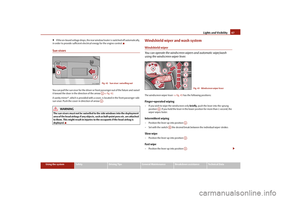
Sun visorsYou can pull the sun visor for the driver or front passenger out of the fixture and swivel
it toward the door in the direction of the arrow fig. 42 .
A vanity mirror*, which is provided with a cover, is located in the front passenger side
sun visor. Push the cover in direction of arrow .
WARNING
The sun visors must not be swivelled to the side windows into the deployment
area of the head airbags if any objects, such as ball-point pens etc. are attached
to them. This might result in injuries to the occupants if the head airbag is
deployed.
Windshield wiper and wash systemWindshield wiper
You can operate the windscreen wipers and automatic wipe/wash
using the windscreen wiper lever.The windscreen wiper lever fig. 43 has the following positions:Finger-operated wiping– If you wish to wipe the windscreen only briefly, push the lever into the sprung
position . If you hold the lever in the lower position for more than 1 second, the
wiper wipes faster.Intermittent wiping– Position the lever up into position .
– Set with the switch the desired brea k between the individual wiper strokesSlow wipe– Position the lever up into position .Fast wipe– Position the lever up into position .
Fig. 42 Sun visor: swivelling outA1A2
Fig. 43 Windscreen wiper lever
A4
A1
AA
A2A3
s2bs.2.book Page 47 Monday, September 27, 2010 9:53 AM
Page 51 of 199

Lights and Visibility
50
Replacing the wiper blade on the rear window wiperTaking off the wiper blade – Fold windscreen wiper arm out from the windscreen and position the wiper blade
at right angles to the wiper arm fig. 45 .
– Hold the window wiper arm at the top end with one hand.
– With the other hand unlock the locking button in the direction of arrow and remove the wiper blade.Attaching a wiper blade– Position the wiper blade onto the wiper arm and lock the locking button .
– Check whether the wiper blade is correctly attached.
The same remarks apply here as for page 49, “Replacing wiper blades for the wind-
screen wipers”.Rear-view mirrorManual dimming interior rear-view mirrorBasic setting– Pull the lever on the bottom edge of the mirror forward.
Dimming mirror– Pull the lever on the bottom edge of the mirror back.Exterior mirror
You can adjust the exterior mirrors electrically*.The exterior mirror heater only operates when the engine is running and up to an
outside temperature of +20 °C. Heating of the external mirror – Turn the rotary knob to position
fig. 46 .
Adjusting left and right exterior mirrors simultaneously– Turn the rotary knob to position
. The movement of the mirror surface is identical
to the movement of the rotary knob.
Adjusting the right-hand exterior mirror– Turn the rotary knob to position
. The movement of the mirror surface is identical
to the movement of the rotary knob.
Switching off operating control– Turn the rotary knob to position
.
Fig. 45 Wiper blade for rear windowAA
AA
Fig. 46 Inner part of door: Rotary knob
s2bs.2.book Page 50 Monday, September 27, 2010 9:53 AM
Page 52 of 199
Lights and Visibility51
Using the system
Safety
Driving Tips
General Maintenance
Breakdown assistance
Technical Data
WARNING
Convex (curved outward) or spherical (differently curved) exterior mirrors
increase the vision field. They do, howe ver, make objects appear smaller in the
mirror. These mirrors are only of limited use, therefore, for estimating distances
to the following vehicles.
Use whenever possible the interior rear mirror, for estimating the distances
to the following vehicles.Note
Do not touch the surfaces of the exterior mirrors if the exterior mirror heater is
switched on.
You can set the exterior mirr ors by hand, if the power setting function fails at any
time by pressing on the edge of the mirror surface.
Contact your specialist garage if a fault ex ists with the power setting of the exterior
mirrors.
s2bs.2.book Page 51 Monday, September 27, 2010 9:53 AM
Page 87 of 199
Passive Safety
86
Ensure that all the windows offer a good visibility to the outside.
Safely attach the items of luggage page 57, “Loading the luggage compartment”.
Ensure that no objects can obstruct the pedal.
Adjust the mirror, the front seat and the head restraint to match your body size.
Point out to your occupants that the head restraints must be adjusted to match
their body size.
Protect the children in suitable child seats with correctly fastened seat belts
page 103, “Transporting children safely”.
Adopt the correct seated position page 86, “Correct seated position”. Also
inform your occupants to adopt the correct seated position.
Fasten the seat belt correctly. Also inform your occupants to properly fasten the
seat belts page 91, “How are seat belts correctly fastened?”.
What influences the driving safety?
The driving safety is primarily determined by the style of driving and the
personal behaviour of all the occupants.The driver is fully responsible for himself an d his occupants. If your driving safety is
effected, you place yourself and the oncomi ng traffic at risk. Please refer to the
following guidelines.
Do not get distracted from concentrating on the traffic situation, e.g. by your occu-
pants or mobile phone calls.
Never drive when your driving ability is impaired, e.g. through medication, alcohol,
drugs.
Keep to the traffic regulations and the permissible speed limit.
Adjust the driving speed at all times to the road condition as well as to the traffic
and weather conditions.
Take regular breaks on long journe ys - at the latest every two hours.
Correct seated positionCorrect seated position for the driver
Correct seated position for the driver is important for safe and relaxed
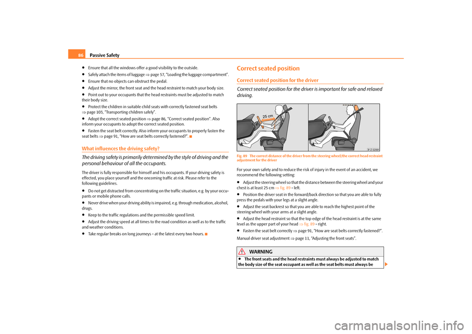
driving.Fig. 89 The correct distance of the driver fr om the steering wheel/the correct head restraint
adjustment for the driverFor your own safety and to reduce the risk of injury in the event of an accident, we
recommend the following setting:
Adjust the steering wheel so that the distance between the steering wheel and your
chest is at least 25 cm fig. 89 - left.
Position the driver seat in the forward/back direction so that you are able to fully
press the pedals with your legs at a slight angle.
Adjust the seat backrest so that you are able to reach the highest point of the
steering wheel with your arms at a slight angle.
Adjust the head restraint so that the top edge of the head restraint is at the same
level as the upper part of your head fig. 89 - right.
Fasten the seat belt correctly page 91, “How are seat belts correctly fastened?”.
Manual driver se at adjustment page 11, “Adjusting the front seats”.
WARNING
The front seats and the head restraints must always be adjusted to match
the body size of the seat occupant as well as the seat belts must always be
s2bs.2.book Page 86 Monday, September 27, 2010 9:53 AM
Page 126 of 199

Towing a trailer125
Using the system
Safety
Driving Tips
General Maintenance
Breakdown assistance
Technical Data
Towing a trailerTo w i n g a t r a i l e rTechnical requirementsYour vehicle is designed primarily for tr ansporting persons and luggage. It can,
however, also be used for towing a traile r - provided certain technical equipment is
fitted.
If your vehicle has already been supplied with a factory-fitted towing device then
everything that is necessary for towing a trai ler in technical terms, and in terms of the
law, has already been taken into account.
Your vehicle is fitted with a 13-pin power socket for the electrical connection between
the vehicle and trailer. If the trailer which you wish to tow has a 7-pin connector, you
can use a suitable adapter
6) from Škoda original accessories.
This work must be carried out in accordance with the manufacturer's specifications if
a towing device is retrofitted.
Authorised Škoda Service Partners can provid e information about retrofitting a towing
device and for any necessary modifications to the cooling system.
WARNING
We recommend that you have the towing device from Škoda original accesso-
ries installed by an authorised Škoda Service Partner. He is familiar with all the
relevant details relating to retrofitting such equipment. There is a risk of an
accident if the towing device is not properly fitted!General MaintenanceTrailer load
The permissible trailer load must on no account be exceeded. You can negotiate appropriately steeper inclin
es and descents if you do not make full
use of the permissible trailer load.
The trailer loads specified only apply for altitudes up to 1 000 metres above mean sea
level. The fact that the engine power outp ut drops with increasing height due to a
lowering of air pressure and thus the abil ity to climb, means that the towed weight
must be reduced by 10 % for every further increase of 1 000 metres in height above
sea level. The towed weight is the weight of the (laden) vehicle and the (laden) trailer
together. One should take this into account before driving up to higher altitudes.
The trailer and drawbar load information on the type plate of the towing device
are merely test data for the towing device The data relating to your vehicle, which
is often less than this test data, can be found in your vehicle registration docu-
ments.
Distribution of the load
Distribute the load in the trailer in such a way that any heavy items are located as close
as possible to the axle. Secure th e items to prevent them slipping.
Tyre inflation pressure
Select the tyre inflation pressure on yo ur vehicle for that of “fully laden”, page 151.
The inflation pressure of the tyres fitted to the trailer adjust in accordance with the
manufacturer's recommendation.
Exterior mirrors
You have to have additional exterior mirrors fitted if you are not able to see the traffic
behind the trailer with the standard rear-view mirrors. Both exterior mirrors should be
attached to folding arms. Adjust the mirrors so that they provide you with an adequate
field of view to the rear.
Headlights
Before starting off with a hitched trailer, al so check the setting of the headlights. Alter
the setting as necessary with the aid of the headlight beam adjuster page 43.
Detachable ball head
The ball rod is detachable on vehicles whic h feature a factory-fitted towing device.6)In some countries the adapter is supplied with the towing device.
s2bs.2.book Page 125 Monday, September 27, 2010 9:53 AM
Page 132 of 199

Taking care of your vehicle and cleaning the vehicle131
Using the system
Safety
Driving Tips
General Maintenance
Breakdown assistance
Technical Data
A new layer of a high-quality
hard wax polish can be applied to the clean bodywork
after it has dried thoroughly. Even if you use a wax preserver regularly we still recom-
mend that you treat the paintwork of the ve hicle at least twice a year with hard wax.
Caution
Never apply wax to the windows.PolishingPolishing is only necessary if the paintwork of your vehicle has become unattractive
and if it is no longer possible to achieve a gloss with wax preservers.
You must treat the paintwork with a wax pr eserver if the polish you use does not
contain any preserving elements page 130.
We recommend using a preserva tive from Škoda genuine accessories offered by your
Škoda dealer.
Caution
You must not treat mat painted parts or plas tic with polishing products or hard wax.
Do not polish the paintwork of the vehicle in a dusty environment, otherwise the
paintwork can be scratched.
Chrome partsFirst clean the chrome parts with a damp cl oth and then polish them with a soft, dry
cloth. If it does not prove to be adequate, use a chrome care product from Škoda orig-
inal accessories.
Caution
Do not polish the chrome parts in a du sty environment, otherwise they can be
scratched.
Paint damageSlight damage to paintwork such as scratches, scuffs or traces of chip damage must be
touched up immediately with paint (Škoda painting pen) before any corrosion can
result. You can of course have this work ca rried out by authorised Škoda Service Part-
ners.
The authorised Škoda Service Partners have a range of matching touch-up pens or
spray cans available in the colour of your vehicle.
The paint number of the original paintwork of your vehicle is indicated on the vehicle
data sticker page 179.
Any corrosion which has already have formed must be removed thoroughly. Apply a
corrosion protection primer and then the paint to the affected point. You can of
course have this work carried out by authorised Škoda Service Partners.Plastic partsExternal plastic parts are cleaned by norm al washing. Plastic parts and synthetic
leather can also be treated with special solvent-free plastic cleaning agents if a
damp cloth is not sufficient. Paint care pr oducts are not suitable for plastic parts.
Caution
Solvent-free cleaners attack the material and can damage it.WindowsOnly use a plastic ice scraper for removing snow and ice from the windows and
mirrors. You should not move the ice scraper forward and backward but in one direc-
tion on the window which you are cleaning in order to avoid any damage to the surface
of the glass.
You can best remove residues of rubber, oil, grease, wax or silicone by using a special
window cleaner or a special silicone remover.
You should also clean the windows regularly from the inside.
s2bs.2.book Page 131 Monday, September 27, 2010 9:53 AM
Page 172 of 199
Fuses and light bulbs171
Using the system
Safety
Driving Tips
General Maintenance
Breakdown assistance
Technical Data
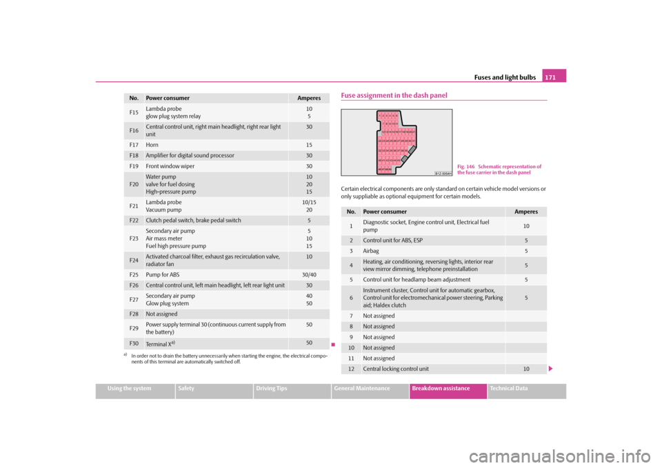
Fuse assignment in the dash panelCertain electrical components are only stan dard on certain vehicle model versions or
only suppliable as optional equipment for certain models.
F15
Lambda probe
glow plug system relay
10
5
F16
Central control unit, right main headlight, right rear light
unit
30
F17
Horn
15
F18
Amplifier for digital sound processor
30
F19
Front window wiper
30
F20
Wa te r pump
valve for fuel dosing
High-pressure pump
10
20
15
F21
Lambda probe
Vacuum pump
10/15 20
F22
Clutch pedal switch, brake pedal switch
5
F23
Secondary air pump
Air mass meter
Fuel high pressure pump
5
10
15
F24
Activated charcoal filter, exha ust gas recirculation valve,
radiator fan
10
F25
Pump for ABS
30/40
F26
Central control unit, left main headlight, left rear light unit
30
F27
Secondary air pump
Glow plug system
40
50
F28
Not assigned
F29
Power supply terminal 30 (con tinuous current supply from
the battery)
50
F30
Te r m i n a l X
a)
50
a)In order not to drain the battery unnecessarily wh en starting the engine, the electrical compo-
nents of this terminal are automatically switched off.No.
Power consumer
Amperes
No.
Power consumer
Amperes
1
Diagnostic socket, Engine control unit, Electrical fuel
pump
10
2
Control unit for ABS, ESP
5
3
Airbag
5
4
Heating, air conditioning, reve rsing lights, interior rear
view mirror dimming, te lephone preinstallation
5
5
Control unit for headlamp beam adjustment
5
6
Instrument cluster, Control unit for automatic gearbox,
Control unit for electromechanical power steering, Parking
aid; Haldex clutch
5
7
Not assigned
8
Not assigned
9
Not assigned
10
Not assigned
11
Not assigned
12
Central locking control unit
10
Fig. 146 Schematic representation of
the fuse carrier in the dash panel
s2bs.2.book Page 171 Monday, September 27, 2010 9:53 AM