tow SKODA RAPID 2012 1.G User Guide
[x] Cancel search | Manufacturer: SKODA, Model Year: 2012, Model line: RAPID, Model: SKODA RAPID 2012 1.GPages: 180, PDF Size: 4.36 MB
Page 43 of 180
›
Release the lever. The washer system stops and the wiper continues for anoth-
er 1 to 3 wiper strokes (depending on the duration of the spraying process). The
lever will stay in position after releasing it 6
.
Switching windscreen wipers off
› Move the lever back into the home position 0
» Fig. 28
. ÐHeadlight cleaning system
First read and observe the introductory information and safety warn-
ings on page 39.
When the low beam or main beam are switched on, and the windscreen wiper
lever is pulled into the position 5
» Fig. 28
on page
40, the headlights are
sprayed briefly. To clean the headlights, the windshield is also sprayed after every
ten squirts.
You should remove stubborn dirt (such as insect residues) from the headlight len-
ses at regular intervals, for example when refuelling. The following guidelines
must be observed » page 120, Headlight lenses.
To ensure the proper operation of the cleaning system during the winter, any
snow should be removed from the washer nozzle fixtures and ice should be
cleared with a de-icing spray. CAUTION
Never remove the nozzles from the headlight cleaning system by hand – risk of
damage! ÐReplacing the front windscreen wiper blades
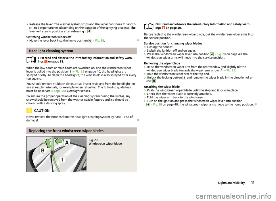
Fig. 29
Windscreen wiper blade
ä
First read and observe the introductory information and safety warn-
ings on page 39.
Before replacing the windscreen wiper blade, put the windscreen wiper arms into
the service position.
Service position for changing wiper blades
› Closing the bonnet.
› Switch the ignition off and on again.
› Press the windscreen wiper lever into position 4
» Fig. 28
on page
40, the
windscreen wiper arms will move into the service position.
Removing the wiper blade
› Raise the windscreen wiper arm from the rear window and slightly tilt the
windscreen wiper blade towards the wiper arm, arrow A
»
Fig. 29
.
› Hold the windscreen wiper arm at the top end.
› Unlock the locking button 1
and remove the wiper blade in the direction of ar-
row B
.
Attaching the wiper blade
› Push the windscreen wiper blade until the stop and it locks in place.
› Check that the wiper blade is correctly attached.
› Fold the wiper arm back to the windscreen.
› Turn on the ignition and press the windscreen wiper lever into position 4
» Fig. 28 on page 40
, the windscreen wiper arms move to the home position. Ð
ä
41
Lights and visibility
Page 44 of 180
Replacing the rear window glass wiper blades
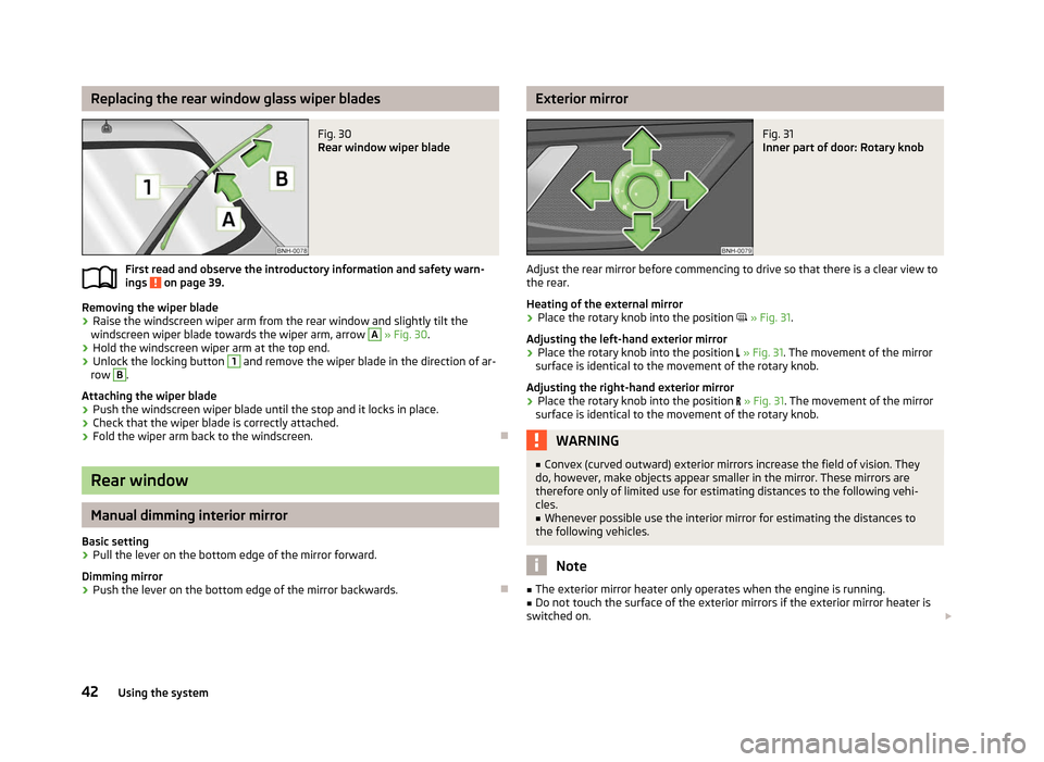
Fig. 30
Rear window wiper blade
First read and observe the introductory information and safety warn-
ings on page 39.
Removing the wiper blade
› Raise the windscreen wiper arm from the rear window and slightly tilt the
windscreen wiper blade towards the wiper arm, arrow A
» Fig. 30
.
› Hold the windscreen wiper arm at the top end.
› Unlock the locking button 1
and remove the wiper blade in the direction of ar-
row B
.
Attaching the wiper blade
› Push the windscreen wiper blade until the stop and it locks in place.
› Check that the wiper blade is correctly attached.
› Fold the wiper arm back to the windscreen. ÐRear window
Manual dimming interior mirror
Basic setting
› Pull the lever on the bottom edge of the mirror forward.
Dimming mirror
› Push the lever on the bottom edge of the mirror backwards. Ð
ä Exterior mirror
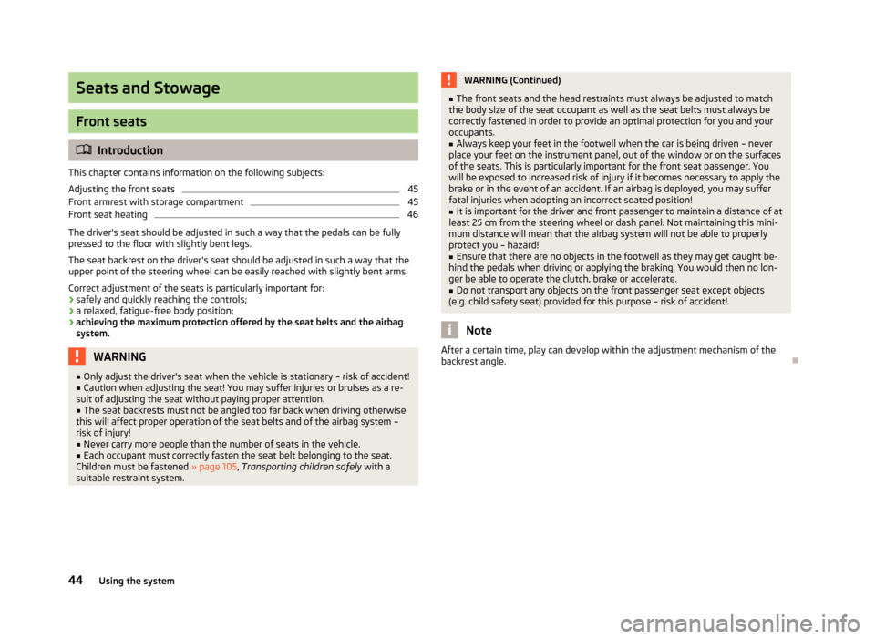
Fig. 31
Inner part of door: Rotary knob
Adjust the rear mirror before commencing to drive so that there is a clear view to
the rear.
Heating of the external mirror
› Place the rotary knob into the position
» Fig. 31.
Adjusting the left-hand exterior mirror
› Place the rotary knob into the position
» Fig. 31. The movement of the mirror
surface is identical to the movement of the rotary knob.
Adjusting the right-hand exterior mirror
› Place the rotary knob into the position
» Fig. 31. The movement of the mirror
surface is identical to the movement of the rotary knob. WARNING
■ Convex (curved outward) exterior mirrors increase the field of vision. They
do, however, make objects appear smaller in the mirror. These mirrors are
therefore only of limited use for estimating distances to the following vehi-
cles.
■ Whenever possible use the interior mirror for estimating the distances to
the following vehicles. Note
■ The exterior mirror heater only operates when the engine is running.
■ Do not touch the surface of the exterior mirrors if the exterior mirror heater is
switched on. £
42 Using the system
Page 46 of 180
Seats and Stowage
Front seats
ä
Introduction
This chapter contains information on the following subjects:
Adjusting the front seats 45
Front armrest with storage compartment 45
Front seat heating 46
The driver's seat should be adjusted in such a way that the pedals can be fully
pressed to the floor with slightly bent legs.
The seat backrest on the driver's seat should be adjusted in such a way that the
upper point of the steering wheel can be easily reached with slightly bent arms.
Correct adjustment of the seats is particularly important for:
› safely and quickly reaching the controls;
› a relaxed, fatigue-free body position;
› achieving the maximum protection offered by the seat belts and the airbag
system. WARNING
■ Only adjust the driver's seat when the vehicle is stationary – risk of accident!
■ Caution when adjusting the seat! You may suffer injuries or bruises as a re-
sult of adjusting the seat without paying proper attention.
■ The seat backrests must not be angled too far back when driving otherwise
this will affect proper operation of the seat belts and of the airbag system –
risk of injury!
■ Never carry more people than the number of seats in the vehicle.
■ Each occupant must correctly fasten the seat belt belonging to the seat.
Children must be fastened » page 105, Transporting children safely with a
suitable restraint system. WARNING (Continued)
■ The front seats and the head restraints must always be adjusted to match
the body size of the seat occupant as well as the seat belts must always be
correctly fastened in order to provide an optimal protection for you and your
occupants.
■ Always keep your feet in the footwell when the car is being driven – never
place your feet on the instrument panel, out of the window or on the surfaces
of the seats. This is particularly important for the front seat passenger. You
will be exposed to increased risk of injury if it becomes necessary to apply the
brake or in the event of an accident. If an airbag is deployed, you may suffer
fatal injuries when adopting an incorrect seated position!
■ It is important for the driver and front passenger to maintain a distance of at
least 25 cm from the steering wheel or dash panel. Not maintaining this mini-
mum distance will mean that the airbag system will not be able to properly
protect you – hazard!
■ Ensure that there are no objects in the footwell as they may get caught be-
hind the pedals when driving or applying the braking. You would then no lon-
ger be able to operate the clutch, brake or accelerate. ■ Do not transport any objects on the front passenger seat except objects
(e.g. child safety seat) provided for this purpose – risk of accident! Note
After a certain time, play can develop within the adjustment mechanism of the
backrest angle. Ð
44 Using the system
Page 47 of 180
Adjusting the front seats
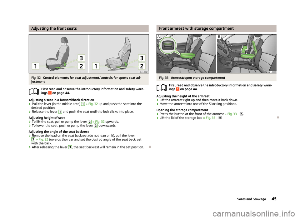
Fig. 32
Control elements for seat adjustment/controls for sports seat ad-
justment
First read and observe the introductory information and safety warn-
ings on page 44.
Adjusting a seat in a forward/back direction
›
Pull the lever (in the middle area) 1
» Fig. 32
up and push the seat into the
desired position.
› Release the lever 1
and push the seat until the lock clicks into place.
Adjusting height of seat
› To lift the seat, pull or pump the lever 2
» Fig. 32
upwards.
› To lower the seat, push or pump the lever 2
downwards.
Adjusting the angle of the seat backrest
› Remove the load on the seat backrest (do not lean on it), pull the lever 3
» Fig. 32 towards the rear and set the desired angle of the seat backrest
with the back.
› After releasing the lever 3
, the seat backrest will remain in the set position.
Ð
ä Front armrest with storage compartment
Fig. 33
Armrest/open storage compartment
First read and observe the introductory information and safety warn-
ings on page 44.
Adjusting the height of the armrest
›
Lift the armrest right up and then move it back down.
› Move the armrest into one of the 5 locking positions.
Opening the storage compartment
› Press the button at the front of the armrest
» Fig. 33 – .
› Lift the lid of the storage box
» Fig. 33 – . Ð
ä
45
Seats and Stowage
Page 49 of 180
Removing and installing head restraints
›
Pull the head restraint out of the seat backrest as far as the stop.
› Press the safety button A
» Fig. 35 and pull out the head restraint.
› To re-insert the head restraint, push it far enough down into the seat backrest
until the locking button clicks into place.
Removing and installing rear head restraints
› Pull the head restraint out of the seat backrest as far as the stop.
› Press the locking button 1
» Fig. 35, simultaneously press the locking button
into the opening 2
using a flat screwdriver with a width of maximum 5 mm and
pull out the head restraint.
› To re-insert the head restraint, push it far enough down into the seat backrest
until the locking button clicks into place.
Best protection is achieved if the top edge of the head restraint is at the same
level as the upper part of your head.
The head restraints must be adjusted to match the size of the seat occupant. Cor-
rectly adjusted head restraints together with the seat belts offer effective protec-
tion for the occupants » page 92.WARNING
■ The head restraints must be correctly adjusted in order to offer effective
protection for the occupants in the event of an accident.
■ Never drive with the head restraints removed – risk of injury!
■ If the rear seats are occupied, the rear head restraint must not be in the
lower position. Ð Rear seats
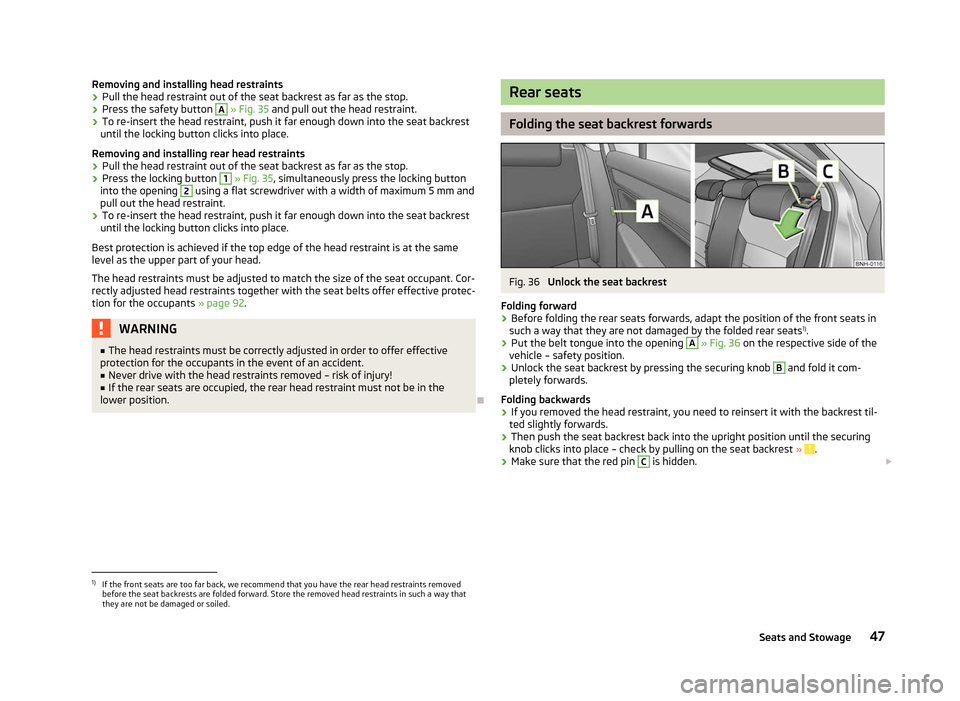
Folding the seat backrest forwards
Fig. 36
Unlock the seat backrest
Folding forward
› Before folding the rear seats forwards, adapt the position of the front seats in
such a way that they are not damaged by the folded rear seats 1)
.
› Put the belt tongue into the opening A
» Fig. 36
on the respective side of the
vehicle – safety position.
› Unlock the seat backrest by pressing the securing knob B
and fold it com-
pletely forwards.
Folding backwards
› If you removed the head restraint, you need to reinsert it with the backrest til-
ted slightly forwards.
› Then push the seat backrest back into the upright position until the securing
knob clicks into place – check by pulling on the seat backrest » .
› Make sure that the red pin C
is hidden.
£1)
If the front seats are too far back, we recommend that you have the rear head restraints removed
before the seat backrests are folded forward. Store the removed head restraints in such a way that
they are not be damaged or soiled.
47
Seats and Stowage
Page 51 of 180
WARNING (Continued)
■ The items carried in the boot must be stored in such a way that no objects
are able to slip forward if any sudden driving or braking manoeuvres are un-
dertaken – risk of injury!
■ When transporting fastened objects which are sharp and dangerous in the
boot that has been enlarged by folding the rear seats forward, ensure the
safety of the passengers transported on the other rear seats » page 93, Cor-
rect seated position for the occupants on the rear seats .
■ If the rear seat next to the folded forward seat is occupied, ensure maxi-
mum safety, e.g. by placing the goods to be transported in such a way that the
seat is prevented from folding back in case of a rear collision.
■ Never drive with the boot lid fully opened or slightly ajar otherwise exhaust
gases may get into the interior of the vehicle – risk of poisoning!
■ Under no circumstances, should the permissible axle loads and permissible
gross weight of the vehicle be exceeded – risk of accident! ■ Never transport people in the boot! CAUTION
Please ensure that the heating elements for the rear window heater are not dam-
aged as a result of abrasive objects. Note
Tyre pressure must be adjusted to the load » page 138, Service life of tyres .Ð Boot light
First read and observe the introductory information and safety warn-
ings on page 48.
The light comes on automatically when the boot lid is opened. If the lid remains
open for more than about 10
minutes, the boot light switches off automatically. ÐClass N1 vehicles
First read and observe the introductory information and safety warn-
ings on page 48.ä
ä On class N1 vehicles, which are not fitted with a protective grille, a lashing set
which complies with the standard EN
12195 (1 - 4) must be used for fastening the
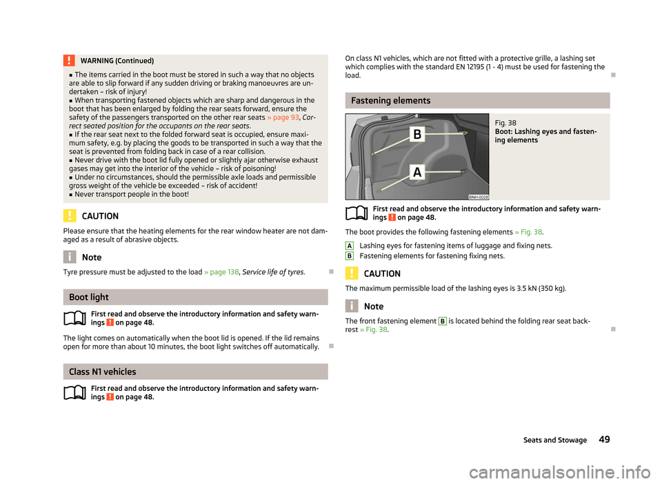
load. Ð Fastening elements
Fig. 38
Boot: Lashing eyes and fasten-
ing elements
First read and observe the introductory information and safety warn-
ings on page 48.
The boot provides the following fastening elements
»
Fig. 38.
Lashing eyes for fastening items of luggage and fixing nets.
Fastening elements for fastening fixing nets. CAUTION
The maximum permissible load of the lashing eyes is 3.5 kN (350 kg). Note
The front fastening element B
is located behind the folding rear seat back-
rest » Fig. 38. Ð
ä A
B
49
Seats and Stowage
Page 53 of 180
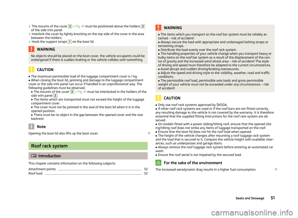
›
The mounts of the cover 3
» Fig. 41 must be positioned above the holders 2
of the side trim panel.
› Interlock the cover by lightly knocking on the top side of the cover in the area
between the holders.
› Hook the support straps 1
on the boot lid.
WARNING
No objects should be placed on the boot cover, the vehicle occupants could be
endangered if there is sudden braking or the vehicle collides with something. CAUTION
■ The maximum permissible load of the luggage compartment cover is 1 kg.
■ When closing the boot lid, jamming and damage to the luggage compartment
cover or the side trim panel can occur if handled in an unprofessional way. The
following guidelines must be observed. ■ The mounts of the cover 3
» Fig. 41 must be interlocked in the holders of the
side trim panel 2
.
■ The items which are transported must not exceed the height of the luggage
compartment cover. ■ The cover must not be jammed in the seal of the boot lid when it is in the
opened position.
■ There must be no object in the gap between the opened cover and the rear
backrest. Note
Opening the boot lid also lifts up the boot cover. ÐRoof rack system
ä
Introduction
This chapter contains information on the following subjects:
Attachment points 52
Roof load 52 WARNING
■ The items which you transport on the roof bar system must be reliably at-
tached – risk of accident!
■ Always secure the load with appropriate and undamaged lashing straps or
tensioning straps.
■ Distribute the load evenly over the roof rack system.
■ The handling properties of your vehicle change when you transport heavy or
bulky items on the roof bar system as a result of the displacement of the cen-
tre of gravity and the increased wind attack area – risk of accident! The style
of driving and speed must therefore be adapted to the current circumstances. ■ Avoid abrupt and sudden driving/braking manoeuvres.
■ Adjust the speed and driving style to the visibility, weather, road and traffic
conditions. ■ The permissible roof load, permissible axle loads and gross permissible
weight of your vehicle must not be exceeded under any circumstances – risk
of accident! CAUTION
■ Only use roof rack systems approved by
ŠKODA.
■ If other roof rack systems are used or if the roof bars are not fitted correctly,
any resulting damage to the vehicle is not covered by the warranty. It is therefore
essential that the supplied fitting instructions for the roof rack system are ob-
served.
■ On models fitted with a power sliding/tilting roof, ensure that the opened slid-
ing/tilting roof does not strike any items of luggage transported on the roof. ■ Ensure that the boot lid does not hit the roof load when opened.
■ The height of the vehicle changes after mounting a roof luggage rack system
and the load that is secured to it. Compare the vehicle height with available clear-
ances, such as underpasses and garage doors.
■ Always remove the roof luggage rack system before entering an automated car
wash. ■ Ensure the roof aerial is not impaired by the secured load. For the sake of the environment
The increased aerodynamic drag results in a higher fuel consumption. Ð
51
Seats and Stowage
Page 55 of 180
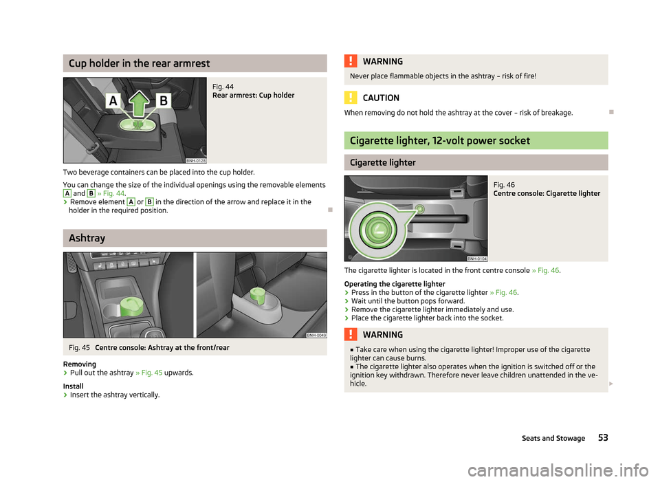
Cup holder in the rear armrest
Fig. 44
Rear armrest: Cup holder
Two beverage containers can be placed into the cup holder.
You can change the size of the individual openings using the removable elements A
and B
» Fig. 44.
› Remove element A
or B
in the direction of the arrow and replace it in the
holder in the required position. ÐAshtray
Fig. 45
Centre console: Ashtray at the front/rear
Removing › Pull out the ashtray
» Fig. 45 upwards.
Install
› Insert the ashtray vertically. WARNING
Never place flammable objects in the ashtray – risk of fire! CAUTION
When removing do not hold the ashtray at the cover – risk of breakage. Ð Cigarette lighter, 12-volt power socket
Cigarette lighter
Fig. 46
Centre console: Cigarette lighter
The cigarette lighter is located in the front centre console » Fig. 46.
Operating the cigarette lighter
› Press in the button of the cigarette lighter
» Fig. 46.
› Wait until the button pops forward.
› Remove the cigarette lighter immediately and use.
› Place the cigarette lighter back into the socket. WARNING
■ Take care when using the cigarette lighter! Improper use of the cigarette
lighter can cause burns. ■ The cigarette lighter also operates when the ignition is switched off or the
ignition key withdrawn. Therefore never leave children unattended in the ve-
hicle. £
53
Seats and Stowage
Page 57 of 180
WARNING
■ Do not place anything on the dash panel. These objects might slide or fall
down when driving and may distract you from concentrating on the traffic –
risk of accident!
■ When driving, ensure that no objects from the centre console or from other
storage compartments can get into the driver's footwell. You would then no
longer be able to apply the brakes, operate the clutch or accelerator – risk of
accident! ÐStorage compartment on the front passenger side
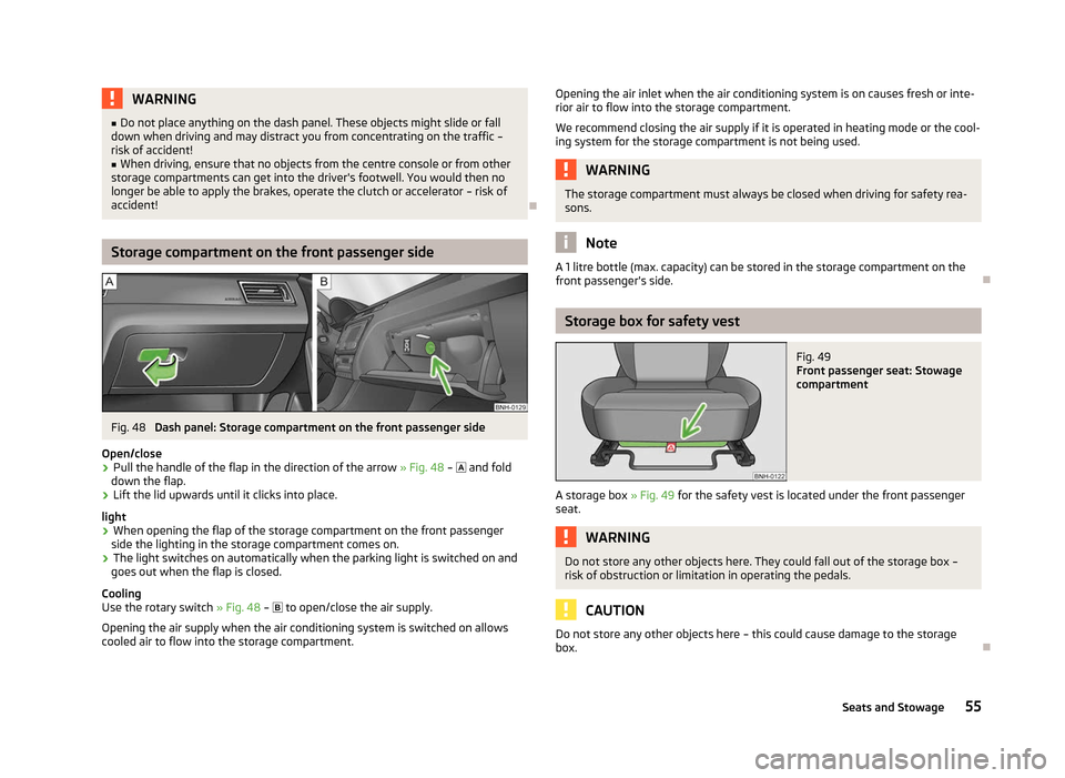
Fig. 48
Dash panel: Storage compartment on the front passenger side
Open/close
› Pull the handle of the flap in the direction of the arrow
» Fig. 48 – and fold
down the flap.
› Lift the lid upwards until it clicks into place.
light
› When opening the flap of the storage compartment on the front passenger
side the lighting in the storage compartment comes on.
› The light switches on automatically when the parking light is switched on and
goes out when the flap is closed.
Cooling
Use the rotary switch » Fig. 48 –
to open/close the air supply.
Opening the air supply when the air conditioning system is switched on allows
cooled air to flow into the storage compartment. Opening the air inlet when the air conditioning system is on causes fresh or inte-
rior air to flow into the storage compartment.
We recommend closing the air supply if it is operated in heating mode or the cool-
ing system for the storage compartment is not being used. WARNING
The storage compartment must always be closed when driving for safety rea-
sons. Note
A 1 litre bottle (max. capacity) can be stored in the storage compartment on the
front passenger's side. Ð Storage box for safety vest
Fig. 49
Front passenger seat: Stowage
compartment
A storage box » Fig. 49 for the safety vest is located under the front passenger
seat. WARNING
Do not store any other objects here. They could fall out of the storage box –
risk of obstruction or limitation in operating the pedals. CAUTION
Do not store any other objects here – this could cause damage to the storage
box. Ð
55
Seats and Stowage
Page 59 of 180

Storage compartment in centre console
Fig. 53
Centre console: Storage compartments
Open storage compartment at the front of the centre console.
Open storage compartment at the rear of the centre console. ÐMultimedia holder
Fig. 54
Front centre console: Multimedia
holder
The multimedia holder can be found in the stowage compartment of the front
centre console » Fig. 54.
You can use this holder to store e.g. a mobile phone, MP3 player or similar devi-
ces. WARNING
Never use the multimedia holder as an ashtray or for storing flammable ob-
jects – risk of fire! ÐA
B Storage compartments in the doors
Fig. 55
Storage compartment: in the front door/in the rear door
Storage compartment in the front doors
Bottle compartment in the front doors
Storage compartment in the rear doors
Bottle compartment in the rear doors WARNING
Use the area A
» Fig. 55 of the storage compartment only for storing objects
which do not project so that the effectiveness of the side airbag is not im-
paired. Ð Storage compartments in the boot
Fig. 56
Boot: Stowage compartment
The cover for the side compartment can be removed, thus enlarging the boot. £ A
B
C
D
57
Seats and Stowage