gearbox SKODA RAPID 2013 1.G Owner's Manual
[x] Cancel search | Manufacturer: SKODA, Model Year: 2013, Model line: RAPID, Model: SKODA RAPID 2013 1.GPages: 226, PDF Size: 15.16 MB
Page 2 of 226
Layout of this Owner's Manual
(explanations)
This Owner's Manual has been systematically designed to make it easy for you to
search for and obtain the information you require.
Chapters, table of contents and subject index
The text of the Owner's manual is divided into relatively short sections which are
combined into easy-to-read chapters. The chapter you are reading at any particular
moment is always specified on the bottom right of the page.
The Table of contents is arranged according to the chapters and the detailed Sub-
ject index at the end of the Owner's Manual helps you to rapidly find the informa-
tion you are looking for.
Direction indications
All direction indications such as “left”, “right”, “front”, “rear” relate to the direction of
travel of the vehicle.
Units of measurement
All values are expressed in metric units.
Explanation of symbolsDenotes a reference to a section with important information and safety
advice in a chapter.Denotes the end of a section.Denotes the continuation of a section on the next page.Indicates situations where the vehicle must be stopped as soon as possi-
ble.®Denotes a registered trademark.Indicates the texts displayed in the MAXI DOT screen.Indicates the texts shown in the segment display.
Display
In this owner's manual, the screen on the MAXI DOT display is used as the display
illustration, provided it is not otherwise stated.
Notes
WARNINGThe most important notes are marked with the heading WARNING. These
WARNING notes draw your attention to a serious risk of accident or injury .CAUTIONA Caution note draws your attention to the possibility of damage to your vehicle
(e.g. damage to gearbox), or points out general risks of an accident.
For the sake of the environment
An Environmental note draws your attention to environmental protection aspects.
This is where you will, for example, find tips aimed at reducing your fuel consump-
tion.
Note
A normal Note draws your attention to important information about the operation
of your vehicle.
Page 10 of 226
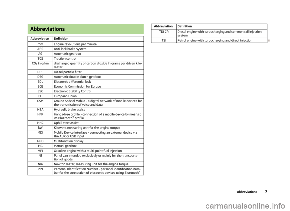
AbbreviationsAbbreviationDefinitionrpmEngine revolutions per minuteABSAnti-lock brake systemAGAutomatic gearboxTCSTraction controlCO2 in g/kmdischarged quantity of carbon dioxide in grams per driven kilo-
meterDPFDiesel particle filterDSGAutomatic double clutch gearboxEDLElectronic differential lockECEEconomic Commission for EuropeESCElectronic Stability ControlEUEuropean UnionGSMGroupe Spécial Mobile - a digital network of mobile devices for the transmission of voice and dataHBAHydraulic brake assistHFPHands-free profile - connection of a mobile device by means of
its Bluetooth ®
profileHHCUphill start assistkWKilowatt, measuring unit for the engine outputMDIMobile Device Interface - connecting an external device via
the AUX or USB inputMFDMultifunction displayMGManual gearboxMPIGasoline engine with a multi-point fuel injectionN1Panel van intended exclusively or mainly for the transporta-
tion of goodsNmNewton meter, measuring unit for the engine torquePINPersonal Identification Number - personal identification num-
ber for the connection of electronic devices using Bluetooth ®AbbreviationDefinitionTDI CRDiesel engine with turbocharging and common rail injection
systemTSIPetrol engine with turbocharging and direct injection
7Abbreviations
Page 12 of 226
Using the system
Cockpit
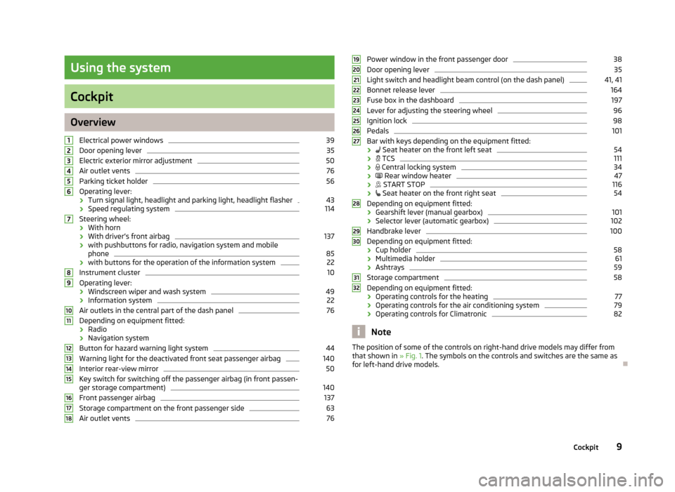
OverviewElectrical power windows
39
Door opening lever
35
Electric exterior mirror adjustment
50
Air outlet vents
76
Parking ticket holder
56
Operating lever:
› Turn signal light, headlight and parking light, headlight flasher
43
›
Speed regulating system
114
Steering wheel:
› With horn
› With driver’s front airbag
137
›with pushbuttons for radio, navigation system and mobile
phone
85
› with buttons for the operation of the information system
22
Instrument cluster
10
Operating lever:
› Windscreen wiper and wash system
49
›
Information system
22
Air outlets in the central part of the dash panel
76
Depending on equipment fitted:
› Radio
› Navigation system
Button for hazard warning light system
44
Warning light for the deactivated front seat passenger airbag
140
Interior rear-view mirror
50
Key switch for switching off the passenger airbag (in front passen-
ger storage compartment)
140
Front passenger airbag
137
Storage compartment on the front passenger side
63
Air outlet vents
76123456789101112131415161718Power window in the front passenger door38Door opening lever35
Light switch and headlight beam control (on the dash panel)
41, 41
Bonnet release lever
164
Fuse box in the dashboard
197
Lever for adjusting the steering wheel
96
Ignition lock
98
Pedals
101
Bar with keys depending on the equipment fitted:
›
Seat heater on the front left seat
54
›
TCS
111
›
Central locking system
34
›
Rear window heater
47
›
START STOP
116
›
Seat heater on the front right seat
54
Depending on equipment fitted:
› Gearshift lever (manual gearbox)
101
›Selector lever (automatic gearbox)
102
Handbrake lever
100
Depending on equipment fitted:
› Cup holder
58
›
Multimedia holder
61
›Ashtrays
59
Storage compartment
58
Depending on equipment fitted:
› Operating controls for the heating
77
›
Operating controls for the air conditioning system
79
›Operating controls for Climatronic
82
Note
The position of some of the controls on right-hand drive models may differ from
that shown in » Fig. 1. The symbols on the controls and switches are the same as
for left-hand drive models.19202122232425262728293031329Cockpit
Page 14 of 226
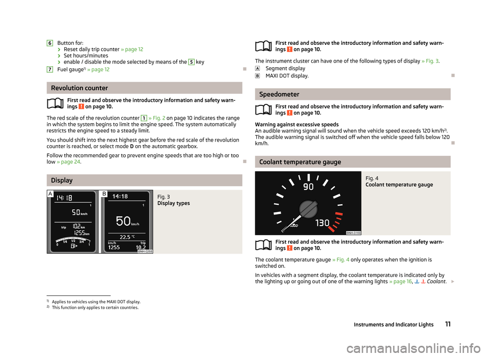
Button for:
› Reset daily trip counter
» page 12
› Set hours/minutes
› enable / disable the mode selected by means of the 5
key
Fuel gauge 1)
» page 12
Revolution counter
First read and observe the introductory information and safety warn-ings
on page 10.
The red scale of the revolution counter
1
» Fig. 2 on page 10 indicates the range
in which the system begins to limit the engine speed. The system automatically
restricts the engine speed to a steady limit.
You should shift into the next highest gear before the red scale of the revolution
counter is reached, or select mode D on the automatic gearbox.
Follow the recommended gear to prevent engine speeds that are too high or too
low » page 24 .
Display
Fig. 3
Display types
67First read and observe the introductory information and safety warn-
ings on page 10.
The instrument cluster can have one of the following types of display » Fig. 3.
Segment display
MAXI DOT display.
Speedometer
First read and observe the introductory information and safety warn-
ings
on page 10.
Warning against excessive speeds
An audible warning signal will sound when the vehicle speed exceeds 120 km/h 2)
.
The audible warning signal is switched off when the vehicle speed falls below 120
km/h.
Coolant temperature gauge
Fig. 4
Coolant temperature gauge
First read and observe the introductory information and safety warn-
ings on page 10.
The coolant temperature gauge » Fig. 4 only operates when the ignition is
switched on.
In vehicles with a segment display, the coolant temperature is indicated only by
the lighting up or going out of one of the warning lights » page 16,
Coolant
.
1)
Applies to vehicles using the MAXI DOT display.
2)
This function only applies to certain countries.
11Instruments and Indicator Lights
Page 16 of 226
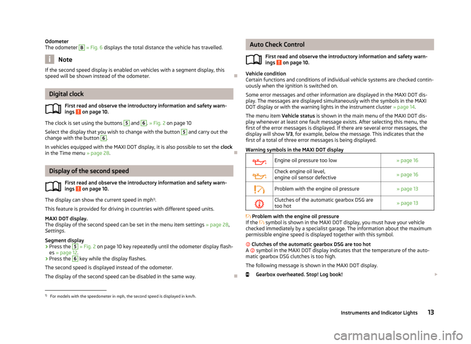
Odometer
The odometer B » Fig. 6 displays the total distance the vehicle has travelled.
Note
If the second speed display is enabled on vehicles with a segment display, this
speed will be shown instead of the odometer.
Digital clock
First read and observe the introductory information and safety warn-ings
on page 10.
The clock is set using the buttons
5
and
6
. » Fig. 2 on page 10
Select the display that you wish to change with the button
5
and carry out the
change with the button
6
.
In vehicles equipped with the MAXI DOT display, it is also possible to set the clock
in the Time menu » page 28.
Display of the second speed
First read and observe the introductory information and safety warn-
ings
on page 10.
The display can show the current speed in mph 1)
.
This feature is provided for driving in countries with different speed units.
MAXI DOT display.
The display of the second speed can be set in the menu item settings » page 28,
Settings .
Segment display
›
Press the
5
» Fig. 2 on page 10 key repeatedly until the odometer display flash-
es » page 12 .
›
Press the
6
key while the display flashes.
The second speed is displayed instead of the odometer. The display of the second speed can be disabled in the same way.
Auto Check Control
First read and observe the introductory information and safety warn-
ings
on page 10.
Vehicle condition
Certain functions and conditions of individual vehicle systems are checked contin-
uously when the ignition is switched on.
Some error messages and other information are displayed in the MAXI DOT dis-play. The messages are displayed simultaneously with the symbols in the MAXI DOT display or with the warning lights in the instrument cluster » page 14.
The menu item Vehicle status is shown in the main menu of the MAXI DOT dis-
play whenever at least one fault message exists. After selecting this menu, the
first of the error messages is displayed. If there are several error messages, the
display will show 1/3, for example, below the message. This indicates that the
first of a total of three error messages is being displayed.
Warning symbols in the MAXI DOT display
Engine oil pressure too low» page 16Check engine oil level,
engine oil sensor defective» page 16Problem with the engine oil pressure» page 13Clutches of the automatic gearbox DSG are too hot» page 13
Problem with the engine oil pressure
If the
symbol is shown in the MAXI DOT display, you must have your vehicle
checked immediately by a specialist garage. The information about the maximum
permissible engine speed is displayed together with this symbol.
Clutches of the automatic gearbox DSG are too hot
A
symbol in the MAXI DOT display indicates that the temperature of the auto-
matic gearbox DSG clutches is too high.
The following message is shown in the MAXI DOT display. Gearbox overheated. Stop! Log book!
1)
For models with the speedometer in mph, the second speed is displayed in km/h.
13Instruments and Indicator Lights
Page 17 of 226
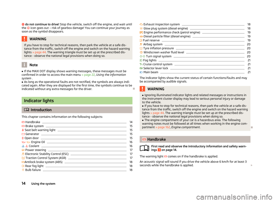
do not continue to drive! Stop the vehicle, switch off the engine, and wait until
the icon goes out – risk of gearbox damage! You can continue your journey as
soon as the symbol disappears.WARNINGIf you have to stop for technical reasons, then park the vehicle at a safe dis- tance from the traffic, switch off the engine and switch on the hazard warning
lights » page 44 . The warning triangle must be set up at the prescribed dis-
tance - observe the national legal provisions when doing so.
Note
■ If the MAXI DOT display shows warning messages, these messages must be
confirmed in order to access the main menu » page 22, Using the information
system .■
As long as the operational faults are not rectified, the symbols are always indi-
cated again. After they are displayed for the first time, the symbols continue to be
indicated without any extra messages for the driver.
Indicator lights
Introduction
This chapter contains information on the following subjects:
Handbrake
14
Brake system
15
Seat belt warning light
15
Generator
15
Open door
15
Engine Oil
16
Coolant
16
Power steering
17
Electronic Stability Control (ESC)
17
Traction Control System (ASR)
17
Antilock brake system (ABS)
18
Rear fog light
18
Bulb failure
18 Exhaust inspection system18 Glow plug system (diesel engine)18
Engine performance check (petrol engine)
19
Diesel particle filter (diesel engine)
19
Fuel reserve
19
Airbag system
20
Tyre inflation pressure
20
Windscreen washer fluid level
20
Turn signal system
20
Fog lights
21
Cruise control system
21
Selector lever lock
21
Main beam
21
The indicator lights show the current status of certain functions/faults and may
be accompanied by audible signals.
WARNING■ Ignoring illuminated indicator lights and related messages or instructions in
the instrument cluster display may lead to serious personal injury or damage
to the vehicle.■
If you have to stop for technical reasons, then park the vehicle at a safe dis-
tance from the traffic, switch off the engine and switch on the hazard warning
lights » page 44 . The warning triangle must be set up at the prescribed dis-
tance - observe the national legal provisions when doing so.
■
The engine compartment of your car is a hazardous area. The following
warning notes must be followed at all times when working in the engine com-
partment » page 162 , Engine compartment .
Handbrake
First read and observe the introductory information and safety warn-
ings
on page 14.
The warning light
comes on if the handbrake is applied.
An acoustic signal will sound if you drive the vehicle above 6 km/h for at least 3
seconds while the handbrake is applied.
14Using the system
Page 25 of 226
Information system
Driver information system
Introduction
This chapter contains information on the following subjects:
Using the information system
22
Ice warning
23
Gear recommendation
24
Door, boot or engine compartment warning
24
Compass point display
24
The information system provides the driver with alerts and messages about in-
dividual vehicle systems. This information and advice is shown in the instrument
cluster display or indicated by the illumination of the corresponding indicator light in the instrument cluster.
Depending on the vehicle equipment, the information system provides the fol-
lowing advice and information.
› Ice warning
» page 23.
› Recommended gear
» page 24.
› Door, boot lid or bonnet warning
» page 24.
› Compass display
» page 24.
› Data relating to the multi-function display (MFD)
» page 25.
› Warning against excessive speed
» page 27.
› Data relating to the Maxi DOT display
» page 27.
› Service interval display
» page 28.
› Auto Check Control
» page 13.
› Selector lever positions for an automatic gearbox
» page 102.WARNINGConcentrate fully on your driving at all times! As the driver, you are fully re-
sponsible for the operation of your vehicle.
Using the information system
Fig. 7
Buttons/adjustment wheel: on the operating lever/on the multifunc-
tion steering wheel
First read and observe the introductory information and safety warn-
ings on page 22.
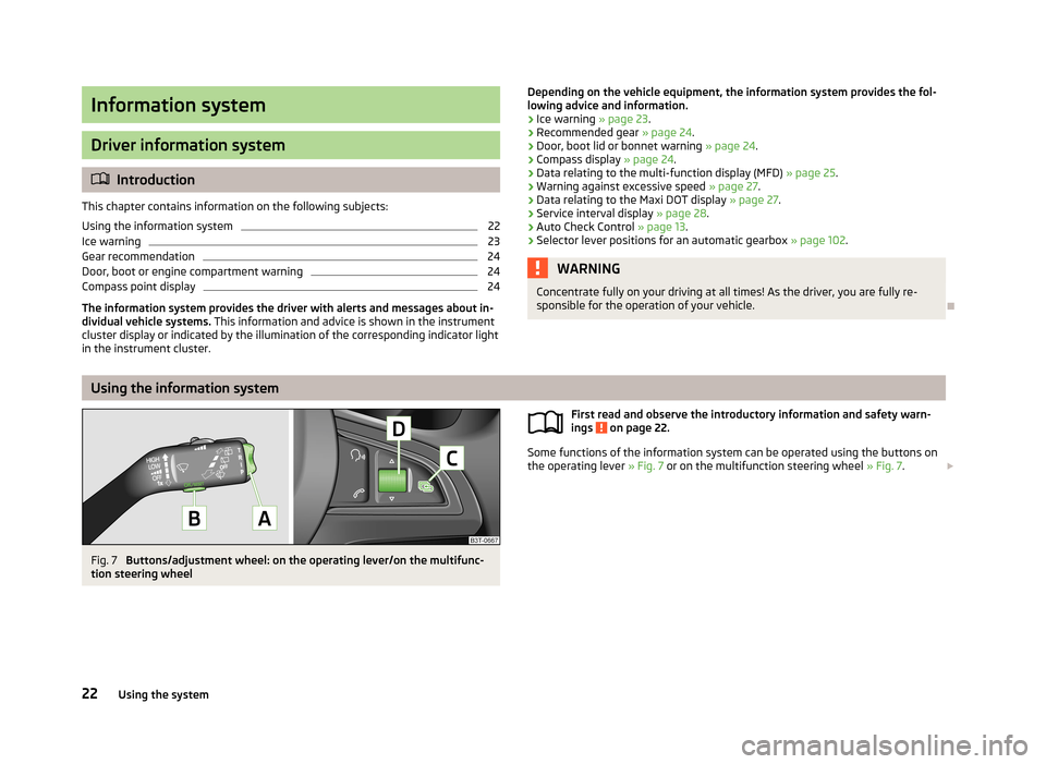
Some functions of the information system can be operated using the buttons on
the operating lever » Fig. 7 or on the multifunction steering wheel » Fig. 7.
22Using the system
Page 30 of 226
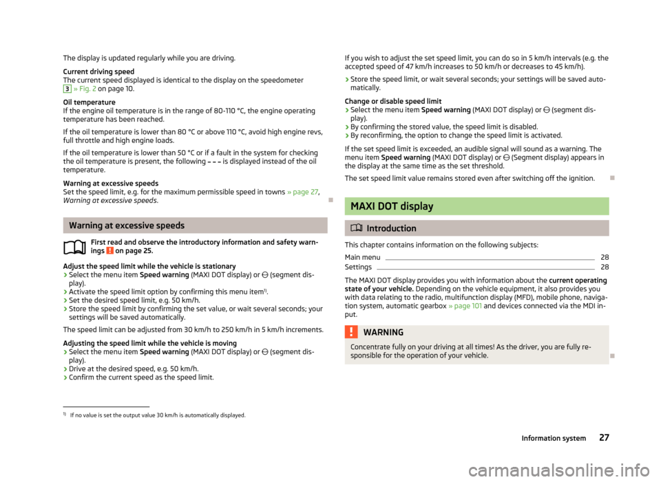
The display is updated regularly while you are driving.Current driving speed
The current speed displayed is identical to the display on the speedometer3
» Fig. 2 on page 10.
Oil temperature
If the engine oil temperature is in the range of 80-110 °C, the engine operating
temperature has been reached.
If the oil temperature is lower than 80 °C or above 110 °C, avoid high engine revs, full throttle and high engine loads.
If the oil temperature is lower than 50 °C or if a fault in the system for checking
the oil temperature is present, the following
is displayed instead of the oil
temperature.
Warning at excessive speeds
Set the speed limit, e.g. for the maximum permissible speed in towns » page 27,
Warning at excessive speeds .
Warning at excessive speeds
First read and observe the introductory information and safety warn-
ings
on page 25.
Adjust the speed limit while the vehicle is stationary
›
Select the menu item Speed warning (MAXI DOT display) or
(segment dis-
play).
›
Activate the speed limit option by confirming this menu item 1)
.
›
Set the desired speed limit, e.g. 50 km/h.
›
Store the speed limit by confirming the set value, or wait several seconds; your
settings will be saved automatically.
The speed limit can be adjusted from 30 km/h to 250 km/h in 5 km/h increments.
Adjusting the speed limit while the vehicle is moving
›
Select the menu item Speed warning (MAXI DOT display) or
(segment dis-
play).
›
Drive at the desired speed, e.g. 50 km/h.
›
Confirm the current speed as the speed limit.
If you wish to adjust the set speed limit, you can do so in 5 km/h intervals (e.g. the
accepted speed of 47 km/h increases to 50 km/h or decreases to 45 km/h).›
Store the speed limit, or wait several seconds; your settings will be saved auto-
matically.
Change or disable speed limit
›
Select the menu item Speed warning (MAXI DOT display) or (segment dis-
play).
›
By confirming the stored value, the speed limit is disabled.
›
By reconfirming, the option to change the speed limit is activated.
If the set speed limit is exceeded, an audible signal will sound as a warning. The menu item Speed warning (MAXI DOT display) or (Segment display) appears in
the display at the same time as the set threshold.
The set speed limit value remains stored even after switching off the ignition.
MAXI DOT display
Introduction
This chapter contains information on the following subjects:
Main menu
28
Settings
28
The MAXI DOT display provides you with information about the current operating
state of your vehicle. Depending on the vehicle equipment, it also provides you
with data relating to the radio, multifunction display (MFD), mobile phone, naviga-
tion system, automatic gearbox » page 101 and devices connected via the MDI in-
put.
WARNINGConcentrate fully on your driving at all times! As the driver, you are fully re-
sponsible for the operation of your vehicle.
1)
If no value is set the output value 30 km/h is automatically displayed.
27Information system
Page 102 of 226
›Depress and hold the clutch pedal (vehicles with a manual gearbox) or brake
pedal (vehicles with an automatic gearbox) until the engine starts.›
Turn the key into position
3
to the stop and release immediately after the en-
gine has been started – do not apply the accelerator.
After letting go, the vehicle key will return to position
2
.
›
Release the handbrake.
If the engine does not start within 10 seconds, turn the key to position
1
. Repeat
the start-up process after approx. half a minute.
Vehicles with manual transmission
The engine will not start if the clutch pedal is not depressed.
The following message is shown in the information cluster display.
Depress clutch to start.
CLUTCH
Vehicles with automatic transmission
The engine will not start if the brake pedal is not depressed.
The warning light
lights up in the instrument cluster and the following mes-
sage appears in the display.
Apply the brake to start.
BRAKE
CAUTION
If the engine does not start up after a second attempt, the fuse for the fuel pump may have a fault. Check the fuse and replace if necessary » page 197, Fuses in
the dash panel , or seek assistance from a specialist garage.
Switching off the engine
First read and observe the introductory information and safety warn-ings
on page 97.
Switch off the engine by turning the ignition key into position
1
» Fig. 90 on
page 98.
For vehicles with automatic transmission, the ignition key can only be removed if
the selector lever is in position P.
Brakes
Introduction
This chapter contains information on the following subjects:
Information on braking
100
Handbrake
100WARNING■ Greater physical effort is required for braking when the engine is switched
off – risk of accident!■
The clutch pedal must be actuated when braking on a vehicle with manual
transmission, when the vehicle is in gear and at low revs. Otherwise, the func-
tion of the brake booster may be impaired – risk of accident!
■
Never leave children unattended in the vehicle. The children might, for ex-
ample, release the handbrake or take the vehicle out of gear. The vehicle
could then start to move – risk of accident!
WARNING■ In the event of damage occurring to the standard fitted front spoiler or the
retrofitting of another front spoiler, wheel hubs etc. » page 149, Service work,
adjustments and technical alterations , It must be ensured that the air supply
to the front brakes is not impaired. The front brakes may overheat, which can
have a negative impact on the functioning of the braking system – risk of acci-
dent!
CAUTION
■ Observe the recommendations on the new brake pads » page 105.■Never let the brakes slip with light pressure on the pedal if braking is not neces-
sary. This causes the brakes to overheat and can also result in a longer braking distance and excessive wear.
99Starting-off and Driving
Page 104 of 226
WARNINGPlease note that the handbrake must be fully released. A handbrake which is
only partially released can result in the rear brakes overheating. This can have a negative effect on the operation of the brake system – risk of accident!
Manual gear changing and pedals
Introduction
This chapter contains information on the following subjects:
Manual gear changing
101
Pedals
101
Manual gear changing
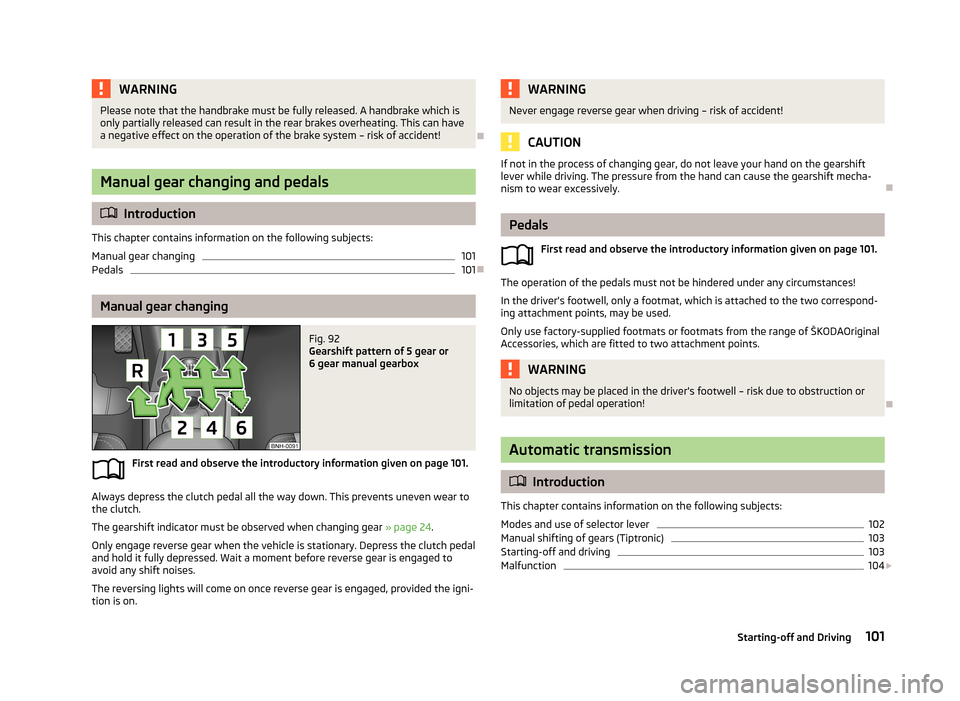
Fig. 92
Gearshift pattern of 5 gear or
6 gear manual gearbox
First read and observe the introductory information given on page 101.
Always depress the clutch pedal all the way down. This prevents uneven wear to
the clutch.
The gearshift indicator must be observed when changing gear » page 24.
Only engage reverse gear when the vehicle is stationary. Depress the clutch pedal
and hold it fully depressed. Wait a moment before reverse gear is engaged to
avoid any shift noises.
The reversing lights will come on once reverse gear is engaged, provided the igni- tion is on.
WARNINGNever engage reverse gear when driving – risk of accident!
CAUTION
If not in the process of changing gear, do not leave your hand on the gearshift
lever while driving. The pressure from the hand can cause the gearshift mecha-nism to wear excessively.
Pedals
First read and observe the introductory information given on page 101.
The operation of the pedals must not be hindered under any circumstances!
In the driver's footwell, only a footmat, which is attached to the two correspond- ing attachment points, may be used.
Only use factory-supplied footmats or footmats from the range of ŠKODAOriginal Accessories, which are fitted to two attachment points.
WARNINGNo objects may be placed in the driver's footwell – risk due to obstruction or
limitation of pedal operation!
Automatic transmission
Introduction
This chapter contains information on the following subjects:
Modes and use of selector lever
102
Manual shifting of gears (Tiptronic)
103
Starting-off and driving
103
Malfunction
104
101Starting-off and Driving