ECU SKODA ROOMSTER 2010 1.G Owner's Guide
[x] Cancel search | Manufacturer: SKODA, Model Year: 2010, Model line: ROOMSTER, Model: SKODA ROOMSTER 2010 1.GPages: 231, PDF Size: 12.91 MB
Page 184 of 231
Breakdown assistance183
Using the system
Safety
Driving Tips
General Maintenance
Breakdown assistance
Praktik
Technical Data
Changing a wheelPreliminary workThe following steps should be carried ou t before actually changing the wheel.
– If it is necessary to change a wheel, park the vehicle as far away as possible from
the traffic flow. The place you choose should be level.
– Have all the occupants get out. While changing a wheel, the occupants of the
vehicle should not stand on the road (e.g. behind a crash barrier).
– Apply the handbrake firmly.
–Engage 1st gear or if your vehicle is fitted with an automatic gearbox, position the
selector lever into position P .
– If a trailer is coupled, uncouple it.
– Take the vehicle tool kit and the spare wheel page 181 out of the luggage
compartment.
WARNING
If you find yourself in flowing traffic switch on the hazard warning lights
system and place the warning triangle on the side of the road at the prescribed
distance from your vehicle while observing all national legal provisions. In this
way you are protecting not only yourself but also other road users.
Never start the engine with the vehicle si tting on the raised jack - danger of
suffering injury.Caution
If you have to change a wheel on a slope first block the opposite wheel with a stone or
similar object in order to secure the vehicle from unexpectedly rolling away.
Note
Comply with the national legal regulations.
Always change a wheel on a level surface as far as possible.
– Take off the full wheel trim* page 184 or the caps page 184.
– Slacken the wheel bolts page 185.
– Jack up the vehicle until the wheel to be changed is clear of the ground
page 185.
– Unscrew the wheel bolts and place them on a clean surface (cloth, paper etc.).
– Take off the wheel.
– Fit on the spare wheel* and tighten the wheel bolts slightly.
– Lower the car.
– Tighten the wheel bolts firmly, alternatel y and diagonally using the wrench (cross-
wise) page 185.
– Mount the full wheel trim/wheel trim cap or the caps.
Note
All bolts must be clean and must turn easily.
You must never grease or oil the wheel bolts!
When fitting on unidirectiona l tyres, ensure that the tyres rotate in the correct
direction page 173.
Subsequent stepsAfter changing the wheel, you mu st perform the following steps.
– Stow the vehicle tool kit in the space provided.
– Stow the replaced wheel in the luggage compartment.
– Check the tyre pressure on the spare wheel just mounted as soon as possible.
– Have the tightening torque of the wheel bolts checked with a torque wrench as
soon as possible. Steel and light alloy wheels must be tightened to a tightening
torque of 120 Nm.
s16g.4.book Page 183 Wednesda y, February 10, 2010 3:53 PM
Page 185 of 231
Breakdown assistance
184
– Change the damaged wheel or consult a specialist garage about possibilities for
getting repairs done.
WARNING
It is necessary to observe the guidelines given on page 175, “New tyres and
wheels” if the vehicle is subsequently fitted with tyres which are different to
those it was fitted with at the works.
Note
If you find, when changing the wheel, that the wheel bolts are corroded and diffi-
cult to turn, the bolts must be replaced before checking the tightening torque.
Drive cautiously and only at a moderate speed to a workshop where the tightening
torque can be checked.
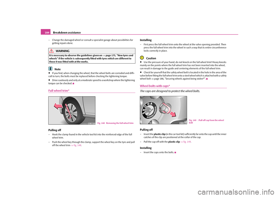
Full wheel trim*Pulling off– Hook the clamp found in the vehicle tool kit into the reinforced edge of the full
wheel trim.
– Push the wheel key through the clamp, support the wheel key on the tyre and pull off the wheel trim fig. 148 .
Installing– First press the full wheel trim onto the wheel at the valve opening provided. Then
press the full wheel trim into the wheel in such a way that its entire circumference
locks correctly in place.
Caution
Use the pressure of your hand, do not knock on the full wheel trim! Heavy knocks
mainly on the points where the full wheel trim has not been inserted into the wheel,
can result in damage to the guide and centering elements of the full wheel trim.
Check for yourself that the safety wheel bolt is located in the hole in the area of the
valve before fitting the full wheel trim onto a steel wheel which is attached with a safety
wheel bolt page 186, “Securing wheels against being stolen*”.
Wheel bolts with caps*
The caps are designed to protect the wheel bolts.Pulling off– Insert the plastic clip (in the car tool kit) sufficiently far onto the cap until the inner
catches of the clip are positioned at the collar of the cap.
– Pull the cap off with the plastic clip fig. 149.Installing– Insert the caps onto the bolts.
Fig. 148 Removing the full wheel trim
Fig. 149 : Pull off cap from the wheel
bolt
s16g.4.book Page 184 Wednesda y, February 10, 2010 3:53 PM
Page 187 of 231
Breakdown assistance
186
Not positioning the lifting jack at the specified points can result in damage
to the vehicle. The jack can also slip off if it does not have sufficient grip - risk of
injury!
Never start the engine if the vehicle is lifted - risk of accident.
Never lie under the vehicle if the vehicle is only lifted with the vehicle lifting
jack.
It is important to support the vehicle with suitable supporting blocks if you
wish to work under the lifted vehicle - risk of injury!
Securing wheels against being stolen*
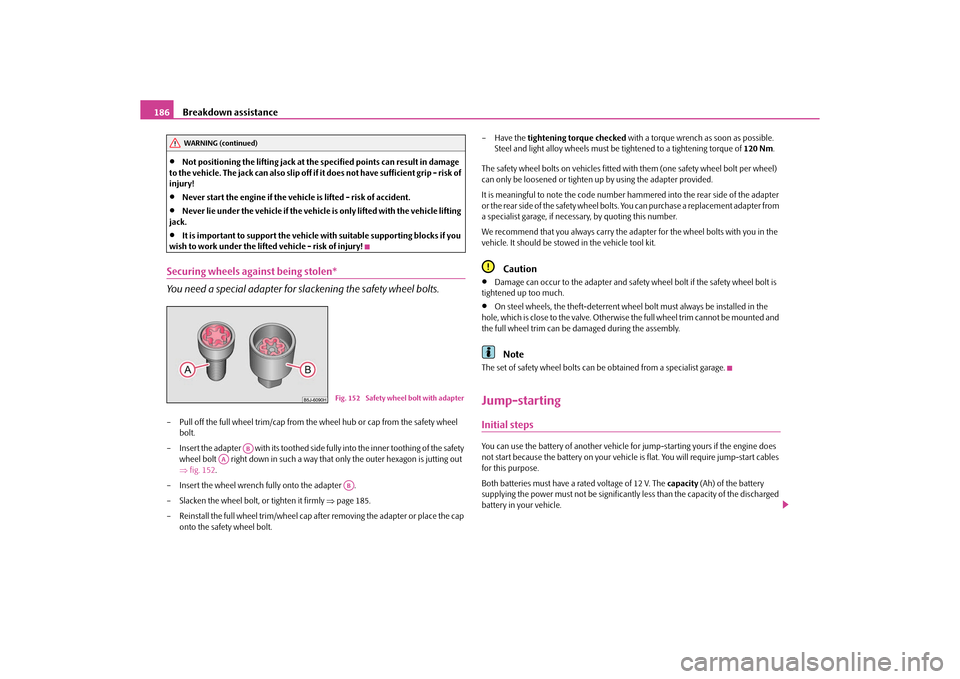
You need a special adapter for sl ackening the safety wheel bolts.– Pull off the full wheel trim/cap from the wheel hub or cap from the safety wheel
bolt.
– Insert the adapter with its toothed side fully into the inner toothing of the safety wheel bolt right down in such a way th at only the outer hexagon is jutting out
fig. 152 .
– Insert the wheel wrench fully onto the adapter .
– Slacken the wheel bolt, or tighten it firmly page 185.
– Reinstall the full wheel trim/wheel cap afte r removing the adapter or place the cap
onto the safety wheel bolt. – Have the
tightening torque checked with a torque wrench as soon as possible.
Steel and light alloy wheels must be tightened to a tightening torque of 120 Nm.
The safety wheel bolts on vehicles fitted with them (one safety wheel bolt per wheel)
can only be loosened or tighten up by using the adapter provided.
It is meaningful to note th e code number hammered into the rear side of the adapter
or the rear side of the safety wheel bolts. You can purchase a replacement adapter from
a specialist garage, if necessary, by quoting this number.
We recommend that you always carry the ad apter for the wheel bolts with you in the
vehicle. It should be stow ed in the vehicle tool kit.
Caution
Damage can occur to the adapter and safety wheel bolt if the safety wheel bolt is
tightened up too much.
On steel wheels, the theft-deterrent wheel bolt must always be installed in the
hole, which is close to the valve. Otherwise the full wheel trim cannot be mounted and
the full wheel trim can be damaged during the assembly.Note
The set of safety wheel bolts can be obtained from a specialist garage.Jump-startingInitial stepsYou can use the battery of another vehicle fo r jump-starting yours if the engine does
not start because the battery on your vehicle is flat. You will require jump-start cables
for this purpose.
Both batteries must have a rated voltage of 12 V. The capacity (Ah) of the battery
supplying the power must not be significantly less than the capacity of the discharged
battery in your vehicle.
WARNING (continued)
Fig. 152 Safety wheel bolt with adapter
AB
AA
AB
s16g.4.book Page 186 Wednesda y, February 10, 2010 3:53 PM
Page 198 of 231
Fuses and light bulbs197
Using the system
Safety
Driving Tips
General Maintenance
Breakdown assistance
Praktik
Technical Data
WARNING
Bulbs H7 and H4 are pressurised and may burst when changing the bulb -
risk of injury!
It is recommended to wear gloves and safety glasses when changing a bulb.Note
This Owner's Manual only describes the replacement of bulbs where it is assumed that
no major complications will arise. Other light bulbs should be replaced by your
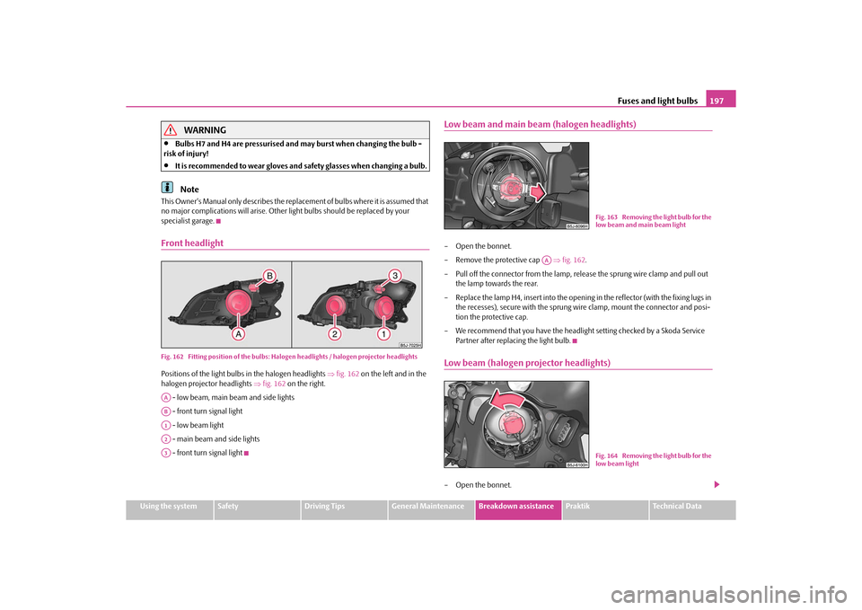
specialist garage.Front headlightFig. 162 Fitting position of the bulbs: Halo gen headlights / halogen projector headlightsPositions of the light bulbs in the halogen headlights fig. 162 on the left and in the
halogen projector headlights fig. 162 on the right.
- low beam, main beam and side lights
- front turn signal light
- low beam light
- main beam and side lights
- front turn signal light
Low beam and main beam (halogen headlights)– Open the bonnet.
– Remove the protective cap fig. 162 .
– Pull off the connector from the lamp, rele ase the sprung wire clamp and pull out
the lamp towards the rear.
– Replace the lamp H4, insert into the opening in the reflector (with the fixing lugs in the recesses), secure with the sprung wi re clamp, mount the connector and posi-
tion the protective cap.
– We recommend that you have the headli ght setting checked by a Skoda Service
Partner after replacing the light bulb.Low beam (halogen projector headlights)– Open the bonnet.
AAABA1A2A3
Fig. 163 Removing the light bulb for the
low beam and main beam light
AA
Fig. 164 Removing the light bulb for the
low beam light
s16g.4.book Page 197 Wednesda y, February 10, 2010 3:53 PM
Page 199 of 231
Fuses and light bulbs
198
– Remove the protective cap page 197, fig. 162 on the right.
– Turn the connector with the light bulb up to the stop towards the left and remove.
– Replace the halogen lamp H7, insert the connector with the new halogen lamp and turn to the right up to the stop.
– Insert the protective cap.
– We recommend that you have the headlight setting checked by a Skoda Service Partner after replacing the light bulb.Main beam (halogen projector headlights)– Open the bonnet.
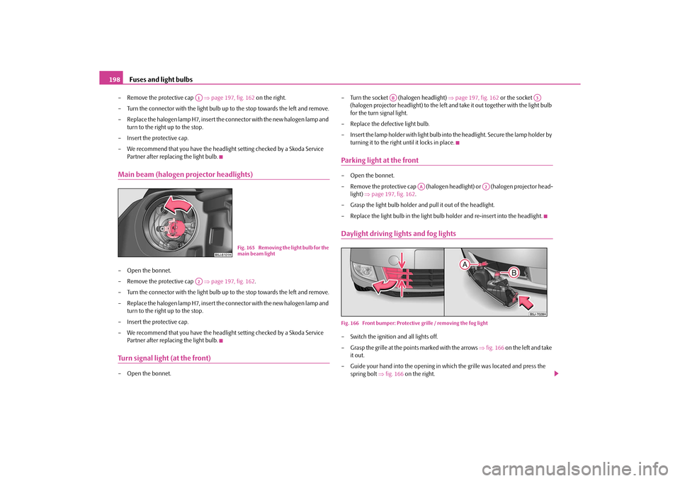
– Remove the protective cap page 197, fig. 162 .
– Turn the connector with the light bulb up to the stop towards the left and remove.
– Replace the halogen lamp H7, insert the connector with the new halogen lamp and turn to the right up to the stop.
– Insert the protective cap.
– We recommend that you have the headlight setting checked by a Skoda Service Partner after replacing the light bulb.Turn signal light (at the front)– Open the bonnet. – Turn the socket (halogen headlight)
page 197, fig. 162 or the socket
(halogen projector headlight) to the left and take it out together with the light bulb
for the turn signal light.
– Replace the defective light bulb.
– Insert the lamp holder with light bulb into the headlight. Secure the lamp holder by
turning it to the right until it locks in place.
Parking light at the front– Open the bonnet.
– Remove the protective cap (halogen headlight) or (halogen projector head- light) page 197, fig. 162 .
– Grasp the light bulb holder and pull it out of the headlight.
– Replace the light bulb in the light bulb holder and re-insert into the headlight.Daylight driving lights and fog lightsFig. 166 Front bumper: Protective grille / removing the fog light– Switch the ignition and all lights off.
– Grasp the grille at the points marked with the arrows fig. 166 on the left and take
it out.
– Guide your hand into the opening in wh ich the grille was located and press the
spring bolt fig. 166 on the right.
A1
Fig. 165 Removing the light bulb for the
main beam light
A2
AB
A3
AA
A2
s16g.4.book Page 198 Wednesda y, February 10, 2010 3:53 PM
Page 226 of 231
Index225
Using the system
Safety
Driving Tips
General Maintenance
Breakdown assistance
Praktik
Technical Data
Remote control . . . . . . . . . . . . . . . . . . . . . . . . . . . . . . . 40
Synchronisation process . . . . . . . . . . . . . . . . . . . 41
Removing seats . . . . . . . . . . . . . . . . . . . . . . . . . . . . . . . 60
Replacing bulbs . . . . . . . . . . . . . . . . . . . . . . . . . . . . . . 196
Replacing fuses . . . . . . . . . . . . . . . . . . . . . . . . . . . . . . 191
Replacing the wiper blades . . . . . . . . . . . . . . . . . . . . 54
Roof aerial . . . . . . . . . . . . . . . . . . . . . . . . . . . . . . . . . . 151
Running in the car . . . . . . . . . . . . . . . . . . . . . . . . . . . 141
SSafe securing . . . . . . . . . . . . . . . . . . . . . . . . . . . . . . . . . 36
Safety . . . . . . . . . . . . . . . . . . . . . . . . . . . . . . . . . . . . . . . 109
Safety information Engine compartment . . . . . . . . . . . . . . . . . . . . . 162
Saving electrical energy . . . . . . . . . . . . . . . . . . . . . . 142
Seat belt height adjuster . . . . . . . . . . . . . . . . . . . . . . 115
Seat belt warning light . . . . . . . . . . . . . . . . . . . . . . . . 115
Seat belts . . . . . . . . . . . . . . . . . . . . . . . . . . . . . . . . . . . . 113 Cleaning . . . . . . . . . . . . . . . . . . . . . . . . . . . . . . . . . 157
fastening . . . . . . . . . . . . . . . . . . . . . . . . . . . . . . . . 115
Height adjustment . . . . . . . . . . . . . . . . . . . . . . . . 115
Safety information . . . . . . . . . . . . . . . . . . . . . . . . 114
taking off . . . . . . . . . . . . . . . . . . . . . . . . . . . . . . . . 116
Warning light . . . . . . . . . . . . . . . . . . . . . . . . . . . . . 33
Seats . . . . . . . . . . . . . . . . . . . . . . . . . . . . . . . . . . . . . . . . . 57 Heating . . . . . . . . . . . . . . . . . . . . . . . . . . . . . . . . . . . 59
Selector lever . . . . . . . . . . . . . . . . . . . . . . . . . . . . . . . . . 95
Selector lever positions . . . . . . . . . . . . . . . . . . . . . . . . 95
Selector lever-emergency unlocking . . . . . . . . . . . . 98
Service Display . . . . . . . . . . . . . . . . . . . . . . . . . . . . . . . 17
Service Interval Display . . . . . . . . . . . . . . . . . . . . . . . . 17 Setting temperature
Air conditioning system . . . . . . . . . . . . . . . . . . . . 82
Heating . . . . . . . . . . . . . . . . . . . . . . . . . . . . . . . . . . . 79
Setting the clock . . . . . . . . . . . . . . . . . . . . . . . . . . . . . . 18
Shifting . . . . . . . . . . . . . . . . . . . . . . . . . . . . . . . . . . . . . . . 90
Side airbag . . . . . . . . . . . . . . . . . . . . . . . . . . . . . . . . . . 121
Side lights . . . . . . . . . . . . . . . . . . . . . . . . . . . . . . . . . . . . 46
Snow chains . . . . . . . . . . . . . . . . . . . . . . . . . . . . . . . . . 177
Spare wheel . . . . . . . . . . . . . . . . . . . . . . . . . . . . . . . . . 182
Speedometer . . . . . . . . . . . . . . . . . . . . . . . . . . . . . . . . . 16
Stability programme (ESP) . . . . . . . . . . . . . . . . . . . . 133
Starting the engine . . . . . . . . . . . . . . . . . . . . . . . . . . . . 88 Diesel engines . . . . . . . . . . . . . . . . . . . . . . . . . . . . . 89
Petrol engines . . . . . . . . . . . . . . . . . . . . . . . . . . . . . 89
Static separation net . . . . . . . . . . . . . . . . . . . . . . . . . . . 65
Steering force assistance . . . . . . . . . . . . . . . . . . . . . . 137
Storage compartment Lighting . . . . . . . . . . . . . . . . . . . . . . . . . . . . . . . . . . . 51
Storage compartments . . . . . . . . . . . . . . . . . . . . . . . . 73
Storage facilities . . . . . . . . . . . . . . . . . . . . . . . . . . . . . . 73
Sun visors . . . . . . . . . . . . . . . . . . . . . . . . . . . . . . . . . . . . 52
Switching lights on and off . . . . . . . . . . . . . . . . . . . . . 46
Switching off the engine . . . . . . . . . . . . . . . . . . . . . . . 89
TTaking care of your vehicle . . . . . . . . . . . . . . . . . . . . 151
TCS . . . . . . . . . . . . . . . . . . . . . . . . . . . . . . . . . . . . . . . . . 134 Warning light . . . . . . . . . . . . . . . . . . . . . . . . . . . . . . 30
Telephone . . . . . . . . . . . . . . . . . . . . . . . . . . . . . . . . . . . 101
Temperature outside . . . . . . . . . . . . . . . . . . . . . . . . . . . . . . . . . . . 20 the first 1 500 kilometres . . . . . . . . . . . . . . . . . . . . . 141
The roof luggage rack system . . . . . . . . . . . . . . . . . . . 70
Tiptronic . . . . . . . . . . . . . . . . . . . . . . . . . . . . . . . . . . . . . 94
Tool . . . . . . . . . . . . . . . . . . . . . . . . . . . . . . . . . . . . . . . . 181
Tourist light . . . . . . . . . . . . . . . . . . . . . . . . . . . . . . . . . . . 47
Towing a trailer . . . . . . . . . . . . . . . . . . . . . . . . . . . . . 148
Towing eye
front . . . . . . . . . . . . . . . . . . . . . . . . . . . . . . . . . . . . 189
rear . . . . . . . . . . . . . . . . . . . . . . . . . . . . . . . . . . . . . 189
Towing protection monitoring . . . . . . . . . . . . . . . . . . 42
towing vehicle . . . . . . . . . . . . . . . . . . . . . . . . . . . . . . 188
Tow-starting . . . . . . . . . . . . . . . . . . . . . . . . . . . . . . . . 188
Tow-starting and towing vehicle Automatic gearbox . . . . . . . . . . . . . . . . . . . . . . . . . 99
Traction control system (TCS) . . . . . . . . . . . . . . . . 134 Warning light . . . . . . . . . . . . . . . . . . . . . . . . . . . . . . 30
Trailer . . . . . . . . . . . . . . . . . . . . . . . . . . . . . . . . . . . . . . 148 General Maintenance . . . . . . . . . . . . . . . . . . . . 148
Transporting children . . . . . . . . . . . . . . . . . . . . . . . . 126
Tread depth . . . . . . . . . . . . . . . . . . . . . . . . . . . . . . . . 174
Turn signal light . . . . . . . . . . . . . . . . . . . . . . . . . . . . . 198
Turn signal lights . . . . . . . . . . . . . . . . . . . . . . . . . . . . . . 50 Warning light . . . . . . . . . . . . . . . . . . . . . . . . . . . . . . 26
Two-way radio systems . . . . . . . . . . . . . . . . . . . . . . 101
Tyre . . . . . . . . . . . . . . . . . . . . . . . . . . . . . . . . . . . . . . . . 173
Tyre inflation pressure Warning light . . . . . . . . . . . . . . . . . . . . . . . . . . . . . . 30
Tyre pressure monitoring system . . . . . . . . . . . . . 138
Tyre repair kit . . . . . . . . . . . . . . . . . . . . . . . . . . . . . . . 182
Tyres Winter tyres . . . . . . . . . . . . . . . . . . . . . . . . . . . . . 177
s16g.4.book Page 225 Wednesda y, February 10, 2010 3:53 PM