engine coolant SKODA ROOMSTER 2011 1.G Owner's Manual
[x] Cancel search | Manufacturer: SKODA, Model Year: 2011, Model line: ROOMSTER, Model: SKODA ROOMSTER 2011 1.GPages: 212, PDF Size: 3.3 MB
Page 5 of 212
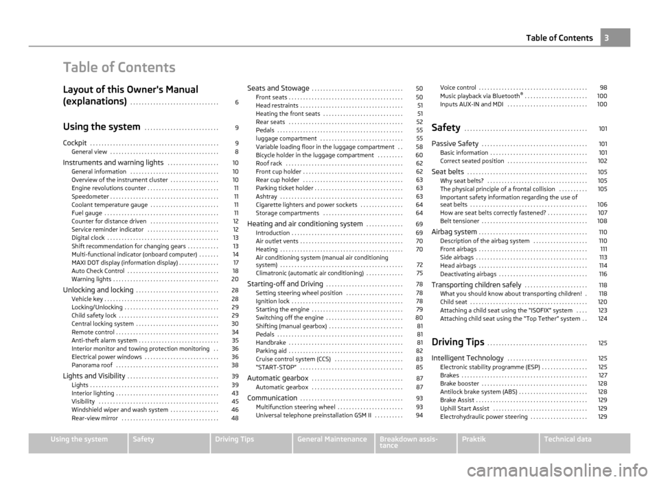
Table of Contents
Layout of this Owner's Manual
(explanations)
. . . . . . . . . . . . . . . . . . . . . . . . . . . . . . . 6
Using the system . . . . . . . . . . . . . . . . . . . . . . . . . . 9
Cockpit . . . . . . . . . . . . . . . . . . . . . . . . . . . . . . . . . . . . . . . . . . . . . 9
General view . . . . . . . . . . . . . . . . . . . . . . . . . . . . . . . . . . . . . . 8
Instruments and warning lights . . . . . . . . . . . . . . . . . . 10
General information . . . . . . . . . . . . . . . . . . . . . . . . . . . . . . . 10
Overview of the instrument cluster . . . . . . . . . . . . . . . . . 10
Engine revolutions counter . . . . . . . . . . . . . . . . . . . . . . . . . 11
Speedometer . . . . . . . . . . . . . . . . . . . . . . . . . . . . . . . . . . . . . . 11
Coolant temperature gauge . . . . . . . . . . . . . . . . . . . . . . . . 11
Fuel gauge . . . . . . . . . . . . . . . . . . . . . . . . . . . . . . . . . . . . . . . . 11
Counter for distance driven . . . . . . . . . . . . . . . . . . . . . . . . 12
Service reminder indicator . . . . . . . . . . . . . . . . . . . . . . . . . 12
Digital clock . . . . . . . . . . . . . . . . . . . . . . . . . . . . . . . . . . . . . . . 13
Shift recommendation for changing gears . . . . . . . . . . . 13
Multi-functional indicator (onboard computer) . . . . . . . 14
MAXI DOT display (information display) . . . . . . . . . . . . . . 17
Auto Check Control . . . . . . . . . . . . . . . . . . . . . . . . . . . . . . . . 18
Warning lights . . . . . . . . . . . . . . . . . . . . . . . . . . . . . . . . . . . . . 20
Unlocking and locking . . . . . . . . . . . . . . . . . . . . . . . . . . . . . 28
Vehicle key . . . . . . . . . . . . . . . . . . . . . . . . . . . . . . . . . . . . . . . . 28
Locking/Unlocking . . . . . . . . . . . . . . . . . . . . . . . . . . . . . . . . . 29
Child safety lock . . . . . . . . . . . . . . . . . . . . . . . . . . . . . . . . . . . 29
Central locking system . . . . . . . . . . . . . . . . . . . . . . . . . . . . . 30
Remote control . . . . . . . . . . . . . . . . . . . . . . . . . . . . . . . . . . . . 34
Anti-theft alarm system . . . . . . . . . . . . . . . . . . . . . . . . . . . . 35
Interior monitor and towing protection monitoring . . 36
Electrical power windows . . . . . . . . . . . . . . . . . . . . . . . . . . 36
Panorama roof . . . . . . . . . . . . . . . . . . . . . . . . . . . . . . . . . . . . 38
Lights and Visibility . . . . . . . . . . . . . . . . . . . . . . . . . . . . . . . . 39
Lights . . . . . . . . . . . . . . . . . . . . . . . . . . . . . . . . . . . . . . . . . . . . . 39
Interior lighting . . . . . . . . . . . . . . . . . . . . . . . . . . . . . . . . . . . . 43
Visibility . . . . . . . . . . . . . . . . . . . . . . . . . . . . . . . . . . . . . . . . . . 45
Windshield wiper and wash system . . . . . . . . . . . . . . . . . 46
Rear-view mirror . . . . . . . . . . . . . . . . . . . . . . . . . . . . . . . . . . 48 Seats and Stowage
. . . . . . . . . . . . . . . . . . . . . . . . . . . . . . . . 50
Front seats . . . . . . . . . . . . . . . . . . . . . . . . . . . . . . . . . . . . . . . . 50
Head restraints . . . . . . . . . . . . . . . . . . . . . . . . . . . . . . . . . . . . 51
Heating the front seats . . . . . . . . . . . . . . . . . . . . . . . . . . . . 51
Rear seats . . . . . . . . . . . . . . . . . . . . . . . . . . . . . . . . . . . . . . . . 52
Pedals . . . . . . . . . . . . . . . . . . . . . . . . . . . . . . . . . . . . . . . . . . . . 55
luggage compartment . . . . . . . . . . . . . . . . . . . . . . . . . . . . . 55
Variable loading floor in the luggage compartment . . 58
Bicycle holder in the luggage compartment . . . . . . . . . 60
Roof rack . . . . . . . . . . . . . . . . . . . . . . . . . . . . . . . . . . . . . . . . . 62
Front cup holder . . . . . . . . . . . . . . . . . . . . . . . . . . . . . . . . . . . 62
Rear cup holder . . . . . . . . . . . . . . . . . . . . . . . . . . . . . . . . . . . 63
Parking ticket holder . . . . . . . . . . . . . . . . . . . . . . . . . . . . . . . 63
Ashtray . . . . . . . . . . . . . . . . . . . . . . . . . . . . . . . . . . . . . . . . . . . 63
Cigarette lighters and power sockets . . . . . . . . . . . . . . . 64
Storage compartments . . . . . . . . . . . . . . . . . . . . . . . . . . . . 64
Heating and air conditioning system . . . . . . . . . . . . . 69
Introduction . . . . . . . . . . . . . . . . . . . . . . . . . . . . . . . . . . . . . . . 69
Air outlet vents . . . . . . . . . . . . . . . . . . . . . . . . . . . . . . . . . . . . 70
Heating . . . . . . . . . . . . . . . . . . . . . . . . . . . . . . . . . . . . . . . . . . . 70
Air conditioning system (manual air conditioning
system) . . . . . . . . . . . . . . . . . . . . . . . . . . . . . . . . . . . . . . . . . . . 72
Climatronic (automatic air conditioning) . . . . . . . . . . . . . 75
Starting-off and Driving . . . . . . . . . . . . . . . . . . . . . . . . . . . 78
Setting steering wheel position . . . . . . . . . . . . . . . . . . . . 78
Ignition lock . . . . . . . . . . . . . . . . . . . . . . . . . . . . . . . . . . . . . . . 78
Starting the engine . . . . . . . . . . . . . . . . . . . . . . . . . . . . . . . . 79
Switching off the engine . . . . . . . . . . . . . . . . . . . . . . . . . . . 80
Shifting (manual gearbox) . . . . . . . . . . . . . . . . . . . . . . . . . . 81
Pedals . . . . . . . . . . . . . . . . . . . . . . . . . . . . . . . . . . . . . . . . . . . . 81
Handbrake . . . . . . . . . . . . . . . . . . . . . . . . . . . . . . . . . . . . . . . . 81
Parking aid . . . . . . . . . . . . . . . . . . . . . . . . . . . . . . . . . . . . . . . . 82
Cruise control system (CCS) . . . . . . . . . . . . . . . . . . . . . . . . 83
“START-STOP” . . . . . . . . . . . . . . . . . . . . . . . . . . . . . . . . . . . . 85
Automatic gearbox . . . . . . . . . . . . . . . . . . . . . . . . . . . . . . . . 87
Automatic gearbox . . . . . . . . . . . . . . . . . . . . . . . . . . . . . . . . 87
Communication . . . . . . . . . . . . . . . . . . . . . . . . . . . . . . . . . . . . 93
Multifunction steering wheel . . . . . . . . . . . . . . . . . . . . . . . 93
Universal telephone preinstallation GSM II . . . . . . . . . . 94 Voice control . . . . . . . . . . . . . . . . . . . . . . . . . . . . . . . . . . . . . . 98
Music playback via Bluetooth
®
. . . . . . . . . . . . . . . . . . . . . . 100
Inputs AUX-IN and MDI . . . . . . . . . . . . . . . . . . . . . . . . . . . . 100
Safety . . . . . . . . . . . . . . . . . . . . . . . . . . . . . . . . . . . . . . . . . . . 101
Passive Safety . . . . . . . . . . . . . . . . . . . . . . . . . . . . . . . . . . . . . 101
Basic information . . . . . . . . . . . . . . . . . . . . . . . . . . . . . . . . . . 101
Correct seated position . . . . . . . . . . . . . . . . . . . . . . . . . . . . 102
Seat belts . . . . . . . . . . . . . . . . . . . . . . . . . . . . . . . . . . . . . . . . . . 105
Why seat belts? . . . . . . . . . . . . . . . . . . . . . . . . . . . . . . . . . . . 105
The physical principle of a frontal collision . . . . . . . . . . 105
Important safety information regarding the use of
seat belts
. . . . . . . . . . . . . . . . . . . . . . . . . . . . . . . . . . . . . . . . . 106
How are seat belts correctly fastened? . . . . . . . . . . . . . . 107
Belt tensioner . . . . . . . . . . . . . . . . . . . . . . . . . . . . . . . . . . . . . 108
Airbag system . . . . . . . . . . . . . . . . . . . . . . . . . . . . . . . . . . . . . . 110
Description of the airbag system . . . . . . . . . . . . . . . . . . . 110
Front airbags . . . . . . . . . . . . . . . . . . . . . . . . . . . . . . . . . . . . . . 111
Side airbags . . . . . . . . . . . . . . . . . . . . . . . . . . . . . . . . . . . . . . . 113
Head airbags . . . . . . . . . . . . . . . . . . . . . . . . . . . . . . . . . . . . . . 114
Deactivating airbags . . . . . . . . . . . . . . . . . . . . . . . . . . . . . . . 116
Transporting children safely . . . . . . . . . . . . . . . . . . . . . . 118
What you should know about transporting children! . 118
Child seat . . . . . . . . . . . . . . . . . . . . . . . . . . . . . . . . . . . . . . . . . 120
Attaching a child seat using the “ISOFIX” system . . . . 123
Attaching child seat using the “Top Tether” system . . 124
Driving Tips . . . . . . . . . . . . . . . . . . . . . . . . . . . . . . . . . . . 125
Intelligent Technology . . . . . . . . . . . . . . . . . . . . . . . . . . . . 125
Electronic stability programme (ESP) . . . . . . . . . . . . . . . . 125
Brakes . . . . . . . . . . . . . . . . . . . . . . . . . . . . . . . . . . . . . . . . . . . . 127
Brake booster . . . . . . . . . . . . . . . . . . . . . . . . . . . . . . . . . . . . . 128
Antilock brake system (ABS) . . . . . . . . . . . . . . . . . . . . . . . . 128
Brake Assist . . . . . . . . . . . . . . . . . . . . . . . . . . . . . . . . . . . . . . . 129
Uphill Start Assist . . . . . . . . . . . . . . . . . . . . . . . . . . . . . . . . . 129
Electrohydraulic power steering . . . . . . . . . . . . . . . . . . . . 129 3
Table of Contents Using the system Safety Driving Tips General Maintenance Breakdown assis-
tance Praktik Technical data
Page 12 of 212
Instruments and warning lights
General information WARNING
● Pay attention primarily to the traffic situation! As the driver you are fully
responsible for road safety.
● Operate the controls in the instrument cluster never while driving, only
when the vehicle is stationary!
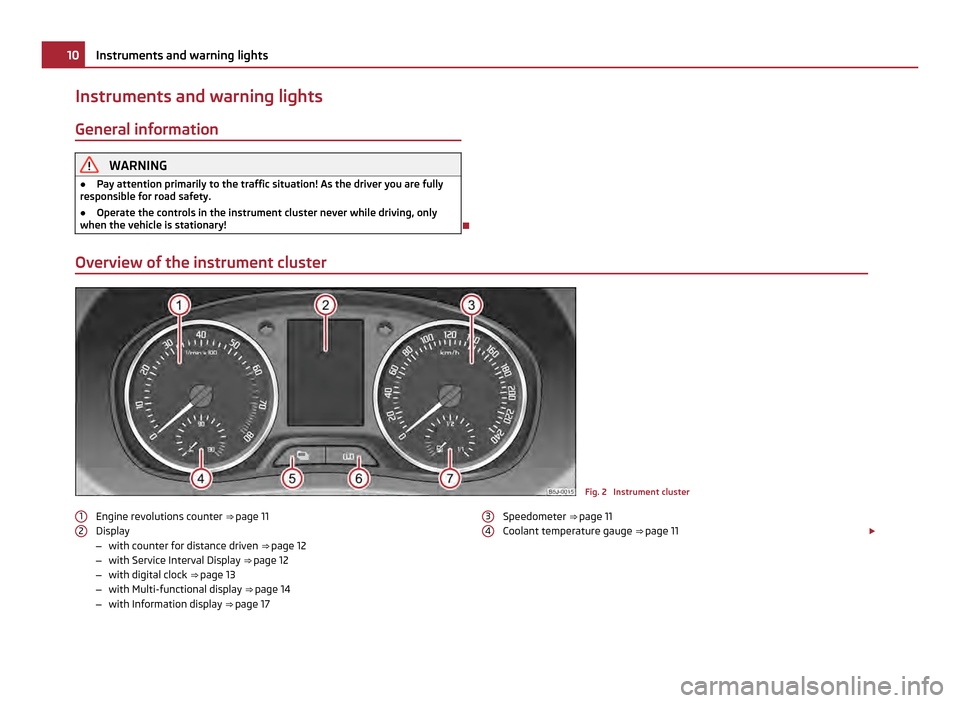
Overview of the instrument cluster Fig. 2 Instrument cluster
Engine revolutions counter ⇒ page 11
Display
– with counter for distance driven ⇒ page 12
– with Service Interval Display ⇒ page 12
– with digital clock ⇒ page 13
– with Multi-functional display ⇒ page 14
– with Information display ⇒ page 17
1 2 Speedometer ⇒
page 11
Coolant temperature gauge ⇒ page 11 £
3 410
Instruments and warning lights
Page 13 of 212
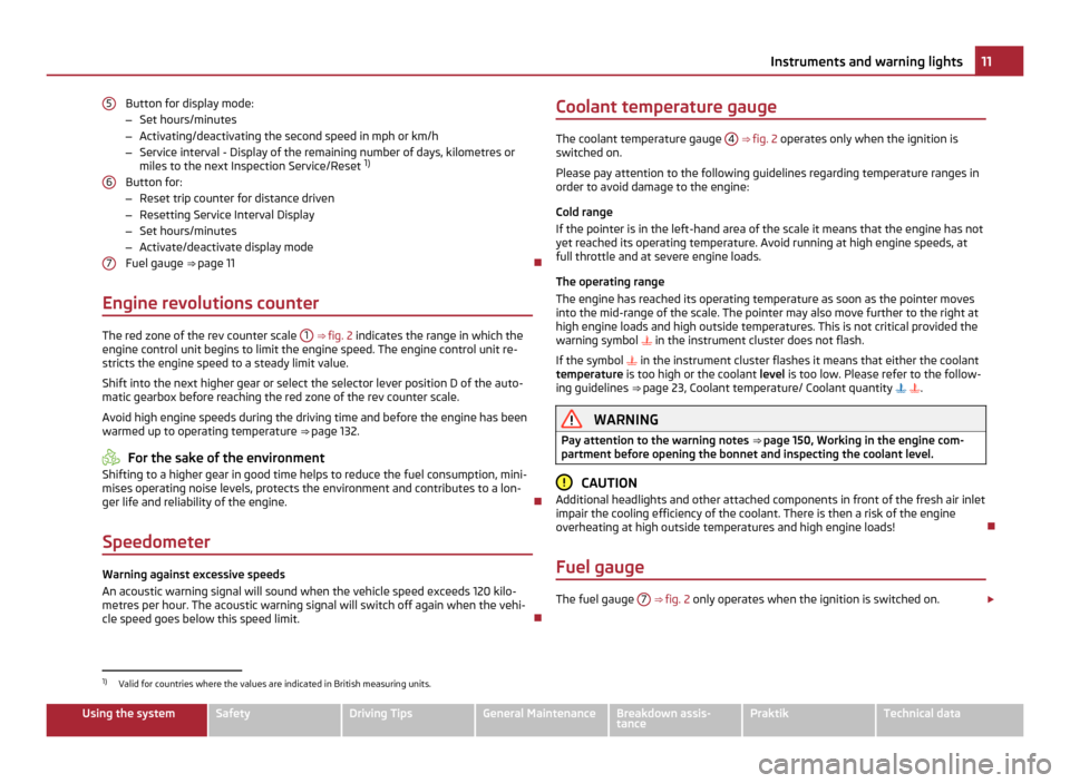
Button for display mode:
–
Set hours/minutes
– Activating/deactivating the second speed in mph or km/h
– Service interval - Display of the remaining number of days, kilometres or
miles to the next Inspection Service/Reset 1)
Button for:
– Reset trip counter for distance driven
– Resetting Service Interval Display
– Set hours/minutes
– Activate/deactivate display mode
Fuel gauge ⇒ page 11
Engine revolutions counter The red zone of the rev counter scale
1
⇒ fig. 2 indicates the range in which the
engine control unit begins to limit the engine speed. The engine control unit re-
stricts the engine speed to a steady limit value.
Shift into the next higher gear or select the selector lever position D of the auto-
matic gearbox before reaching the red zone of the rev counter scale.
Avoid high engine speeds during the driving time and before the engine has been
warmed up to operating temperature ⇒ page 132. For the sake of the environment
Shifting to a higher gear in good time helps to reduce the fuel consumption, mini-
mises operating noise levels, protects the environment and contributes to a lon-
ger life and reliability of the engine.
Speedometer Warning against excessive speeds
An acoustic warning signal will sound when the vehicle speed exceeds 120 kilo-
metres per hour. The acoustic warning signal will switch off again when the vehi-
cle speed goes below this speed limit.
5 6
7 Coolant temperature gauge
The coolant temperature gauge
4 ⇒ fig. 2
operates only when the ignition is
switched on.
Please pay attention to the following guidelines regarding temperature ranges in
order to avoid damage to the engine:
Cold range
If the pointer is in the left-hand area of the scale it means that the engine has not
yet reached its operating temperature. Avoid running at high engine speeds, at
full throttle and at severe engine loads.
The operating range
The engine has reached its operating temperature as soon as the pointer moves
into the mid-range of the scale. The pointer may also move further to the right at
high engine loads and high outside temperatures. This is not critical provided the
warning symbol in the instrument cluster does not flash.
If the symbol in the instrument cluster flashes it means that either the coolant
temperature is too high or the coolant level is too low. Please refer to the follow-
ing guidelines ⇒ page 23, Coolant temperature/ Coolant quantity . WARNING
Pay attention to the warning notes ⇒ page 150
, Working in the engine com-
partment before opening the bonnet and inspecting the coolant level. CAUTION
Additional headlights and other attached components in front of the fresh air inlet
impair the cooling efficiency of the coolant. There is then a risk of the engine
overheating at high outside temperatures and high engine loads!
Fuel gauge The fuel gauge
7
⇒
fig. 2 only operates when the ignition is switched on. £1)
Valid for countries where the values are indicated in British measuring units. 11
Instruments and warning lights Using the system Safety Driving Tips General Maintenance Breakdown assis-
tance Praktik Technical data
Page 22 of 212
Warning lights
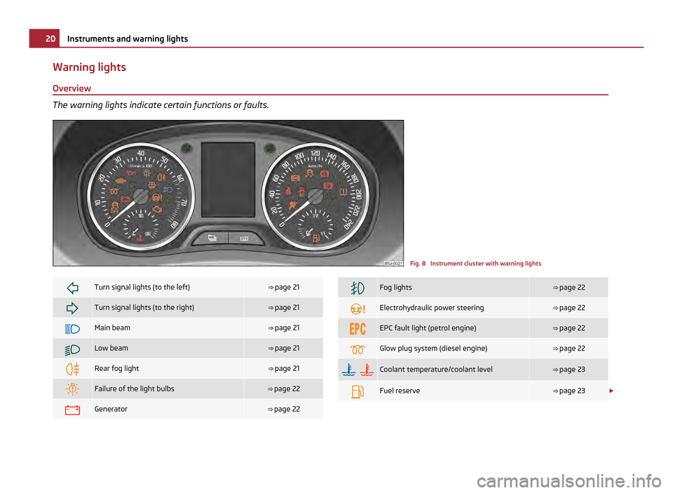
Overview The warning lights indicate certain functions or faults.
Fig. 8 Instrument cluster with warning lights
Turn signal lights (to the left) ⇒
page 21 Turn signal lights (to the right) ⇒
page 21 Main beam ⇒
page 21 Low beam ⇒
page 21 Rear fog light ⇒
page 21 Failure of the light bulbs ⇒
page 22 Generator ⇒
page 22 Fog lights ⇒
page 22 Electrohydraulic power steering ⇒
page 22 EPC fault light (petrol engine) ⇒
page 22 Glow plug system (diesel engine) ⇒
page 22
Coolant temperature/coolant level ⇒
page 23 Fuel reserve ⇒
page 23 £20
Instruments and warning lights
Page 25 of 212
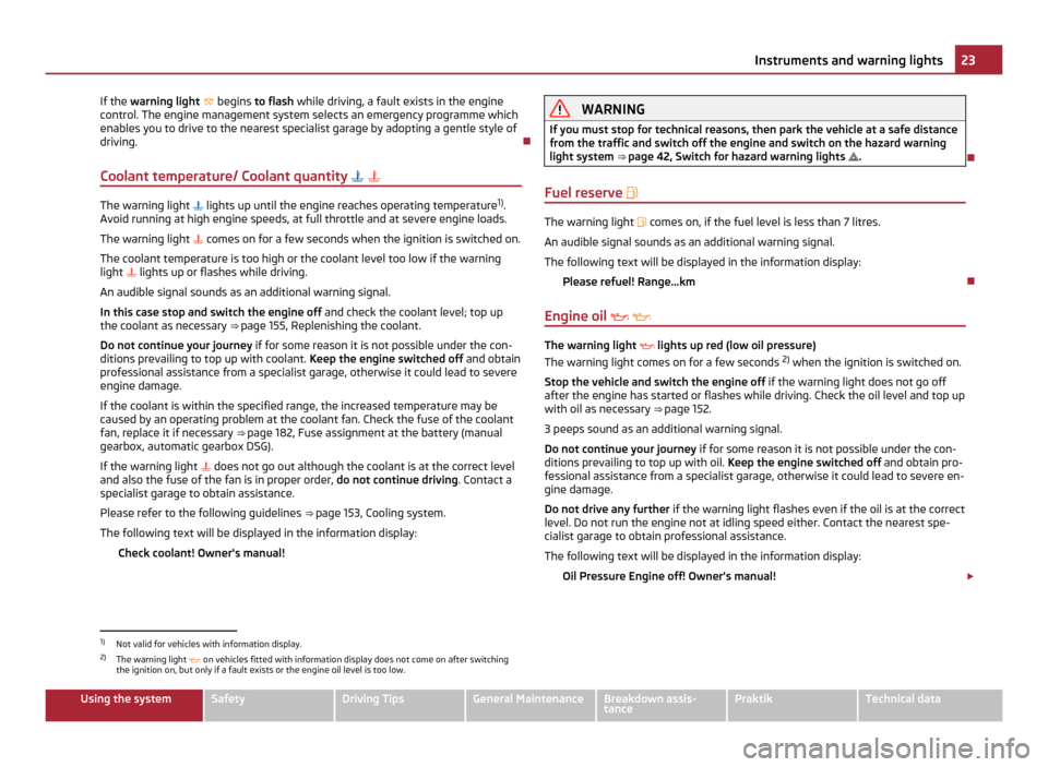
If the
warning light begins to flash while driving, a fault exists in the engine
control. The engine management system selects an emergency programme which
enables you to drive to the nearest specialist garage by adopting a gentle style of
driving.
Coolant temperature/ Coolant quantity The warning light
lights up until the engine reaches operating temperature 1)
.
Avoid running at high engine speeds, at full throttle and at severe engine loads.
The warning light comes on for a few seconds when the ignition is switched on.
The coolant temperature is too high or the coolant level too low if the warning
light lights up or flashes while driving.
An audible signal sounds as an additional warning signal.
In this case stop and switch the engine off and check the coolant level; top up
the coolant as necessary ⇒ page 155, Replenishing the coolant
.
Do not continue your journey if for some reason it is not possible under the con-
ditions prevailing to top up with coolant. Keep the engine switched off and obtain
professional assistance from a specialist garage, otherwise it could lead to severe
engine damage.
If the coolant is within the specified range, the increased temperature may be
caused by an operating problem at the coolant fan. Check the fuse of the coolant
fan, replace it if necessary ⇒ page 182, Fuse assignment at the battery (manual
gearbox, automatic gearbox DSG).
If the warning light does not go out although the coolant is at the correct level
and also the fuse of the fan is in proper order, do not continue driving. Contact a
specialist garage to obtain assistance.
Please refer to the following guidelines ⇒ page 153, Cooling system.
The following text will be displayed in the information display: Check coolant! Owner's manual! WARNING
If you must stop for technical reasons, then park the vehicle at a safe distance
from the traffic and switch off the engine and switch on the hazard warning
light system ⇒ page 42
, Switch for hazard warning lights .
Fuel reserve The warning light
comes on, if the fuel level is less than 7 litres.
An audible signal sounds as an additional warning signal.
The following text will be displayed in the information display: Please refuel! Range...km
Engine oil The warning light
lights up red (low oil pressure)
The warning light comes on for a few seconds 2)
when the ignition is switched on.
Stop the vehicle and switch the engine off if the warning light does not go off
after the engine has started or flashes while driving. Check the oil level and top up
with oil as necessary ⇒
page 152.
3 peeps sound as an additional warning signal.
Do not continue your journey if for some reason it is not possible under the con-
ditions prevailing to top up with oil. Keep the engine switched off and obtain pro-
fessional assistance from a specialist garage, otherwise it could lead to severe en-
gine damage.
Do not drive any further if the warning light flashes even if the oil is at the correct
level. Do not run the engine not at idling speed either. Contact the nearest spe-
cialist garage to obtain professional assistance.
The following text will be displayed in the information display:
Oil Pressure Engine off! Owner's manual! £1)
Not valid for vehicles with information display.
2) The warning light on vehicles fitted with information display does not come on after switching
the ignition on, but only if a fault exists or the engine oil level is too low. 23
Instruments and warning lights Using the system Safety Driving Tips General Maintenance Breakdown assis-
tance Praktik Technical data
Page 26 of 212
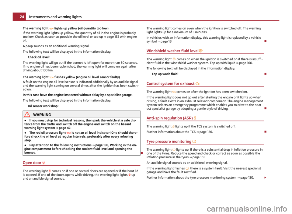
The warning light
lights up yellow (oil quantity too low)
If the warning light lights up yellow, the quantity of oil in the engine is probably
too low. Check as soon as possible the oil level or top up ⇒
page 152 with engine
oil.
A peep sounds as an additional warning signal.
The following text will be displayed in the information display: Check oil level!
The warning light will go out if the bonnet is left open for more than 30 seconds.
If no engine oil has been replenished, the warning light will come on again after
driving about 100 km.
The warning light flashes yellow (engine oil level sensor faulty)
A fault on the engine oil level sensor is indicated additionally by an audible signal
and the warning light coming on several times after the ignition has been switch-
ed on.
In this case have the engine inspected without delay by a specialist garage.
The following text will be displayed in the information display:
Oil sensor workshop! WARNING
● If you must stop for technical reasons, then park the vehicle at a safe dis-
tance from the traffic and switch off the engine and switch on the hazard
warning light system ⇒ page 42
.
● The red oil pressure light is not an oil level indicator! One should there-
fore check the oil level at regular intervals, preferably after every refueling
stop.
● Pay attention to the following instructions ⇒ page 150
, Working in the en-
gine compartment before checking the coolant fluid level and opening the
bonnet.
Open door The warning light
comes on if one or several doors are opened or if the boot lid
is opened. If one of the doors opens while driving, the warning light lights up
and an audible signal sounds. The warning light comes on even when the ignition is switched off. The warning
light lights up for a maximum of 5 minutes.
In vehicles with an information display, this warning light is replaced by a vehicle
symbol ⇒ page 18
Windshield washer fluid level The warning light
comes on when the ignition is switched on if there is insuffi-
cient fluid in the windshield washer system. Top up with liquid ⇒ page 160.
The following text will be displayed in the information display: Top up wash fluid!
Control system for exhaust The warning light
comes on after the ignition has been switched on.
If the warning light does not go out after starting the engine or it lights up when
driving, a fault exists in an exhaust relevant component. The engine management
system selects an emergency programme which enables you to drive to the near-
est specialist garage by adopting a gentle style of driving.
Anti-spin regulation (ASR) The warning light
lights up if the TCS system is switched off.
Further information about the TCS ⇒ page 126
.
Tyre pressure monitoring The warning light
lights up, if there is a substantial drop in inflation pressure in
one of the tyres. Reduce the speed and check or correct as soon as possible the
inflation pressure in the tyres ⇒
page 161.
An audible signal sounds as an additional warning signal.
If the warning light flashes , there is a system fault. Visit the nearest specialist
garage and have the fault rectified.
Further information about the tyre pressure monitoring system ⇒ page 130. £24
Instruments and warning lights
Page 71 of 212
Heating and air conditioning system
Introduction
Description and information The heating effect is dependent upon the coolant temperature, thus full heat out-
put only occurs when the engine has reached its operating temperature.
If the cooling system is switched on, the temperature and air humidity drops in
the vehicle. The well-being of the occupants of the car is enhanced as a result of
this particularly at high outside temperatures and a high air humidity. The system
prevents the windows misting up during the cold season of the year.
It is possible to briefly activate recirculated air mode in order to enhance the cool-
ing effect - air-conditioning system ⇒
page 74, Climatronic ⇒ page 77.
The air inlet in front of the windshield must be free of ice, snow or leaves in order
to ensure that the heating and cooling systems operate properly.
After switching on the cooling Condensation from the evaporator of the air condi-
tioning may drip down and form a puddle below the vehicle. This is quite normal
and not an indication of a leak! WARNING
● For your own safety and that of other road users, ensure that all the win-
dows are free of ice, snow and misting. Please familiarize yourself about how
to correctly operate the heating and ventilation systems, how to demist and
defrost the windows, as well as with the cooling mode.
● You should not leave recirculated air mode on over a longer period of time,
as
“stale” air may result in fatigue in the driver and occupants, divert your at-
tention and also cause the windows to mist up. The risk of having an accident
increases. Switch recirculated air mode off as soon as the windows begin
misting up. Note
● The used air streams out through the air removal openings in the luggage
compartment.
● We recommend that you do not smoke in the vehicle when the recirculating air
mode is operating since the smoke which is drawn at the evaporator from the in-
terior of the vehicle forms deposits in the evaporator of the air conditioning sys- tem. This produces a permanent odour when the air conditioning system is oper-
ating which can only be eliminated through considerable effort and expense (re-
placement of compressor).
● Please refer to the information regarding the recirculated air mode for heating
⇒
page 71 and/or for air-conditioning system ⇒ page 74 or Climatronic
⇒ page 77.
● To ensure that the heating and air conditioning systems work properly, do not
block up the air outlet vents with any objects.
Using the air conditioning system economically The compressor on the air conditioning system uses power from the engine when
in cooling mode which will effect the fuel consumption.
It recommended to open the windows or the doors of a vehicle for which the inte-
rior has been strongly heated through the effect of direct sunlight in order to al-
low the heated air to escape.
The cooling system should not be switched on while travelling when the window
is open.
The desired interior temperature can also be achieved without switching in the
cooling system just by switching to fresh air mode. For the sake of the environment
When you economize on fuel, you also reduce pollutant emissions.
Operational problems If the cooling system does not operate at outside temperatures higher than +5 °C,
there is a problem in the system. The reasons for this may be:
●
The fuse on the air conditioning system has blown. Check the fuse, replace it if
necessary ⇒ page 179.
● The cooling system has switched off automatically for a short time because
the coolant temperature of the engine is too hot ⇒ page 11.
If you are not able to rectify the operational problem yourself, or if the cooling ca-
pacity decreases, switch the cooling system off. Contact a specialist garage. 69
Heating and air conditioning system Using the system Safety Driving Tips General Maintenance Breakdown assis-
tance Praktik Technical data
Page 77 of 212
The recirculated air mode is switched off automatically if the air distribution con-
trol
C is in position ⇒
fig. 75. You can also switch recirculated air mode on
again from this setting by repeatedly pressing pushbutton .
WARNING
You should not leave recirculated air mode on over a longer period of time, as
“stale
” air may result in fatigue in the driver and occupants, divert your atten-
tion and also cause the windows to mist up. The risk of having an accident in-
creases. Switch recirculated air mode off as soon as the windows begin mist-
ing up.
Climatronic (automatic air conditioning) Description The Climatronic system is an automatic heating, fresh air and cool-
ing system which provides optimal comfort for the occupants of the
car.
The Climatronic maintains a constant temperature fully automatically, once it has
been set. This is achieved by automatically varying the temperature of the out-
flowing air, the blower stages and the air distribution. The system also takes into
account sunlight which eliminates the need to alter the settings manually. The
automatic mode ⇒ page 76 ensures maximum well-being of the occupants at all
times of the year.
Description of Climatronic system
The cooling operates only if the following conditions are met:
● engine running,
● outside temperature above approx. +2 °C,
● AC switched on.
The AC compressor is switched off at a high coolant temperature in order to en-
sure cooling of the engine at high loads. Recommended setting for all periods of the year:
●
Set the desired temperature, we recommend 22 °C (72 °F).
● Press the button AUTO ⇒ fig. 76
.
● Move the air outlet vents 3 and 4 so that the air flow is directed slightly up-
wards.
Switching over between degrees Celsius and degrees Fahrenheit
Press and hold the buttons AUTO and
AC ⇒ fig. 76
at the same time. The informa-
tion in the desired temperature measuring unit appears in the display. Note
● We recommend that you have Climatronic cleaned by a specialist garage once
every year.
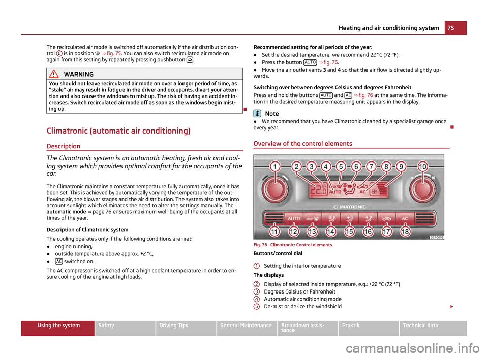
Overview of the control elements Fig. 76 Climatronic: Control elements
Buttons/control dial
Setting the interior temperature
The displays Display of selected inside temperature, e.g.: +22
°C (72 °F)
Degrees Celsius or Fahrenheit
Automatic air conditioning mode
De-mist or de-ice the windshield £
1 2
3
4
5 75
Heating and air conditioning system Using the system Safety Driving Tips General Maintenance Breakdown assis-
tance Praktik Technical data
Page 82 of 212
For the sake of the environment
Never warm up the engine when the vehicle is standing. Drive off right away.
When driving the engine reaches its operating temperature more rapidly and the
pollutant emissions are lower.
Petrol engines These engines are fitted with a starter system which selects the correct fuel-air
mixture for every external air temperature.
●
Do not operate accelerator before and when starting engine.
● Interrupt the attempt at starting after 10 seconds if the engine does not start
right away and wait for about 30 seconds before repeating the attempt.
● It is possible that the fuse on the electrical fuel pump is defect if the engine
still does not start. Check the fuse and replace it if necessary ⇒ page 179.
● If the engine does not start, contact the nearest specialist garage to obtain
professional assistance.
It may be necessary, if the engine is very hot, to slightly depress the accelerator
after the engine has started.
Diesel engines Glow plug system
Diesel engines are equipped with a glow plug system, the pre-glow period being
controlled automatically in line with the coolant temperature and outside temper-
ature.
The pre-glow indicator light comes on after the ignition has been switched on.
You should not switch on any major electrical components during the heating
period otherwise the vehicle battery will be drained unnecessarily.
● You should start the engine immediately after the glow plug warning light
has gone out.
● The glow plug warning light will come on for about one second if the engine is
at a normal operating temperature or if the outside temperature is above +5 °C.
This means that you can start the engine right away.
● Interrupt the attempt at starting after 10 seconds if the engine does not start
right away and wait for about 30 seconds before repeating the attempt. ●
It is possible that the fuse on the diesel pre-glow system is defect if the en-
gine still does not start. Check the fuse and replace it if necessary ⇒ page 179.
● Contact the nearest specialist garage to obtain professional assistance.
Starting the engine after fuel tank has run dry
It may take longer than normal to start the engine after refuelling if the fuel tank
has run completely dry - up to one minute. This is because the fuel system must
first of all be filled while the attempting to start the engine.
Switching off the engine –
The engine can be switched off by turning the ignition key into position 1 ⇒
fig. 78 . WARNING
● Never switch off the engine before the vehicle is stationary - risk of acci-
dent!
● The brake booster only operates when the engine is running. Greater
physical effort for braking is required when engine is switched off. Because if
you do not stop as normal, this can cause an accident and severe injuries. CAUTION
you should not switch the engine off right away at the end of your journey after
the engine has been operated for a lengthy period at high loads but should be al-
lowed it to run at idling speed for about 2
minutes. This prevents any accumula-
tion of heat when the engine is switched off. Note
● The radiator fan may continue running for a further 10 minutes or so after the
engine and the ignition have been switched off. The coolant fan may, however, al-
so switch on again after some time if the coolant temperature rises because of an
accumulation of heat in the engine or if the engine is warm and the engine com-
partment is additionally heated by strong sunlight.
● This is why particular care is required when carrying out any work in the en-
gine compartment ⇒
page 150, Working in the engine compartment. 80
Starting-off and Driving
Page 142 of 212
Driving Tips
–
Do not, as far as possible, drive with your vehicle unladen and the trailer laden.
– Do not make full use of the legal maximum speeds. This applies in particular to
downhill sections.
– Apply the brakes in good time.
– Keep a check on the coolant temperature gauge if the outside temperature is
high.
Distribution of weight
The distribution of the weight is very poor if your vehicle is unladen and the trailer
is laden. Maintain a particularly low speed if you cannot avoid driving with this
combination.
Driving speed
Do not drive faster than 80
km/h for safety reasons. This also applies for countries
in which higher speeds are allowed.
The fact that the driving stability of the vehicle + trailer combination reduces with
increasing speed means that the legally allowed speed should not be used when
there are unfavourable road, weather or wind conditions, particularly near acci-
dent black spots.
You must always reduce your speed immediately as soon as you detect even just
the slightest swaying of the trailer. On no account attempt to stop the trailer
from “swaying” by accelerating.
Apply the brakes in good time! If the trailer is fitted with a trailer brake, apply the
brakes gently at first and then brake firmly. This will avoid brake jolts resulting
from the trailer wheels locking. Shift down gears in good time before negotiating
a downhill section to allow the engine to also act as a brake.
Engine overheating
Please keep a check on the coolant temperature gauge if you have to negotiate a
lengthy slope in a low gear at a high engine speed when the outside temperature
is very high ⇒ page 11.
If the needle of the coolant temperature gauge moves into the right-hand area or
even the red area of the scale, reduce your speed immediately. Stop and switch
off the engine if the warning light in the instrument cluster begins flashing.
Wait a few minutes and check the level of coolant in the coolant expansion bottle
⇒ page 154, Inspecting the coolant level. Please refer to the following guidelines
⇒
page 23, Coolant temperature/ Coolant
quantity .
The coolant temperature can be reduced by switching on the heating.
Any increase in the cooling effect of the coolant fan through shifting down a gear
and increasing the engine speed is not possible since the fan speed is independ-
ent of the engine speed. One should also not drop a gear for this reason when
towing a trailer as long as the engine can manage the slope without any drop in
speed. 140
Towing a trailer